Sign In
Upload
Download
Table of Contents
Contents
Add to my manuals
Delete from my manuals
Share
URL of this page:
HTML Link:
Bookmark this page
Add
Manual will be automatically added to "My Manuals"
Print this page
×
Bookmark added
×
Added to my manuals
Manuals
Brands
Beckhoff Manuals
Touch terminals
KL3311
Documentation
Beckhoff KL3311 Documentation
Single, dual- and four-channel analog imput terminals for thermocouples
Hide thumbs
1
2
3
4
5
6
7
8
9
10
11
12
13
14
15
16
17
18
19
20
21
22
23
24
25
26
27
28
29
30
31
32
33
34
35
36
37
38
39
40
41
42
43
44
45
46
47
48
49
50
51
page
of
51
Go
/
51
Contents
Table of Contents
Bookmarks
Table of Contents
Table of Contents
1 Foreword
Notes on the Documentation
Safety Instructions
Documentation Issue Status
Beckhoff Identification Code (BIC)
Fig. 1 BIC as Data Matrix Code (DMC, Code Scheme ECC200)
2 Product Overview
Introduction
Fig. 2 KL3311, KL3312 and KL3314
Technical Data
Basic Function Principles
Fig. 3 Principle of the Thermocouple
Fig. 4 Data Flow
3 Mounting and Wiring
Instructions for ESD Protection
Installation on Mounting Rails
Fig. 5 Spring Contacts of the Beckhoff I/O Components
Fig. 6 Attaching on Mounting Rail
Fig. 7 Disassembling of Terminal
Fig. 8 Power Contact on Left Side
Installation Instructions for Enhanced Mechanical Load Capacity
Connection
Connection System
Fig. 9 Standard Wiring
Fig. 10 Pluggable Wiring
Fig. 11 High Density Terminals
Wiring
Fig. 12 Connecting a Cable on a Terminal Point
Shielding
KL3311 - Connection and LED Description
Fig. 13 KL3311 - Connection and Leds
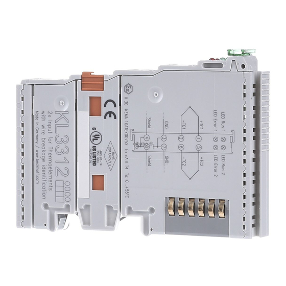
KL3312, KL3302 - Connection and LED Description
Fig. 14 KL3312, KL3302 - Connection and Leds
KL3314 - Connection and LED Description
Fig. 15 KL3314 - Connection and Leds
Connection of Ground, Shield und Earthing
Fig. 16 KL3312 - Connection of Ground, Shield und Earthing (Left: Earthed Thermocouple, Right: Non- Earthed Thermocouple)
ATEX - Special Conditions (Standard Temperature Range)
ATEX Documentation
4 KS2000 Configuration Software
KS2000 - Introduction
Fig. 17 KS2000 Configuration Software
Sample Program for KL Register Communication Via Ethercat on KL3314 Exemplary
Fig. 18: Settings of KL3314 Via Visualisation of Twincat 3
Fig. 19 Opening the *. Tnzip Archive
Fig. 20 Search of the Existing HW Configuration for the Ethercat Configuration of the Example
5 Access from the User Program
Kl331X, KL3302 - Terminal Configuration
Fig. 21 Mapping in the Lightbus Coupler - Example for KL3312, KL3302
Fig. 22 Mapping in the Profibus Coupler - Example for KL3312, KL3302
Mapping in the Bus Coupler
Fig. 23 Mapping in the Interbus Coupler - Example for KL3312, KL3302
KL3311 - Default Mapping
KL3312 (KL3302) - Default Mapping
KL3314 - Default Mapping
Register Overview
Register Description
Control and Status Byte
Register Communication
Fig. 24 Register Mode Control Byte
Examples of Register Communication
Example 1: Reading the Firmware Version from Register 9
Example 2: Writing to an User Register
6 Appendix
Support and Service
Table of Figures
Advertisement
Quick Links
1
Technical Data
2
Fig. 15 Kl3314 - Connection and Leds
Download this manual
Documentation
KL3311, KL3312, KL3314 and KL3302
Single, Dual- and Four-Channel Analog Imput Terminals for
Thermocouples
Version:
Date:
4.2
2019-10-08
Table of
Contents
Previous
Page
Next
Page
1
2
3
4
5
Advertisement
Chapters
Table of Contents
3
Table of Figures
51
Table of Contents
Need help?
Do you have a question about the KL3311 and is the answer not in the manual?
Ask a question
Questions and answers
Related Manuals for Beckhoff KL3311
Touch terminals Beckhoff KL3356 Documentation
Accurate 1 channel terminal for resistance bridges (55 pages)
Touch terminals Beckhoff KL3312 Documentation
Single, dual- and four-channel analog imput terminals for thermocouples (51 pages)
Touch terminals Beckhoff KL3314 Documentation
Single, dual- and four-channel analog imput terminals for thermocouples (51 pages)
Touch terminals Beckhoff KL304 Series Documentation
Single-, dual- and four-channel analog input terminals, measuring range: 0...20 ma and 4...20 ma, single ended (46 pages)
Touch terminals beckhoff KL3444 Documentation
Four and eight channel analog input terminals (58 pages)
Touch terminals Beckhoff KL344 Series Documentation
Four and eight channel analog input terminals (63 pages)
Touch terminals Beckhoff KL3214 Documentation
Four-channel hd input terminal for 3-wire connection ofresistance sensors. (44 pages)
Touch terminals Beckhoff KL31 2 Series Documentation
Two channel accurate analog terminals (56 pages)
Touch terminals Beckhoff KL3222 Documentation
2 channel accurate input terminals for pt100 (rtd) (43 pages)
Touch terminals Beckhoff KL3202 Documentation
Analog input terminals for pt100 (rtd) or ntc10k (54 pages)
Touch terminals Beckhoff KL3208 Manual
Eight channel input terminals for pt1000, ni1000, ntc (56 pages)
Touch terminals Beckhoff KL3228 Manual
Eight channel input terminals for pt1000, ni1000, ntc (56 pages)
Touch terminals Beckhoff KL3132 Manual
Two channel accurate analog terminals (63 pages)
Touch terminals Beckhoff KL3162 Manual
Two channel accurate analog terminals (63 pages)
Touch terminals Beckhoff KL3172 Manual
Two channel accurate analog terminals (63 pages)
Touch terminals Beckhoff KL3182 Manual
Two channel accurate analog terminals (63 pages)
This manual is also suitable for:
Kl3312
Kl3314
Kl3302
Table of Contents
Print
Rename the bookmark
Delete bookmark?
Delete from my manuals?
Login
Sign In
OR
Sign in with Facebook
Sign in with Google
Upload manual
Upload from disk
Upload from URL


Need help?
Do you have a question about the KL3311 and is the answer not in the manual?
Questions and answers