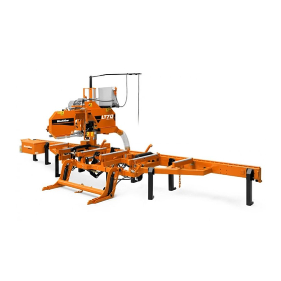
Summary of Contents for Wood-mizer LS LT60
- Page 1 Laser Sight Safety, Operation, Maintenance & Parts Manual LS LT60/70 rev. A.00 - E.00 Safety is our #1 concern! Read and understand all safety information and instructions before oper- ating, setting up or maintaining this machine. May 2002 Form #1081...
- Page 2 Printed in the United States of America, all rights reserved. No part of this man- ual may be reproduced in any form by any photographic, electronic, mechanical or other means or used in any information storage and retrieval system without written permission from Wood-Mizer 8180 West 10th Street Indianapolis, Indiana 46214...
-
Page 3: Table Of Contents
Table of Contents Section-Page SECTION 1 LASER INSTALLATION Laser Installation ..................1-1 Switch Installation ..................1-4 SECTION 2 OPERATION & ALIGNMENT Laser Operation ..................2-1 Laser Alignment ..................2-2 SECTION 3 REPLACEMENT PARTS Laser Assembly ..................3-1 Rev. E.00+ Laser Assembly ..................3-3 Rev. A.00 - D.01 INDEX Table of Contents 60LS02doc032619... -
Page 4: Laser Installation
Laser Installation Laser Installation SECTION 1 LASER INSTALLATION Before installing the laser option, be aware that the laser beam can not be seen in direct sunlight. The laser option is best for indoor cutting applications. Laser Installation 1. Locate the four square mounting holes on the saw head near the bottom of the drive-side blade housing. - Page 5 Laser Installation Laser Installation 2. Remove the drive belt guard. 3. Route the cable from the laser assembly as shown: See Figure 1-2. Route the laser cable under the saw head along the brace plate and secure the cable with the three provided wire clamps. Bolt the wire clamps to the brace plate with the three 1/4-20 x 1/2”...
- Page 6 Laser Installation Laser Installation Wire #26 600029-2 Wire #25 Wire Tie (2) Up/Down Motor Laser Cable Wire Harness Wire Clamp (3) FIG. 1-2 REV. A.00 - D.01 60LS02doc032619 Laser Installation...
-
Page 7: Switch Installation
Laser Installation Switch Installation Switch Installation 1. Unbolt the front panel from the control box. Use the hole in the front panel as a template to cut out a hole in the decal for the laser option switch. NOTE: The cut hole will be slightly smaller than indicated by the dotted line on the decal. - Page 8 Laser Installation Switch Installation 2. Install the toggle switch, nylon washer, and rubber boot to the front panel as shown. 3. DC Only: Connect the quick connect terminal on the existing laser option wire (labeled #25) to the bottom tab on the toggle switch. AC Only: Connect the quick connect terminals on the provided capacitor assembly to the bottom tab on the toggle switch and the existing laser option wire (labeled #25).
-
Page 9: Operation & Alignment
Operation & Alignment Laser Operation SECTION 2 OPERATION & ALIGNMENT Laser Operation When properly installed, the laser option will guide you in making cuts. To turn on the laser, raise the laser toggle switchlaser toggle switch to the ON position. To turn off the laser, lower the laser toggle switch to the OFF°... -
Page 10: Laser Alignment
Operation & Alignment Laser Alignment Laser Alignment 1. Stationary sawmills should be setup on firm, level ground before proceeding with align- ment. Shim the feet so the weight of the sawmill is evenly supported. Portable sawmills should also be setup on firm, level ground: LT60HD: Adjust the two middle outriggers on the main frame tube down just enough to lift weight from the trailer tire. - Page 11 Operation & Alignment Laser Alignment Mounting Bolts (4) 600475-3 FIG. 2-1 REV. E.00+ Mounting Bolts (4) 600029-3 FIG. 2-1 REV. A.00 - D.01 See Figure 2-2. If the laser beam is adjusted too low, it will show against the side of the cant.
- Page 12 Operation & Alignment Laser Alignment secure the bottom half of the papers to the cant. Use tack to secure in place Align fold of paper to outside edge of cant FIG. 2-2 60LS02doc032619 Operation & Alignment...
- Page 13 Operation & Alignment Laser Alignment See Figure 2-3. To adjust the laser horizontally, loosen the laser pivot screws. Pivot the laser diode side to side, or up and down, as necessary. Retighten the pivot screws to secure the diode in place. Pivot Screws Laser Diode 600475-4...
-
Page 14: Replacement Parts
600474 DESCRIPTION ( Indicates Parts Available In Assemblies Only) PART # QTY. LASER KIT, COMPLETE FOR LT60/70 LS LT60/70 Laser Assembly, 20 mW 638nm 90 Deg RED Line 073701 Mount Weldment, LT70 Laser 073863 Bolt, 5/16-18 x 1” Carriage Head... - Page 15 Replacement Parts Laser Assembly Bolt, 10-24 x 3/4” Unslotted Hex Head F05004-167 Nut, 10-24 Hex Nylon Lock F05010-160 Bag Assembly, LT60/LT70 Laser Parts 024195 Clamp, 1/4" Wire 9/32” Mounting Hole 025671 Tie Wrap, 1/4” x 6” F05089-1 Switch, Toggle P03027 Washer, 1/2”...
- Page 16 Rev. A.00 - D.01 600030B DESCRIPTION ( Indicates Parts Available In Assemblies Only) PART # QTY. LASER KIT, COMPLETE FOR LT60/70 LS LT60/70 Bracket Assembly, LT60/LT70 Laser 017833 Mount Weldment, LT60/LT70 Laser 034863 Bolt, 5/16-18 x 1” Carriage Head F05006-9 Washer, 5/16”...
- Page 17 Replacement Parts Laser Assembly Bracket, Laser Mount (Plastic) 045250 Power Supply, Laser w/Connector 050368 Tie Wrap, 1/4” x 6” F05089-1 Instruction Sheet, Laser Replacement 050500-1069 Screw, #8-32 X 5/8” Socket Button Head Stainless Steel F05004-98 Nut, #8-32 Self Locking F05010-41 Bag Assembly, LT60/LT70 Laser Parts 024195 Clamp, 1/4"...
- Page 18 INDEX alignment installation switch operation replacement parts 60LS02doc032619 Index...


Need help?
Do you have a question about the LS LT60 and is the answer not in the manual?
Questions and answers