Nibe ECS 40 Installer Manual
Extra climate system for nibe f1145, f1245, f1345, f370, f470, f750, vvm500
Hide thumbs
Also See for ECS 40:
- Installer manual (144 pages) ,
- Manual (40 pages) ,
- Installer manual (36 pages)
Advertisement
Available languages
Available languages
Quick Links
ECS 40/ECS 41
Installatörshandbok Extra Klimatsystem
SE
för NIBE F1145, F1245, F1345, F370, F470, F750,
VVM500
Installer manual Extra climate system
GB
for NIBE F1145, F1245, F1345, F370, F470, F750,
VVM500
Installateurhandbuch Extra mischgruppe
DE
für NIBE F1145, F1245, F1345, F370, F470, F750,
VVM500
Asentajan käsikirja Lisälämmitysjärjestelmä
FI
NIBE F1145, F1245, F1345, F370, F470, F750,
VVM500
IHB 1218-3
031431
Advertisement

Related Manuals for Nibe ECS 40


Summary of Contents for Nibe ECS 40
- Page 1 ECS 40/ECS 41 Installatörshandbok Extra Klimatsystem för NIBE F1145, F1245, F1345, F370, F470, F750, VVM500 Installer manual Extra climate system for NIBE F1145, F1245, F1345, F370, F470, F750, VVM500 Installateurhandbuch Extra mischgruppe für NIBE F1145, F1245, F1345, F370, F470, F750, VVM500 Asentajan käsikirja Lisälämmitysjärjestelmä...
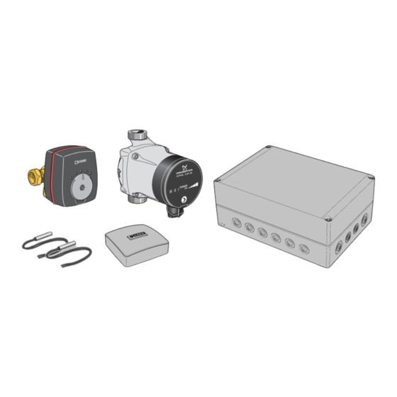
- Page 3 2 st Utbytespackning 2 st Temperaturgivare AA5-S2 DIP-switch 1 st Rumsgivare AA5-F1 Finsäkring, T4AH250V 1 st Rör med rak koppling* Beteckningar i komponentplacering enligt standard IEC * Detta används endast vid inkoppling till NIBE F370 eller 81346-1 och 81346-2. F470.
- Page 4 Röranslutning Retur Allmänt Vid anslutning av extra klimatsystem måste de kopplas så att de har lägre arbetstemperatur är klimatsystem 1. Värmepump/ Framledning innemodul Cirkulationspump och shuntventil Den extra cirkulationspumpen (GP20) placeras i det extra klimatsystemet enligt principschema. F1145/F1245/F1345/F750/VVM500 Shuntventilen (QN25) placeras på framledningen efter värmepumpen/innemodulen, före första radiator på...
- Page 5 Pump- och tryckfallsdiagram, ECS 40 Tillgängligt tryck Flöde Flöde 1000 1200 1400 1600 Pump- och tryckfallsdiagram, ECS 41 Tillgängligt tryck Max flöde: 1700 l/h Max flöde: 1700 l/h Flöde Flöde 1000 1200 1400 1600 1800 2000...
- Page 6 QM57 QN10 Växelventil, värme/varmvatten RM10 - Backventil RM13 EB101 Värmepumpsystem (slav) EB101 Värmepump EP21 Klimatsystem 2 (ECS 40/ECS 41) Tillbehörskort Framledningsgivare, extra klimatsystem Returledningsgivare, extra klimatsystem GP20 Cirkulationspump, extra klimatsystem QN25 Shuntventil EP22 Klimatsystem 3 (ECS 40/ECS 41) EP23 Klimatsystem 4 (ECS 40/ECS 41) Övrigt...
- Page 7 Principschema F1145 med ECS 40/ECS 41 och upp till tre extra klimatsystem -EP23 -AA5 -BT2 -GP20 -BT3 -QN25 -EP22 -AA5 -BT2 -GP20 -BT3 -QN25 -EP21 -AA5 -BT2 -GP20 -BT3 -QN25 -EB100-BT1 -QM12 -FL2 -CM2 -CM1 -QM42 -XL15 -QM31 -FL3 -EB100...
- Page 8 Principschema F1345 med ECS 40/ECS 41 och upp till tre extra klimatsystem -EP23 -AA5 -BT2 -GP20 -BT3 -QN25 -EP22 -AA5 -BT2 -GP20 -BT3 -QN25 -EP21 -AA5 -BT2 -GP20 -BT3 -EB1 -QN25 -FL10 -CM5 -EB1 -CP20 -EB100-BT25 -GP10 -GP18 -QM42 -EB100-BT71...
- Page 9 Principschema F750 med ECS 40/ECS 41 och upp till tre extra klimatsystem -EP23 -AA5 -BT2 -GP20 -BT3 -QN25 -EP22 -AA5 -BT2 -GP20 -EB100 -BT3 -QN25 -EB100 -EP21 -AA5 -BT2 -GP20 -BT3 -QN25 Principschema VVM500 med ECS 40/ECS 41 och upp till tre extra klimatsystem...
- Page 10 1 2 3 4 Elektrisk installation och ledningsdragning skall utföras enligt gällande bestämmelser. Vämepumpen/innemodulen ska vara spännings- lös vid installation av ECS 40/ECS 41. Elschema finns i slutet av denna installatörshandbok. Anslutning av matning Anslut spänningsmatningen till plint X1 enligt bild.
- Page 11 Anslutning av cirkulationspump (GP20) Anslut cirkulationspumpen (GP20) till AA5-X9:8 (230 V), AA5-X9:7 (N) och X1:3 (PE). -X10 Anslutning av givare och extern justering Använd kabeltyp LiYY, EKKX eller likvärdig. Framledningsgivare, extra klimatsystem (BT2) Anslutning av shuntmotor (QN25) Anslut framledningsgivaren till AA5-X2:23-24. Anslut shuntmotorn (QN25) till AA5-X9:6 (230 V, öppna), AA5-X9:5 (N) och AA5-X9:4 (230 V, stäng).
- Page 12 Programinställningar TÄNK PÅ! Se även Installatörshandboken för respektive Programinställningen av ECS 40/ECS 41 kan göras via värmepump/innemodul. startguiden eller direkt i menysystemet. Startguiden Tekniska data Startguiden visas vid första uppstart efter värmepumps- /innemodulsinstallationen, men finns även i meny 5.7. Menysystemet Manöverspänning...
-
Page 14: Table Of Contents
DIP switch Replacement gasket AA5-F1 Fine wire fuse, T4AH250V Temperature sensor Room sensor Designations in component locations according to Pipe with straight coupling* standard IEC 81346-1 and 81346-2. * This is only used when connecting to NIBE F370 or F470. - Page 15 Pipe connections Return General When connecting extra climate systems, they must be connected so that they have a lower working temperature Heat pump Flow pipe than the climate system 1. Circulation pump and mixing valve The extra circulation pump (GP20) is positioned in the extra climate system according to the outline diagram.
- Page 16 Pump and pressure drop diagrams, ECS 40 Available pressure Flow Flöde 1000 1200 1400 1600 Pump and pressure drop diagrams, ECS 41 Available pressure Max flow: 1700 l/h Max flöde: 1700 l/h Flow Flöde 1000 1200 1400 1600 1800 2000...
- Page 17 Non-return valve RM13 EB101 Heat pump system (slave) EB101 Heat pump EP21 Climate system 2 (ECS 40/ECS 41) Accessory card Flow temperature sensor, extra climate system Return line sensor, extra climate system GP20 Circulation pump, extra climate system QN25 Shunt valve...
- Page 18 Outline diagram F1145 with ECS 40/ECS 41 and up to three extra climate systems -EP23 -AA5 -BT2 -GP20 -BT3 -QN25 -EP22 -AA5 -BT2 -GP20 -BT3 -QN25 -EP21 -AA5 -BT2 -GP20 -BT3 -QN25 -EB100-BT1 -QM12 -FL2 -CM2 -CM1 -QM42 -XL15 -QM31...
- Page 19 Outline diagram F1345 with ECS 40/ECS 41 and up to three extra climate systems -EP23 -AA5 -BT2 -GP20 -BT3 -QN25 -EP22 -AA5 -BT2 -GP20 -BT3 -QN25 -EP21 -AA5 -BT2 -GP20 -BT3 -EB1 -QN25 -FL10 -CM5 -EB1 -CP20 -EB100-BT25 -GP10 -GP18...
- Page 20 Outline diagram F750 with ECS 40/ECS 41 and up to three extra climate systems -EP23 -AA5 -BT2 -GP20 -BT3 -QN25 -EP22 -AA5 -BT2 -GP20 -EB100 -BT3 -QN25 -EB100 -EP21 -AA5 -BT2 -GP20 -BT3 -QN25 Outline diagram VVM500 with ECS 40/ECS 41 and up to three extra climate systems...
- Page 21 Electrical installation and wiring must be carried out in accordance with the stipulations in force. The heat pump must not be powered when in- stalling ECS 40/ECS 41. The electrical circuit diagram is at the end of this Installer handbook.
-
Page 22: Aa5-S2
Connection of the circulation pump (GP20) Connect the circulation pump (GP20) to AA5-X9:8 (230 V), AA5-X9:7 (N) and X1:3 (PE). -X10 Connection of sensors and external adjust- ment Use cable type LiYY, EKKX or similar. Connection of the mixing valve motor (QN25) Flow temperature sensor, extra climate system Connect the mixing valve motor (QN25) to AA5-X9:6 (BT2) - Page 23 EP2#-AA5-K4: Activating the circulation pump (GP20). Program settings Caution Program setting of ECS 40/ECS 41 can be performed via Also see the Installer manual for relevant heat the start guide or directly in the menu system. pump/indoor module. Start guide...
-
Page 25: Aa5-X4
2 St. Dichtung AA5-F1 Feinsicherung, T4AH250V 2 St. Fühler 1 St. Raumtemperaturfühler Bezeichnungen der Komponentenpositionen gemäß Standard IEC 81346-1 und 81346-2. 1 St. Rohr mit gerader Kupplung* * Dies wird nur bei einem Anschluss an NIBE F370 oder F470 verwendet. - Page 26 Rohranschluss/Durchflussmes- Rücklauf Allgemeines Wärmepumpe Vorlauf Bei Anschluss zusätzlicher Klimatisierungssysteme müssen diese so eingebunden werden, dass sie eine niedrigere Betriebstemperatur als Klimatisierungssystem 1 besitzen. Umwälzpumpe und Mischventil Die zusätzliche Umwälzpumpe (GP20) wird im zusätzli- chen Heiz- und Kühlkreis platziert (siehe Prinzipskizze). Fühler F1145/F1245/F1345/F750/VVM500 Der Vorlauffühler (BT2) wird am Rohr zwischen Umwälz-...
- Page 27 Pumpenkennliniendiagramm, ECS 40 Verfügbarer Druck Fluss Flöde 1000 1200 1400 1600 Pumpenkennliniendiagramm, ECS 41 Verfügbarer Druck Max. Durchfluss: 1700 l/h Max flöde: 1700 l/h Fluss Flöde 1000 1200 1400 1600 1800 2000...
- Page 28 Umschaltventil, Heizung/Brauchwasser RM10 - Rückschlagventil RM13 EB101 Wärmepumpensystem (Slave) EB101 Wärmepumpe EP21 Klimatisierungssystem 2 (ECS 40/ECS 41) Zubehörplatine Vorlauffühler für zusätzlichen Heiz- und Kühlkreis Rücklauffühler für zusätzlichen Heiz- und Kühlkreis GP20 Umwälzpumpe für zusätzlichen Heiz- oder Kühlkreis QN25 Mischventil EP22...
- Page 29 Prinzipskizze F1145 mit ECS 40/ECS 41 und bis zu drei zusätzlichen Klimatisierungssystemen -EP23 -AA5 -BT2 -GP20 -BT3 -QN25 -EP22 -AA5 -BT2 -GP20 -BT3 -QN25 -EP21 -AA5 -BT2 -GP20 -BT3 -QN25 -EB100-BT1 -QM12 -FL2 -CM2 -CM1 -QM42 -XL15 -QM31 -FL3 -EB100...
- Page 30 Prinzipskizze F1345 mit ECS 40/ECS 41 und bis zu drei zusätzlichen Klimatisierungssystemen -EP23 -AA5 -BT2 -GP20 -BT3 -QN25 -EP22 -AA5 -BT2 -GP20 -BT3 -QN25 -EP21 -AA5 -BT2 -GP20 -BT3 -EB1 -QN25 -FL10 -CM5 -EB1 -CP20 -EB100-BT25 -GP10 -GP18 -QM42 -EB100-BT71...
- Page 31 Prinzipskizze F750 mit ECS 40/ECS 41 und bis zu drei zusätzlichen Klimatisierungssystemen -EP23 -AA5 -BT2 -GP20 -BT3 -QN25 -EP22 -AA5 -BT2 -GP20 -EB100 -BT3 -QN25 -EB100 -EP21 -AA5 -BT2 -GP20 -BT3 -QN25 Prinzipskizze VVM500 mit ECS 40/ECS 41 und bis zu drei zusätzlichen Klimatisierungssystemen...
- Page 32 Bei der Elektroinstallation und beim Verlegen der Leitungen sind die geltenden Vorschriften zu berücksichtigen. Die Wärmepumpe darf bei der Installation von ECS 40/ECS 41 nicht mit Spannung versorgt werden. Der Schaltplan befindet sich am Ende dieses Installateur- handbuchs. Anschluss der Spannungsversorgung Verbinden Sie die Spannungsversorgung mit Klemme X1, siehe Abbildung.
- Page 33 Anschluss der Umwälzpumpe (GP20) Verbinden Sie die Umwälzpumpe (GP20) mit AA5-X9:8 (230 V), AA5-X9:7 (N) und X1:3 (PE). -X10 Anschluss von Fühler und externer Justierung Verwenden Sie Kabeltyp LiYY, EKKX oder gleichwertig. Vorlauffühler für zusätzlichen Heiz- oder Kühlkreis Anschluss des Mischventilmotors (QN25) (BT2) Verbinden Sie den Mischventilmotor (QN25) mit AA5- Verbinden Sie den Vorlauffühler mit AA5-X2:23-24.
- Page 34 Ventilanschluss (Ø mm) system 2, "Klimatisierungsystem 3" für Klimatisierungs- system 3 und "Klimatisierungsystem 4" für Klimatisie- rungssystem 4. 1) Gilt für NIBE F1145, F1245, F370, F470 und F750. Menü 5.2.4 - Zubehör Aktivierung/Deaktivierung von Zubehör. Wählen Sie: "Klimatisierungsystem 2" für Klimatisierungs- system 2, "Klimatisierungsystem 3"...
-
Page 36: Aa5 Aa5-X2
1 kpl Eristysteippi AA5-S2 DIP-kytkin 2 kpl Varatiiviste AA5-F1 Pienjännitevaroke, T4AH250V 2 kpl Lämpötila-anturi 1 kpl Huoneanturi Komponenttikaavion merkinnät standardin IEC 81346-1 1 kpl Putki suoralla liitännällä* ja 81346-2 mukaan. * Tätä käytetään ainoastaan NIBE F370:n tai F470:n liitän- nän yhteydessä. - Page 37 Putkiliitäntä Paluu Yleistä Lisälämmitysjärjestelmä täytyy kytkeä niin, että sen työ- lämpötila on alhaisempi kuin 1. lämmitysjärjestelmän. pu/sisäyksikkö Menojohto Kiertovesipumppu ja shunttiventtiili Lisäkiertovesipumppu (GP20) asennetaan lisälämmitysjär- jestelmään periaatekaavion mukaan. F1145/F1245/F1345/F750/VVM500 Shunttiventtiili (QN25) asennetaan menoputkeen läm- pöpumpun/sisäyksikön jälkeen ennen lämmitysjärjestel- Lämpötila-anturi män 1 ensimmäistä patteria. Paluuputki lisälämmitysjär- Menolämpötilan anturi (BT2) asennetaan putkeen jestelmästä...
- Page 38 Pumppu- ja painehäviökäyrä, ECS 40 Käytettävissä oleva paine Virtaus Flöde 1000 1200 1400 1600 Pumppu- ja painehäviökäyrä, ECS 41 Käytettävissä oleva paine Maksimivirtaus: 1 700 l/h Max flöde: 1700 l/h Virtaus Flöde 1000 1200 1400 1600 1800 2000...
- Page 39 QM57 QN10 Vaihtoventtiili, lämmitys/käyttövesi RM10 - Takaiskuventtiili RM13 EB101 Lämpöpumppujärjestelmä (orja) EB101 Lämpöpumppu EP21 Lämmitysjärjestelmä 2 (ECS 40/ECS 41) Lisävarustekortti Menolämpötilan anturi, lisälämmitysjärjestelmä Paluulämpötilan anturi, lisälämmitysjärjestelmä GP20 Kiertovesipumppu, lisälämmitysjärjestelmä QN25 Shunttiventtiili EP22 Lämmitysjärjestelmä 3 (ECS 40/ECS 41) EP23 Lämmitysjärjestelmä 4 (ECS 40/ECS 41) Muuta Painemittari, lämmönkeruupuoli...
- Page 40 Periaatekaavio F1145 ja ECS 40/ECS 41 sekä jopa kolme lisälämmitysjärjestelmää -EP23 -AA5 -BT2 -GP20 -BT3 -QN25 -EP22 -AA5 -BT2 -GP20 -BT3 -QN25 -EP21 -AA5 -BT2 -GP20 -BT3 -QN25 -EB100-BT1 -QM12 -FL2 -CM2 -CM1 -QM42 -XL15 -QM31 -FL3 -EB100 -QM34 -HQ1...
- Page 41 Periaatekaavio F1345 ja ECS 40/ECS 41 sekä jopa kolme lisälämmitysjärjestelmää -EP23 -AA5 -BT2 -GP20 -BT3 -QN25 -EP22 -AA5 -BT2 -GP20 -BT3 -QN25 -EP21 -AA5 -BT2 -GP20 -BT3 -EB1 -QN25 -FL10 -CM5 -EB1 -CP20 -EB100-BT25 -GP10 -GP18 -QM42 -EB100-BT71 -QM43 -RN11...
- Page 42 Periaatekaavio F750 ja ECS 40/ECS 41 sekä jopa kolme lisälämmitysjärjestelmää -EP23 -AA5 -BT2 -GP20 -BT3 -QN25 -EP22 -AA5 -BT2 -GP20 -EB100 -BT3 -QN25 -EB100 -EP21 -AA5 -BT2 -GP20 -BT3 -QN25 Periaatekaavio VVM500 ja ECS 40/ECS 41 sekä jopa kolme lisälämmitysjärjestelmää...
- Page 43 VVM 500 1 2 3 4 Sähköasennukset ja johtimien veto on tehtävä voimassa olevien määräysten mukaisesti. Lämpöpumpun/sisäyksikön pitää olla jännittee- tön ECS 40/ECS 41:n asennuksen aikana. Kytkentäkaavio on tämän asennusohjeen lopussa. Syöttöjännitteen kytkeminen Kytke jännitteensyöttö liittimeen X1 kuvan mukaisesti. 230V 50Hz Tiedonsiirron kytkentä...
- Page 44 Kiertovesipumpun kytkentä (GP20) Kytke kiertovesipumppu (GP20) liittimiin AA5-X9:8 (230 V), AA5-X9:7 (N) ja X1:3 (PE). -X10 Anturien ja ulkoisen säädön kytkeminen Käytä kaapelia LiYY, EKKX tai vastaava. Menolämpötilan anturi, lisälämmitysjärjestelmä Shunttimoottorin kytkentä (QN25) (BT2) Kytke shunttimoottori (QN25) liittimiin AA5-X9:6 (230 V, Kytke menolämpötilan anturi liittimeen AA5-X2:23-24.
- Page 45 Lisävarusteiden aktivointi/deaktivointi. Valitse: "ilmastointijärjestelmä 2" lämmitysjärjestelmälle 2, "ilmastointijärjestelmä 3" lämmitysjärjestelmälle 3 ja ", ilmastointijärjestelmä 4" lämmitysjärjestelmälle 4. 1) Koskee NIBE F1145, F1245, F370, F470 ja F750. Valikko 5.2.4 - lisävarusteet Lisävarusteiden aktivointi/deaktivointi. Valitse: "ilmastointijärjestelmä 2" lämmitysjärjestelmälle 2, "ilmastointijärjestelmä 3" lämmitysjärjestelmälle 3 ja ", ilmastointijärjestelmä...
- Page 46 Elschema/Wiring diagram/Elektrischer schalt- plan/ Sähkökytkentäkaavio...
- Page 48 NIBE AB Sweden Hannabadsvägen 5 Box 14 SE-285 21 Markaryd Phone +46 433 73 000 Telefax +46 433 73 190 info@nibe.se www.nibe.se 031431...
Need help?
Do you have a question about the ECS 40 and is the answer not in the manual?
Questions and answers