Nibe ECS 40 Installer Manual
Extra climate system
Hide thumbs
Also See for ECS 40:
- Installer manual (144 pages) ,
- Manual (40 pages) ,
- Installer manual (48 pages)

Related Manuals for Nibe ECS 40


Summary of Contents for Nibe ECS 40
- Page 1 ECS 40/ECS 41 Installatörshandbok Extra Klimatsystem Installer manual Extra climate system Installateurhandbuch Extra mischgruppe IHB 1039-2 031431...
- Page 3 Finsäkring 1 st Rumsgivare 1 st Rör med rak koppling* Beteckningar i komponentplacering enligt standard IEC 81346-1 och 81346-2. * Detta används endast vid inkoppling till NIBE F370 eller F470. Tekniska data Manöverspänning 230 V KV-värde Anslutning ventil (Ø mm)
- Page 4 Röranslutning Retur Allmänt Vid anslutning av extra klimatsystem måste de kopplas så att de har lägre arbetstemperatur är klimatsystem 1. Värmepump Framledning Cirkulationspump och shuntventil Den extra cirkulationspumpen (GP20) placeras i det extra klimatsystemet enligt principschema. F1145/F1245/F750 Shuntventilen (QN25) placeras på framledningen efter Temperaturgivare värmepumpen, före första radiator på...
- Page 5 Principschemor Pump- och tryckfallsdiagram, ECS 40 Tillgängligt tryck OBS! Dessa är principscheman. Verklig anläggning skall projekteras enligt gällan- de normer. Förklaring EB100 Värmepump Temperaturgivare, utomhus Temperaturgivare, varmvatten Nivåkärl, köldbärare Flöde Flöde Säkerhetsventil, köldbärare 1000 1200 1400 1600 Smutsfilter EP21 Klimatsystem 2 Pump- och tryckfallsdiagram, ECS 41 Tillbehörskort...
- Page 6 Principschema F1145 med ECS 40/ECS 41 och upp till tre extra klimatsystem -EP23 -AA5 -BT2 -GP20 -BT3 -QN25 -EP22 -AA5 -BT2 -GP20 -BT3 -QN25 -EP21 -AA5 -BT2 -GP20 -BT3 -QN25 -EB100-BT1 -QM12 -EB100 -FL2 -CM2 -CM1 -QM42 -QM31 -XL15 -EB100...
- Page 7 Principschema F370/F470 med ECS 40/ECS 41 och upp till tre extra klimatsystem -EP23 -AA5 -BT2 -GP20 -BT3 -QN25 -EP22 -AA5 -BT2 -GP20 -EB100 -BT3 -QN25 -EP21 -AA5 -BT2 -GP20 -BT3 -QN25...
- Page 8 Principschema F750 med ECS 40/ECS 41 och upp till tre extra klimatsystem -EP23 -AA5 -BT2 -GP20 -BT3 -QN25 -EP22 -AA5 -BT2 -GP20 -BT3 -QN25 -EB100 -EP21 -AA5 -BT2 -GP20 -BT3 -QN25...
- Page 9 AA3-X4. De efterföljande korten anslutas Värmepumpen ska vara spänningslös vid instal- i serie med föregående kort. lation av ECS 40/ECS 41. Använd kabeltyp LiYY, EKKX eller likvärdig. Elscheman finns i slutet av denna monteringsanvisning. Anslutning av matning Anslut spänningsmatningen till plint X1 enligt bild.
- Page 10 Anslutning av givare DIP-switch Använd kabeltyp LiYY, EKKX eller likvärdig. DIP-switchen på tillbehörskortet ska ställas in enligt ne- dan. Framledningsgivare, extra klimatsystem (BT2) Anslut framledningsgivaren till AA5-X2:23-24. AA5-S2 Returledningsgivare, extra klimatsystem (BT3) -X10 Anslut returledningsgivaren till AA5-X2:21-22. Rumsgivare, extra klimatsystem (BT50) (valfritt) Anslut rumsgivaren till AA5-X2:19-20.
- Page 11 Programinställningar TÄNK PÅ! Se även Installatörshandboken för respektive Programinställningen av ECS 40/ECS 41 kan göras via värmepump. startguiden eller direkt i menysystemet. Startguiden Startguiden visas vid första uppstart efter värmepumpsin- stallationen, men finns även i meny 5.7. Menysystemet Om du inte gör alla inställningar via startguiden eller be- höver ändra någon inställning kan du göra detta i meny-...
-
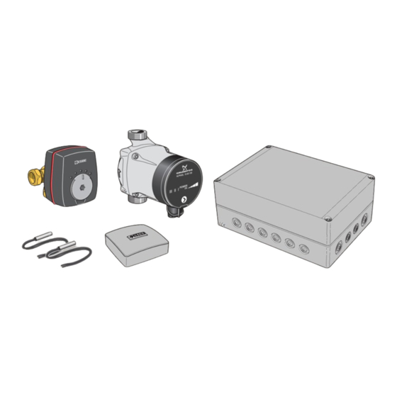
Page 13: Component Positions
Replacement gasket Temperature sensor Designations in component locations according to Room sensor standard IEC 81346-1 and 81346-2. Pipe with straight coupling* * This is only used when connecting to NIBE F370 or F470. Technical specifications Control voltage 230 V KV value... -
Page 14: Pipe Connections
Pipe connections Return General When connecting extra climate systems, they must be connected so that they have a lower working temperature Heat pump Flow pipe than the climate system 1. Circulation pump and mixing valve The extra circulation pump (GP20) is positioned in the extra climate system according to the outline diagram. -
Page 15: Outline Diagrams
Outline diagrams Pump and pressure drop diagrams, ECS 40 Available pressure NOTE These are outline diagrams. Actual installations must be planned according to applicable standards. Explanation EB100 Heat pump Temperature sensor, outdoor Temperature sensor, hot water Level vessel, brine Flow Flöde... - Page 16 Outline diagram F1145 with ECS 40/ECS 41 and up to three extra climate systems -EP23 -AA5 -BT2 -GP20 -BT3 -QN25 -EP22 -AA5 -BT2 -GP20 -BT3 -QN25 -EP21 -AA5 -BT2 -GP20 -BT3 -QN25 -EB100-BT1 -QM12 -EB100 -FL2 -CM2 -CM1 -QM42 -QM31...
- Page 17 Outline diagram F370/F470 with ECS 40/ECS 41 and up to three extra climate systems -EP23 -AA5 -BT2 -GP20 -BT3 -QN25 -EP22 -AA5 -BT2 -GP20 -EB100 -BT3 -QN25 -EP21 -AA5 -BT2 -GP20 -BT3 -QN25...
- Page 18 Outline diagram F750 with ECS 40/ECS 41 and up to three extra climate systems -EP23 -AA5 -BT2 -GP20 -BT3 -QN25 -EP22 -AA5 -BT2 -GP20 -BT3 -QN25 -EB100 -EP21 -AA5 -BT2 -GP20 -BT3 -QN25...
-
Page 19: Electrical Connection
The heat pump must not be powered when in- must be connected in series with the previous card. stalling ECS 40/ECS 41. Use cable type LiYY, EKKX or similar. The electrical circuit diagram is at the end of these install- ation instructions. -
Page 20: Connecting Sensors
Connecting sensors Connection of the mixing valve motor (QN25) Use cable type LiYY, EKKX or similar. Connect the mixing valve motor (QN25) to AA5-X9:6 (230 V, open), AA5-X9:5 (N) and AA5-X9:4 (230 V, close). Flow temperature sensor, extra climate system (BT2) Connect the flow temperature sensor to AA5-X2:23-24. -
Page 21: Program Settings
Program settings Caution Also see the Installer manual for relevant heat Program setting of ECS 40/ECS 41 can be performed via pump. the start guide or directly in the menu system. Start guide The start guide appears upon first start-up after heat pump installation, but is also found in menu 5.7. - Page 23 Bezeichnungen der Komponentenpositionen gemäß 2 St. Fühler Standard IEC 81346-1 und 81346-2. 1 St. Raumtemperaturfühler 1 St. Rohr mit gerader Kupplung* * Dies wird nur bei einem Anschluss an NIBE F370 oder F470 verwendet. Technische Daten Steuerspannung 230 V KV-Wert Ventilanschluss (Ø mm)
- Page 24 Rohranschluss/Durchflussmes- Rücklauf Allgemeines Wärmepumpe Vorlauf Bei Anschluss zusätzlicher Klimatisierungssysteme müssen diese so eingebunden werden, dass sie eine niedrigere Betriebstemperatur als Klimatisierungssystem 1 besitzen. Umwälzpumpe und Mischventil Die zusätzliche Umwälzpumpe (GP20) wird im zusätzli- chen Heiz- und Kühlkreis platziert (siehe Prinzipskizze). Fühler F1145/F1245/F750 Der Vorlauffühler (BT2) wird am Rohr zwischen Um-...
- Page 25 Prinzipskizzen Pumpenkennliniendiagramm, ECS 40 Verfügbarer Druck HINWEIS! Dies sind Prinzipskizzen. Die tatsächliche Anlage muss gemäß den gelten- den Normen geplant und montiert werden. Erklärung EB100 Wärmepumpe Außentemperaturfühler Fühler, Brauchwasser Niveaugefäß, Wärmequellenmedium Fluss Flöde Sicherheitsventil, Wärmequellenmedium 1000 1200 1400 1600 Schmutzfilter EP21 Heiz- oder Kühlkreis 2...
- Page 26 Prinzipskizze F1145 mit ECS 40/ECS 41 und bis zu drei zusätzlichen Klimatisierungssystemen -EP23 -AA5 -BT2 -GP20 -BT3 -QN25 -EP22 -AA5 -BT2 -GP20 -BT3 -QN25 -EP21 -AA5 -BT2 -GP20 -BT3 -QN25 -EB100-BT1 -QM12 -EB100 -FL2 -CM2 -CM1 -QM42 -QM31 -XL15 -EB100...
- Page 27 Prinzipskizze F370/F470 mit ECS 40/ECS 41 und bis zu drei zusätzlichen Klimatisierungssystemen -EP23 -AA5 -BT2 -GP20 -BT3 -QN25 -EP22 -AA5 -BT2 -GP20 -EB100 -BT3 -QN25 -EP21 -AA5 -BT2 -GP20 -BT3 -QN25...
- Page 28 Prinzipskizze F750 mit ECS 40/ECS 41 und bis zu drei zusätzlichen Klimatisierungssystemen -EP23 -AA5 -BT2 -GP20 -BT3 -QN25 -EP22 -AA5 -BT2 -GP20 -BT3 -QN25 -EB100 -EP21 -AA5 -BT2 -GP20 -BT3 -QN25...
-
Page 29: Elektrischer Anschluss
AA3-X4 zu verbinden. Die nächste Platine muss Die Wärmepumpe darf bei der Installation von mit der vorherigen in Reihe geschaltet werden. ECS 40/ECS 41 nicht mit Spannung versorgt Verwenden Sie Kabeltyp LiYY, EKKX oder gleichwertig. werden. Der Schaltplan befindet sich am Ende dieser Montagean- leitung. -
Page 30: Dip-Schalter
Fühleranschluss Anschluss des Mischventilmotors (QN25) Verwenden Sie Kabeltyp LiYY, EKKX oder gleichwertig. Verbinden Sie den Mischventilmotor (QN25) mit AA5- X9:6 (230 V, öffnen), AA5-X9:5 (N) und AA5-X9:4 (230 Vorlauffühler für zusätzlichen Heiz- oder Kühlkreis V, schließen). (BT2) Verbinden Sie den Vorlauffühler mit AA5-X2:23-24. Rücklauffühler für zusätzlichen Heiz- und Kühlkreis (BT3) Verbinden Sie den Rücklauffühler mit AA5-X2:21-22. - Page 31 Programmeinstellungen Menü 5.6 - Zwangssteuerung Zwangssteuerung der verschiedenen Komponenten und Die Programmeinstellung von ECS 40/ECS 41 kann per der einzelnen Zubehörteile, die eventuell angeschlossen Startassistent oder direkt im Menüsystem vorgenommen sind. EP21 ist Klimatisierungssystem 2, EP22 ist Klimatisie- werden. rungssystem 3, EP23 ist Klimatisierungssystem 4.
- Page 33 Elschema/Wiring diagram/Elektrischer schaltplan...
- Page 36 NIBE AB Sweden Hannabadsvägen 5 Box 14 SE-285 21 Markaryd Phone +46 433 73 000 Telefax +46 433 73 190 info@nibe.se www.nibe.se...
Need help?
Do you have a question about the ECS 40 and is the answer not in the manual?
Questions and answers