Nibe ECS 40 Installer Manual
Extra climate system for nibe f1145, f1245
Hide thumbs
Also See for ECS 40:
- Installer manual (144 pages) ,
- Manual (40 pages) ,
- Installer manual (17 pages)
Advertisement
Available languages
Available languages
Quick Links
Download this manual
See also:
Installation Manual
Installatörshansbok Extra Klimatsystem
SE
för NIBE F1145, F1245
Installer manual Extra climate system
GB
for NIBE F1145, F1245
Installateurhandbuch Extra mischgruppe
DE
für NIBE F1145, F1245
ECS 40
IHB 0935-1
031431
Advertisement

Related Manuals for Nibe ECS 40


Summary of Contents for Nibe ECS 40
- Page 1 ECS 40 Installatörshansbok Extra Klimatsystem för NIBE F1145, F1245 Installer manual Extra climate system for NIBE F1145, F1245 Installateurhandbuch Extra mischgruppe für NIBE F1145, F1245 IHB 0935-1 031431...
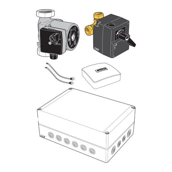
- Page 3 Svenska, Installatörshandbok - ECS 40 Innehåll Allmänt 4 st Buntband Detta tillbehör används då F1145/F1245 installeras i hus med upp till fyra olika klimatsystem som kräver olika 1 st Cirkulationspump framledningstemperaturer, t.ex. då huset har både radia- 1 st Shuntmotor torsystem och golvvärmesystem.
- Page 4 Temperaturgivare Röranslutning Framledningsgivaren (BT2) monteras på röret mellan cirkulationspumpen (GP20) och shuntventil (QN11). Cirkulationspump och shuntventil Returledningsgivaren (BT3) monteras på röret från Den extra cirkulationspumpen (GP20) placeras i det det extra klimatsystemet. extra klimatsystemet enligt principschema. Shuntventilen (QN25) placeras på framledningen efter värmepumpen, före första radiator på...
- Page 5 Klimatsystem 2 Smutsfilter EP22 Klimatsystem 3 QM31, Avstängningsventil QM32 EP23 Klimatsystem 4 QN25 Shuntventil, extra klimatsystem GP20 Cirkulationspump, extra klimatsystem Principschema F1145 med ECS 40 och två klimatsystem -EP21 -BT2 -GP20 -BT3 -QN11 -BT1 -FL2 -CM1 -QM31 -HQ1 -CP1 -QM32...
- Page 6 Principschema F1145 med ECS 40 och tre klimatsystem -EP22 -BT2 -GP20 -BT3 -QN11 -EP21 -GP20 -BT2 -QN11 -BT3 -BT1 -FL2 -CM1 -QM31 -HQ1 -CP1 -QM32 -EB100 -BT6 F1145 Principschema F1145 med ECS 40 och fyra klimatsystem -EP23 -BT2 -GP20 -BT3...
- Page 7 Principschema F1245 med ECS 40 och två klimatsystem -EP21 -BT2 -GP20 -BT1 -BT3 -QN11 -FL2 -CM1 -QM31 -HQ1 -QM32 -EB100 F1245 Principschema F1245 med ECS 40 och tre klimatsystem -EP22 -BT2 -GP20 -BT3 -QN11 -EP21 -GP20 -BT1 -BT2 -QN11 -BT3...
- Page 8 Principschema F1245 med ECS 40 och fyra klimatsystem -EP23 -BT2 -GP20 -BT3 -QN11 -EP22 -BT2 -GP20 -BT3 -QN11 -EP21 -GP20 -BT1 -BT2 -QN11 -BT3 -FL2 -CM1 -QM31 -HQ1 -QM32 -EB100 F1245...
- Page 9 Elektrisk installation och ledningsdragning skall AA3-X4 utföras enligt gällande bestämmelser. AA3-X4 F1145/F1245 ska vara spänningslös vid installa- tion av ECS 40. Elscheman finns i slutet av denna monteringsanvisning. AA3-X4 Anslutning av matning Anslut spänningsmatningen till plint X1 enligt bild. 230V 50Hz...
- Page 10 Anslutning av givare Anslutning av shuntmotor (QN25) Använd kabeltyp LiYY, EKKX eller likvärdig. Anslut shuntmotorn (QN25) till AA5-X9:6 (230 V, öppna), AA5-X9:5 (N) och AA5-X9:4 (230 V, stäng). Framledningsgivare, extra klimatsystem (BT2) Anslut framledningsgivaren till AA5-X2:23-24. Returledningsgivare, extra klimatsystem (BT3) Anslut returledningsgivaren till AA5-X2:21-22.
- Page 11 Programinställningar Programinställningen av ECS 40 kan göras via startguiden eller direkt i menysystemet. Startguiden Startguiden visas vid första uppstart efter värmepumpsin- stallationen, men finns även i meny 5.7. Menysystemet Om du inte gör alla inställningar via startguiden eller be- höver ändra någon inställning kan du göra detta i meny- systemet.
- Page 13 English, Installer manual - ECS 40 Contents General Cable ties This accessory is used when F1145/F1245 is installed in houses with up to four different climate systems that re- Circulation pump quire different flow line temperatures, for example, in Shunt motor cases where the house has both a radiator system and an under floor heating system.
-
Page 14: Temperature Sensor
Temperature sensor Pipe connections The flow temperature sensor (BT2) is installed on the pipe between the circulation pump (GP20) and mixing Circulation pump and mixing valve valve (QN11). The extra circulation pump (GP20) is positioned in the The return line sensor (BT3) is installed on the pipe extra climate system according to the outline diagram. - Page 15 Climate system 3 QM31, Shut-off valve QM32 EP23 Climate system 4 QN25 Mixing valve, extra climate system GP20 Circulation pump, extra climate system Outline diagram F1145 with ECS 40 and two climate systems -EP21 -BT2 -GP20 -BT3 -QN11 -BT1 -FL2 -CM1 -QM31...
- Page 16 Outline diagram F1145 with ECS 40 and three climate systems -EP22 -BT2 -GP20 -BT3 -QN11 -EP21 -GP20 -BT2 -QN11 -BT3 -BT1 -FL2 -CM1 -QM31 -HQ1 -CP1 -QM32 -EB100 -BT6 F1145 Outline diagram F1145 with ECS 40 and four climate systems...
- Page 17 Outline diagram F1245 with ECS 40 and two climate systems -EP21 -BT2 -GP20 -BT1 -BT3 -QN11 -FL2 -CM1 -QM31 -HQ1 -QM32 -EB100 F1245 Outline diagram F1245 with ECS 40 and three climate systems -EP22 -BT2 -GP20 -BT3 -QN11 -EP21 -GP20...
- Page 18 Outline diagram F1245 with ECS 40 and four climate systems -EP23 -BT2 -GP20 -BT3 -QN11 -EP22 -BT2 -GP20 -BT3 -QN11 -EP21 -GP20 -BT1 -BT2 -QN11 -BT3 -FL2 -CM1 -QM31 -HQ1 -QM32 -EB100 F1245...
- Page 19 F1145/F1245 out in accordance with the stipulations in force. AA3-X4 AA3-X4 F1145/F1245 must not be powered when in- stalling ECS 40. The electrical circuit diagram is at the end of these install- ation instructions. AA3-X4 Connecting the supply Connect the power supply to terminal block X1 as illus- trated.
- Page 20 Connecting sensors Connection of the mixing valve motor (QN25) Use cable type LiYY, EKKX or similar. Connect the mixing valve motor (QN25) to AA5-X9:6 (230 V, open), AA5-X9:5 (N) and AA5-X9:4 (230 V, close). Flow temperature sensor, extra climate system (BT2) Connect the flow temperature sensor to AA5-X2:23-24.
- Page 21 Program settings Program setting of ECS 40 can be performed via the start guide or directly in the menu system. Start guide The start guide appears upon first start-up after heat pump installation, but is also found in menu 5.7.
- Page 23 Deutsch, Installateurhandbuch - ECS 40 Inhalt Allgemeines 4 St. Kabelbinder Dieses Zubehör wird eingesetzt, wenn F1145/F1245 in einem Haus mit bis zu vier verschiedenen Heiz- und 1 St. Umwälzpumpe Kühlkreisen installiert ist, die mit unterschiedlichen Vor- 1 St. Mischventilmotor lauftemperaturen betrieben werden sollen, z.B. wenn ein Gebäude über Heizkörper und Fußbodenheizung verfügt.
- Page 24 Fühler Rohranschluss/Durchflussmes- Der Vorlauffühler (BT2) wird am Rohr zwischen Um- wälzpumpe (GP20) und Mischventil (QN11) montiert. Der Rücklauffühler (BT3) wird am Rohr vom zusätzli- Umwälzpumpe und Mischventil chen Heiz- und Kühlkreis montiert. Die zusätzliche Umwälzpumpe (GP20) wird im zusätz- lichen Heiz- und Kühlkreis platziert (siehe Prinzipskiz- ze).
- Page 25 QM31, Absperrventil QM32 EP23 Heiz- oder Kühlkreis 4 QN25 Mischventil für zusätzlichen Heiz- oder Kühlkreis GP20 Umwälzpumpe für zusätzlichen Heiz- oder Kühlkreis Prinzipskizze F1145 mit ECS 40 sowie zwei Heiz- oder Kühlkreisen -EP21 -BT2 -GP20 -BT3 -QN11 -BT1 -FL2 -CM1...
- Page 26 Prinzipskizze F1145 mit ECS 40 sowie drei Heiz- oder Kühlkreisen -EP22 -BT2 -GP20 -BT3 -QN11 -EP21 -GP20 -BT2 -QN11 -BT3 -BT1 -FL2 -CM1 -QM31 -HQ1 -CP1 -QM32 -EB100 -BT6 F1145 Prinzipskizze F1145 mit ECS 40 sowie vier Heiz- oder Kühlkreisen...
- Page 27 Prinzipskizze F1245 mit ECS 40 sowie zwei Heiz- oder Kühlkreisen -EP21 -BT2 -GP20 -BT1 -BT3 -QN11 -FL2 -CM1 -QM31 -HQ1 -QM32 -EB100 F1245 Prinzipskizze F1245 mit ECS 40 sowie drei Heiz- oder Kühlkreisen -EP22 -BT2 -GP20 -BT3 -QN11 -EP21 -GP20...
- Page 28 Prinzipskizze F1245 mit ECS 40 sowie vier Heiz- oder Kühlkreisen -EP23 -BT2 -GP20 -BT3 -QN11 -EP22 -BT2 -GP20 -BT3 -QN11 -EP21 -GP20 -BT1 -BT2 -QN11 -BT3 -FL2 -CM1 -QM31 -HQ1 -QM32 -EB100 F1245...
- Page 29 Anschluss der Kommunikationsleitung Elektrischer Anschluss Die erste Zusatzplatine ist direkt mit der Wärmepumpen- klemme AA3-X4 zu verbinden. Bei mehreren Zusatzplati- HINWEIS! nen muss die folgende Platine mit der vorherigen in Reihe Alle elektrischen Anschlüsse müssen von einem geschaltet werden. geprüften Elektriker ausgeführt werden. Verwenden Sie Kabeltyp LiYY, EKKX oder gleichwertig.
- Page 30 Fühleranschluss Anschluss des Mischventilmotors (QN25) Verwenden Sie Kabeltyp LiYY, EKKX oder gleichwertig. Verbinden Sie den Mischventilmotor (QN25) mit AA5- X9:6 (230 V, öffnen), AA5-X9:5 (N) und AA5-X9:4 (230 Vorlauffühler für zusätzlichen Heiz- oder Kühlkreis V, schließen). (BT2) Verbinden Sie den Vorlauffühler mit AA5-X2:23-24. Rücklauffühler für zusätzlichen Heiz- und Kühlkreis (BT3) Öffnen...
- Page 31 Programmeinstellungen Die Programmeinstellung von ECS 40 kann per Startassis- tent oder direkt im Menüsystem vorgenommen werden. Startassistent Der Startassistent erscheint bei der ersten Inbetriebnahme nach der Wärmepumpeninstallation. Er kann ebenfalls über Menü 5.7 aufgerufen werden. Menüsystem Wenn Sie nicht alle Einstellungen über den Startassistent vornehmen oder eine Einstellung ändern wollen, können...
- Page 33 Elschema/Wiring diagram/Elektrischer schaltplan...
- Page 36 NIBE AB Sweden Järnvägsgatan 40 Box 14 SE-285 21 Markaryd Phone +46 433 73 000 Telefax +46 433 73 190 info@nibe.se www.nibe.se...
Need help?
Do you have a question about the ECS 40 and is the answer not in the manual?
Questions and answers