SEW-Eurodrive MOVITRAC LTE-B Manual
Accessories - keypad, parameter module, cable sets
Hide thumbs
Also See for MOVITRAC LTE-B:
- Operating instructions manual (64 pages) ,
- Operating instructions manual (38 pages) ,
- Operating instructions manual (24 pages)

Related Manuals for SEW-Eurodrive MOVITRAC LTE-B


Summary of Contents for SEW-Eurodrive MOVITRAC LTE-B
- Page 1 *21326991_0515* Drive Technology \ Drive Automation \ System Integration \ Services Manual MOVITRAC ® LTE-B/LTP-B Accessories Keypads, Parameter Module, Cable Sets Edition 05/2015 21326991/EN...
- Page 2 SEW-EURODRIVE—Driving the world...
-
Page 3: Table Of Contents
Table of contents Table of contents General information ........................5 About this documentation ....................5 Rights to claim under limited warranty ................5 Other applicable documentation ..................5 Copyright notice ......................5 System overview ........................6 System overview of MOVITRAC ®... - Page 4 Table of contents Prefabricated cables with RJ45 connector on one end ..........30 Prefabricated cables with RJ45 connectors on both ends ........... 30 Control boards......................... 31 OB LT LOCMO control board ..................31 8.1.1 Technical data....................31 8.1.2 Installation..................... 32 8.1.3 Startup and operation ...................
-
Page 5: General Information
General information About this documentation General information About this documentation This documentation is an integral part of the product. The documentation is intended for all employees who perform assembly, installation, startup, and service work on the product. Make sure this documentation is accessible and legible. Ensure that persons respon- sible for the machinery and its operation as well as persons who work on the device independently have read through the documentation carefully and understood it. -
Page 6: System Overview
System overview System overview of MOVITRAC® LTE-B System overview System overview of MOVITRAC ® LTE-B System overview of MOVITRAC ® LTE-B Line Line filter NF Line choke HD ® Bluetooth Parameter module Option cards: LTBP-C 2nd relay output OB LT 2ROUTB PI controller OB LT PICON-B 2nd signal relay... -
Page 7: System Overview Of Movitrac Ltp-B
System overview System overview of MOVITRAC® LTP-B System overview of MOVITRAC ® LTP-B System overview of MOVITRAC ® LTP-B 3 × 200 – 240 V, 3 × 380 – 480 V 1 × 200 – 240 V 3 × 500 – 600 V Option cards: Relay outputs OBLT 3ROUT-A... -
Page 8: Parameter Module
Parameter module Parameter module Parameter module Parameter module The parameter module is exclusively designed for operation in the RJ45 port of the frequency inverter. Type Part number LTE-B LTP-B LTBP-C 18241549 X = available − = not available 9007202440910859 • Functionality: –... -
Page 9: Installation, Startup, And Operation
Parameter module Installation, startup, and operation Installation, startup, and operation 3.2.1 Directly at the frequency inverter 1. Check the frequency inverter connection. 2. Remove the protection caps from the parameter module and insert the parameter module into the frequency inverter slot RJ45. 13663204747 13642864139 Status LEDs... - Page 10 Parameter module Installation, startup, and operation If the frequency inverter display shows PASS-t, the parameter set was successfully copied to the frequency inverter. Locking or unlocking the parameter module The parameter module is equipped with a locking switch [5] with 2 positions. 1.
-
Page 11: With Lt Shell Software
Parameter module Installation, startup, and operation 3.2.2 With LT Shell software Parameterization user interface A Bluetooth ® interface at the PC is required for communication with PC. [10] [11] [12][13] 12804199691 Tool selection menu: Transfer parameter set from parameter module •... - Page 12 Parameter module Installation, startup, and operation 6. Start the software LT-Shell V4.0.exe. 7. The parameter editor is displayed. 8. Select the COM port of the PC/laptop to which the frequency inverter is connected via the parameter module. 13102428043 ® 9. Choose the communication Bluetooth 13642995211 10.Scan the network for existing drives [11].
- Page 13 Parameter module Installation, startup, and operation 12.Transfer the parameter set from the software to the frequency inverter using the button [6] or to the parameter module using the button [8]. 13.Double-click the parameter you want to change. 14.Enter the new parameter value into the edit box. Manual –...
-
Page 14: Keypad
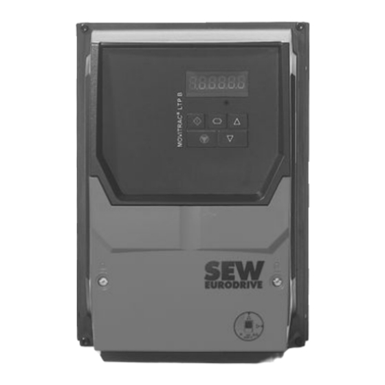
Keypad Keypad Each MOVITRAC ® LT inverter is equipped with a keypad as standard, which allows for operating and setting up the frequency inverter without the use of any further devices. 2933664395 [1] 6-digit 7-segment display [4] Navigate key [2] Start key [5] Up key [3] Stop/reset key [6] Down key... -
Page 15: Remote Keypads
Remote keypads LT BG-C remote keypad Remote keypads The MOVITRAC ® LT basic unit has an integrated keypad. Some applications require a remote keypad of the frequency inverter. The keypad option comes equipped with a self-adhesive gasket and a 3 m cable, which is plugged into the RJ45 socket of fre- quency inverter. -
Page 16: Installation In The Control Cabinet Or Control Panel
Remote keypads LT BG-C remote keypad 5.1.1 Installation in the control cabinet or control panel For installing an LT BG-C in the door of a control cabinet or in a control panel, the metal has to be cut as shown in the illustration below. The installed keypad meets standard IP54/NEMA 13 if the self-adhesive gasket enclosed in the delivery is used. -
Page 17: Technical Data
Remote keypads LT BG-C remote keypad 5.1.2 Technical data Unit connections RJ45 Supply voltage DC 24 V ±10% Supply current 30 mA Degree of protection IP20 (if not installed in the control cabinet) IP54 / NEMA 13 (if installed in the control cabi- net door) Ambient temperature during opera- 0 to +50 °C... -
Page 18: Lt Zbg Oled A Remote Keypad
Remote keypads LT ZBG OLED A remote keypad LT ZBG OLED A remote keypad We offer a full text OLED keypad as an additional option. Type Part number LTE-B LTP-B LT ZBG OLED A 28205731 X = available − = not available 9661213707 5.2.1 Installation in the control cabinet or control panel... -
Page 19: Technical Data
Remote keypads LT ZBG OLED A remote keypad 5.2.2 Technical data Unit connections RJ45 Supply voltage DC 24 V ±10% Supply current 30 mA Degree of protection IP20 (if not installed in the control cabinet) IP54 / NEMA 13 (if installed in the control cabi- net door) Ambient temperature during opera- -10 to +50 °C... -
Page 20: Electrical Installation
Remote keypads Electrical installation Electrical installation The remote keypad can be connected directly to the frequency inverter using a stand- ard RJ45 cable. Voltage supply and data transmission is realized via the interface. The socket at the keypad: 13515899787 [1] Not connected [2] Not connected [3] 0 V [4] RS485- (engineering) -
Page 21: System Structure
Remote keypads System structure System structure As soon as the physical connection is established, the keypad can be used. The key- pad supports a network with different LT frequency inverter via the respective commu- nication address. See "Setting the communication address" (→ 2 22). A maximum of 2 keypads may be integrated into an existing network. -
Page 22: Startup
Remote keypads Startup Startup 5.5.1 Setting the communication address The remote keypad tries to reach the frequency inverter with address 1 during the first startup. After the startup, "SCAN.." is displayed. The remote keypad scans the network for fre- quency inverters with address 1. If the frequency inverter was found, the message "Load.."... -
Page 23: Speed Change In Real Time Mode With Remote Keypad
Remote keypads Startup • To start the drive with the preset speed, set the parameter: – P-31 to 1 or 3 with LTE-B – P2-37 to 1 or 3 with LTP-B. • If the drive is at a standstill, press the <Stop> key. The value of the digital potenti- ometer (≙... -
Page 24: Direction Of Rotation Reversal
Remote keypads Startup 5.5.5 Direction of rotation reversal • For unipolar or bipolar control of the drive with the remote keypad, set the parame- ter: – P-12 to 1 or 2 with LTE-B – P1-12 to 1 or 2 with LTP-B. •... -
Page 25: Network Packages
Network packages Basic package (cable set A) Network packages For a network connection between MOVITRAC ® LTE-B or LTP-B and a gateway in a UOx housing, network packages with respective components are available. Basic package (cable set A) The basic package (cable set A) contains all components to connect the frequency in- ®... -
Page 26: Extension Package (Cable Set B)
Network packages Extension package (cable set B) Extension package (cable set B) The extension package is used in addition to the basic package (cable set A) to con- nect more frequency inverters in the network. Cable set B also contains a heat shrink tubing for insulation of the cable splitter. -
Page 27: Pc Engineering Package (Cable Set C)
Network packages PC engineering package (cable set C) PC engineering package (cable set C) This cable set is used to connect the inverters to the engineering software LT Shell for software updates or for configuration purposes. In addition, an USB11A interface adapter is required. -
Page 28: Example 2
Network packages PC engineering package (cable set C) 6.3.2 Example 2 This shows the use of cable set C within an existing fieldbus network. LTP-B 1 LTP-B n-1 LTP-B n DHP 11B L1/L L2/N L3 L1/L L2/N L3 L1/L L2/N L3 1 2 3 4 5 6 7 8 9 10 11 12 13 1 2 3 4 5 6 7 8 9 10 11 12 13 1 2 3 4 5 6 7 8 9 10 11 12 13... - Page 29 Network packages Cable splitter 1 to 2 Cable splitter 1 to 2 Type Part number LTE-B LTP-B LT-RJ-CS-21-C 28201140 X = available − = not available 9007204376907403 The RJ cable splitter is required to connect the RJ45 communication interface of the MOVITRAC ®...
-
Page 30: Prefabricated Cables
Prefabricated cables Prefabricated cables with RJ45 connector on one end Prefabricated cables Prefabricated cables with RJ45 connector on one end Each cable is equipped with an 8-pin RJ45 connector on one end. These cables are ® used for connecting the MOVITRAC LT to the DFx gateway. -
Page 31: Control Boards
Control boards OB LT LOCMO control board Control boards OB LT LOCMO control board Type Part number LTE-B LTP-B OB LT LOCMO 18205607 – X = available − = not available Using a control board is an additional way of enabling frequency inverters via termi- nals or controlling the speed. -
Page 32: Installation
Control boards OB LT LOCMO control board 8.1.2 Installation WARNING Electric shock due to charged capacitors. Dangerous voltage levels may still be present inside the unit and at the terminals up to ten minutes after disconnection from the power supply. Severe or fatal injuries. -
Page 33: Ltzoblocmob Control Board
Control boards LTZOBLOCMOB control board LTZOBLOCMOB control board Type Part number LTE-B LTP-B LTZOBLOCMOB 28205758 – X = available − = not available The control board allows the user to operate the frequency inverter easily and quickly via the terminal control on site. The control board is connected to the 13-pin terminal and supplied with 24 V via terminal 1. -
Page 34: Installation
Control boards LTZOBLOCMOB control board 8.2.2 Installation WARNING Electric shock due to charged capacitors. Dangerous voltage levels may still be present inside the unit and at the terminals up to ten minutes after disconnection from the power supply. Severe or fatal injuries. •... -
Page 35: Index
Index Index Cable set A............25 Cable set B............26 Cable set C ............27 Cable splitter 1 to 2 ..........29 Cable with RJ45 connector (one end)....30 Cable with RJ45 connectors (both ends) ..... 30 Control board ..........31, 33 Copyright notice ............. - Page 40 SEW-EURODRIVE—Driving the world SEW-EURODRIVE GmbH & Co KG P.O. Box 3023 76642 BRUCHSAL GERMANY Phone +49 7251 75-0 Fax +49 7251 75-1970 sew@sew-eurodrive.com www.sew-eurodrive.com...
Need help?
Do you have a question about the MOVITRAC LTE-B and is the answer not in the manual?
Questions and answers