
Subscribe to Our Youtube Channel
Related Manuals for Sensopart FT 80 RLA Series


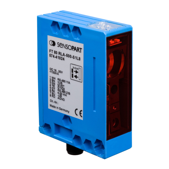
Summary of Contents for Sensopart FT 80 RLA Series
- Page 1 Montage- und Bedienungsanleitung Mounting and operating instructions Instructions de service et de montage FT 80 RLA 500-L8 500-S1L8 Abstandssensor Distance sensor Capteur de distance...
- Page 2 Toute reproduction de ce document, ainsi que son enregistrement dans une base ou système de données ou sa publication, sous quelque forme que ce soit, même par extraits, ainsi que la contrefaçon des dessins et de la mise en page ne sont pas permises sans l’autorisation explicite et écrite de SensoPart France Industriesensorik GmbH.
- Page 3 Maßzeichnung / Dimensional drawing / Plan coté Abb. 1 / Illustr. 1 / Fig. 1 15300356 Anschluss / Wiring / Raccordement Typ / Type / Ref. Pin 1 Pin 5 FT 80 RLA 500 -S1L8. RS485 Y/A RS485 Z/B FT 80 RLA 500 -L8. N.C.
- Page 4 Inhalt / Content / Contenu Deutsch ........................5 English ........................25 Français ......................... 45...
-
Page 5: Table Of Contents
Montage- und Bedienungsanleitung Inhaltsverzeichnis Zeichenerklärung ............................5 Sicherheitshinweise ............................6 Einsatzzweck ..............................7 Leistungsmerkmale ............................7 Funktionsweise ..............................7 Montage.................................8 Elektrische Installation ..........................9 Bedienung ..............................10 Allgemeine Bedienung..........................10 Einstellungen ..............................12 Funktionen ..............................12 Reset ................................14 Tasten entriegeln ............................14 Mittelwertbildung............................15 Modus Autozero............................15 Modus Autocenter............................16 Modus Maximum-Hold..........................16 Modus Differenz-Hold ..........................17 Modus Messwert-Hold ..........................17 Modus Differenzmessung ..........................18 Anwendungsbeispiele..........................19... -
Page 6: Zeichenerklärung
Montage- und Bedienungsanleitung Zeichenerklärung Achtung Dieses Symbol kennzeichnet Textstellen, die unbedingt zu beachten sind. Die Nichtbeachtung kann zu Personen- oder Sachschäden führen. Achtung Laser Dieses Symbol steht vor Textstellen, die vor Gefahren durch Laserstrahlen warnen. Hinweis Dieses Symbol kennzeichnet Textstellen, die nützliche Informationen enthalten. Sicherheitshinweise Vor der Inbetriebnahme des FT 80 RLA diese Anleitung, insbesondere die Sicherheitshinweise, lesen, verstehen und unbedingt beachten. -
Page 7: Einsatzzweck
Montage- und Bedienungsanleitung Einsatzzweck Für das Sichern von Personen an Maschinen und technischen Anwendungen ist der FT 80 RLA nicht zugelassen. Der FT 80 RLA ist ein optischer Sensor und misst berührungslos Abstände. In der Kombination (siehe Anwendungs- beispiele) mit einem zweiten FT 80 RLA können auch Objektdicken gemessen werden (nur mit -S1 Typen möglich, siehe „Bestellinformationen“... -
Page 8: Montage
Montage- und Bedienungsanleitung Lichtfleckgeometrie FT 80 RLA 500... 250 mm 750 mm 1.9 mm x 1.2 mm 2.7 mm x 1.9 mm Alle Maße in Millimeter Abb. 4 15500157 Montage Sensoranordnung Den FT 80 RLA positionieren, so dass der Abstand zum Objekt innerhalb des Arbeitsbereiches vom Sensor liegt. Den FT 80 RLA auf den Haltewinkel, z.B. -
Page 9: Elektrische Installation
Montage- und Bedienungsanleitung Elektrische Installation Achtung: Pin 1 und Pin 5 dürfen nicht an die Betriebsspannung angeschlossen werden. Bei Nichtbeachtung wird der FT 80 RLA zerstört. Gerätestecker für das Anschlusskabel entsprechend der Einbaulage so verdrehen (Abb. 1, Seite 3), dass das An- schlusskabel frei und ohne abzuknicken angeschlossen werden kann. -
Page 10: Bedienung
Montage- und Bedienungsanleitung Bedienung Bedienfeld Der FT 80 RLA hat verschiedene Betriebsarten. Mit den Tasten S und T wird der FT 80 RLA konfiguriert. Taste Set-Taste: Einstellung ändern bzw. bestätigen oder Schaltpunkt teachen. Toggle-Taste: Funktion auswählen Die Kennzeichnung der gewählten Einstellungen und des Signalzustands erfolgt durch LEDs. Farbe Verwendung / Beschreibung Grün... - Page 11 Montage- und Bedienungsanleitung Findet kein Wechsel statt: T-Taste länger gedrückt halten. Nach der letzten Funktion folgt wieder die erste Funktion. Wurde versehentlich die falsche Funktion gewählt, ist ein direkter Schritt zurück zur letzten Funktionsnummer nicht möglich. T-Taste mehrmals drücken, bis die gewünschte Funktion wieder erscheint. Oder, Einstellmodus deaktivieren (siehe 4.) und Vorgang ab 1.
-
Page 12: Einstellungen
Montage- und Bedienungsanleitung Einstellungen Der FT 80 RLA kann mit den Funktionen 1 bis 26 im Einstellmodus (Teach In) konfiguriert werden. Taste Set-Taste: Einstellung ändern bzw. bestätigen oder Schaltpunkt teachen. Toggle-Taste: Funktion auswählen Funktionen Nr. LED Muster Beschreibung Zustandsanzeige „ZA“ Werkseinstellung Modus Ausgang Q wählen... - Page 13 Montage- und Bedienungsanleitung Nr. LED Muster Beschreibung Zustandsanzeige „ZA“ Werkseinstellung Modus Q1=Triggereingang: Ein = Q ist ein Triggereingang Mit steigender Flanke an Q wird der Aus = Q ist kein Triggereingang Messwert bis zum nächsten Triggerer- eignis festgehalten. Modus Q1=Enable-Eingang: Ein = aktiv Dient zum Ein- und Ausschalten des Aus = inaktiv...
-
Page 14: Reset
Montage- und Bedienungsanleitung Nr. LED Muster Beschreibung Zustandsanzeige „ZA“ Werkseinstellung Modus Maximum-Hold Q Ein = Maximum-Hold aktiv inaktiv Solange an Q anliegt, wird der Aus = Maximum-Hold inaktiv maximal auftretende Messwert gespei- chert. Wenn an Q anliegt, wird der ermittelte Wert am Analog ausgang ausgegeben. -
Page 15: Mittelwertbildung
Montage- und Bedienungsanleitung Mittelwertbildung Das Messergebnis (Ausgangssignal) wird durch die Mittelwertbildung geglättet. Hierfür werden die Messwerte fort- laufend in einen Speicher gelesen und das arithmetische Mittel gebildet. Die Funktionen 14 und 15 (Seite 13) legen die Anzahl der Messungen (10 oder 100), die zur Mittelwertbildung verwendet werden, fest. Durch die Abtastrate von 0,4 ms pro Messung liegt die Ansprechzeit zwischen 0,4 ms (ohne Mittelwertbildung) und 40 ms. -
Page 16: Modus Autocenter
Montage- und Bedienungsanleitung Modus Autocenter Die Ausgangskennlinie 4 – 20 mA wird mit dieser Funktion verschoben. Ist die Funktion Autocenter aktiviert und wird an Q angelegt, wird der aktuelle Messwert mit dem Ausgangswert von 50% = 12 mA gleichgesetzt. Die Steigung der Kennlinie bleibt gleich und der Minimal- und Maximalwert der Kennlinie wird durch den Messbereich begrenzt. -
Page 17: Modus Differenz-Hold
Montage- und Bedienungsanleitung Modus Differenz-Hold Ist die Funktion Differenz-Hold aktiviert und wird an Q die Spannung +U angelegt, wird mit dieser Funktion die Differenz von Minimal- und Maximalwert des Messsignals bestimmt und gespeichert. Wird an Q , -U angelegt, wird der letzte Differenzwert am Analogausgang ausgegeben. Anwendungsbeispiel: Inhalt von offenen Behältern oder Paketen prüfen. -
Page 18: Modus Differenzmessung
Montage- und Bedienungsanleitung Modus Differenzmessung Zur Differenzmessung können ausschließlich FT 80 RLA in der Ausführung S1 benutzt werden. Ein gleichzeitiger Anschluss zu einer SPS-Steuerung oder einem Personal Computer über die RS 485 –Schnittstelle ist bei der Differenzmessung nicht möglich. Bei diesem Messverfahren werden zwei FT 80 RLA -S1 miteinander gekoppelt. Die Messbereiche können dabei überlappen 1, direkt angrenzen 2 oder auseinanderliegen 3 (Abb. -
Page 19: Anwendungsbeispiele
Montage- und Bedienungsanleitung 4. Referenz Objekt mit bekannter Breite in den Messbereich einlegen Achtung: LED „OK“ (Good Target) muss bei beiden Sensoren leuchten. 5. Zweiten FT 80 RLA -S1 als Master konfigurieren, dazu Funktion Nr. 25 (Seite 14) aktivieren. Achtung: Sensor lässt sich nur als Master konfigurieren, wenn sich das Objekt bei beiden Sensoren innerhalb des Messbereichs befindet (siehe 4.) 6. -
Page 20: Sensorkonfiguration Mit Der Software Progsensor
Zur komfortablen Parametrierung der Sensortypen S1 ist eine Bediensoftware „ProgSensor“ lieferbar, die im Simula- tionsmodus auch die für den jeweiligen Fall korrekten Busbefehle anzeigt. Siehe Hinweise hierzu auf unserer Homepage: www.sensopart.de und in den Bestellinformationen auf Seite 24. Übertragungsprotokoll Übertragungsrahmen (frame) Die busfähige RS 485 Schnittstelle des FT 80 RLA Typ S1 arbeitet im Halbduplex-Mode (1 Stoppbit. -
Page 21: Busbefehle
Montage- und Bedienungsanleitung Busbefehle Befehl Befehl Master- Parameter (ASCII) Bezeichnung (4. Byte und folgende) hex 3. Byte Highbyte Schaltpunkt 1, siehe 1) Seite 22.. Lowbyte Schaltpunkt 1, siehe 1) Seite 22.. Konfiguration: D0: 1 = Schließer, 0 = Öffner D1: 1 = Impulsverlängerung, Schaltausgang Q 0 = Aus, siehe 2) Seite 22. -
Page 22: Erklärungen Zu Den Busbefehlen
Montage- und Bedienungsanleitung Erklärungen zu den Busbefehlen 1) Highbyte Lowbyte D0 - D11 = Abstandswert 0 - 4095 (entsprechend des eingestellten Messbereiches) 2) Byte 3) Highbyte Lowbyte D0 - D11 = Abstandswert (0 - 4095) Q1 = Zustand von Q1 GT = Good Target 4) Highbyte Lowbyte... - Page 23 Montage- und Bedienungsanleitung Optische Daten (typ.) Arbeitsbereich FT 80 RLA-500 250 ... 750 mm Messbereich FT 80 RLA-500 500 mm Auflösung <0,1% vom Messbereich Linearität <0,25% vom Messbereich Gepulstes Laserlicht, rot 650 nm, MTBF>50.000h * 1 Lichtart Impulsbreite Tp = 20 µs Impulswiederholfrequenz f = 2,5 kHz Max.
-
Page 24: Bestellinformationen
K2-ADE-TB* zu verwenden. Verfügt Ihr PC über eine USB Schnittstelle benötigen Sie zusätzlich das USB-RS 232 Schnittstel- lenkabel CUSB-RS232-2m*. *Artikelnummer siehe Zubehörliste Datenblätter, Bedienungsanleitungen und Software stehen unter www.sensopart.de zum Download bereit. FT 80 RLA Abstandssensor - 068-13715 - 04.05.2009-03... - Page 25 Mounting and operating instructions Table of contents Signs and Symbols ............................25 Safety information ............................26 Appropriate use ............................27 Performance characteristics ........................27 Mode of function ............................27 Mounting ..............................28 Electrical installation ...........................29 Instructions of use ............................30 General use ..............................30 Settings................................32 Functions ..............................32 Reset ................................34 Unlocking keys ............................34 Averaging ..............................35 Automatic zero mode...........................35...
-
Page 26: Signs And Symbols
Mounting and operating instructions Signs and Symbols Warning This symbol signals passages in the manual which must be observed at all times. Non-compliance can cause injuries or material damage. Warning Laser This symbol appears in front of warning passages concerning the danger of laser beams. Information This symbol signals passages with useful information. -
Page 27: Appropriate Use
Mounting and operating instructions Appropriate use The FT 80 RLA sensor is not authorised for use in protecting human safety on machines and during technical applications. The FT 80 RLA is an optical sensor and measures distances without contact. When combined (see examples of use) with another FT 80 RLA sensor, the thickness of objects can also be measured (only possible with S1 versions, see “Order information”, page 44). -
Page 28: Mounting
Mounting and operating instructions Dimensions of light spot FT 80 RLA 500... 250 mm 750 mm 1.9 mm x 1.2 mm 2.7 mm x 1.9 mm All dimensions in mm Illustr. 4 15500157 Mounting Sensor alignment Position 3RG7056 in a way that the distance to the object is within the working range of the sensor. Screw the FT 80 RLA sensor to the mounting bracket, e.g. -
Page 29: Electrical Installation
Mounting and operating instructions Electrical installation Warning: Pin 1 and pin 5 must not be connected to operational voltage as this will destroy the FT 80 RLA sensor. Turn the sensor connector plug according to the installation position (Illustr. 1 page 3) so that the connection cable can be freely connected without being bent. -
Page 30: Instructions Of Use
Mounting and operating instructions Instructions of use Control panel The FT 80 RLA has various modes and is configured using the S and T buttons. Button Set button: Change / confirm a setting or set a switching point Toggle button: Select a function (proceed to the next function) The selected settings and signal condition are indicated by LEDs. - Page 31 Mounting and operating instructions If no change occurs: Press T button for longer The first function follows the last available function. If the wrong function is selected by mistake, it is not possible to jump directly back to the pre- vious function number.
-
Page 32: Settings
Mounting and operating instructions Settings The FT 80 RLA sensor can be configured as follows with functions 1 to 26 in setting mode (teach-in). Button Set button: Change / confirm a setting or set a switching point Toggle button: Select a function (proceed to the next function) Functions No. - Page 33 Mounting and operating instructions No. LED Muster Description “ZA” status indicator Factory setting signal output shows status “good On = Object within... target”. Switching signal can be inverted Off = Object outside... with function no 8..measuring range = trigger input mode: On = Q is a trigger input With rising edge on Q...
-
Page 34: Reset
Mounting and operating instructions No. LED Muster Description “ZA” status indicator Factory setting maximum hold mode: On = Maximum hold active Not active Provided Off = Maximum hold not active = +U , the max. recorded measured value is stored. If Q = -U , the determined value is trans-... -
Page 35: Averaging
Mounting and operating instructions Averaging The measuring result (output signal) is smoothed by averaging. The measured values are read continuously into a memory and the arithmetical mean is formed. Functions 14 and 15 ( (page 33) determine the number of measure- ments (10 or 100) to be used for averaging. -
Page 36: Automatic Centre Mode
Mounting and operating instructions Automatic centre mode The output characteristic curve 4 – 20 mA is displaced with this function. When the automatic centre function is activated and Q = +U , the current measured value is equated with the output value of 50% = 12 mA. The incline of the characteristic curve is maintained and the minimum and maximum values of the characteristic curve are limited by the measuring range. -
Page 37: Difference Hold Mode
Mounting and operating instructions Difference hold mode When the difference hold function is activated and Q = +U , this function detects the difference between the mini- mum and maximum value of the measuring signal and stores it. If Q = -U , the last differential value is transmitted at the analogue output. -
Page 38: Differential Measurement Mode
Mounting and operating instructions Differential measurement mode Differential measurement can only be used with S1 version of FT 80 RLA. Simultaneous connection to SPC control or a PC via the RS 485 interface is not possible with differential measurement. With this measuring procedure, two FT80 RLA-S1 sensors are connected to one another. The measuring ranges can overlap (1), be directly adjacent (2) or apart (3) (Illustr. -
Page 39: Examples Of Use
Mounting and operating instructions 4. Insert reference object of known width in measuring range. Warning: LED “OK” (Good target) must light up on both sensors. 5. Configure the second FT 80 RLA-S1 sensor as the master. Activate function no. 25 (page 34). Warning: The sensor can only be configured as a master when the object is inside the measuring range of both sensors (see point 4). -
Page 40: Sensor Configuration With The Progsensor Software
The operating software “ProgSensor” is available to facilitate programming of versions S1. Its simulation mode indicates the correct bus commands for the respective case. For more information see our homepage: www.sensopart.de and the order information on page 44. Transmission protocol Transmission frame The bus-compatible RS 485 interface of FT 80 RLA version S1 operates in half-duplex mode (1 Stopbit, no parity). -
Page 41: Bus Commands
Mounting and operating instructions Bus commands Command Description Master parameters (ASCII) of command byte and following) hex byte High byte switching point 1 see 1) page 42 Low byte switching point 1 see 1) page 42 Configuration: D0: 1 = N.O., 0 = N.C D1: 1= pulse stretching Signal output Q 0 = off, see 2) page 42... -
Page 42: Explanations On Bus Commands
Mounting and operating instructions Explanations on bus commands 1) Highbyte Lowbyte D0 - D11 = distance value 0 - 4095 (according to the set measuring range) 2) Byte 3) Highbyte Lowbyte D0 - D11 = distance value (0 - 4095) Q1 = status of Q1 GT = Good Target 4) Highbyte... - Page 43 Mounting and operating instructions Optical data (typ.) Operating range FT 80 RLA-500 250 to 750 mm Measuring range FT 80 RLA-500 500 mm Resolution <0.1% of measuring range Linearity <0.25% of measuring range Light used Pulsed laser light, red 650 nm, MTBF>50,000h *1 Pulse width Tp = 20 µs Pulse repetition frequency...
-
Page 44: Order Information
If your PC has a USB interface, you will need in adition the interface cable CUSB-RS232-2m*. *See article number in accessories list above Data sheets, instruction manuals and software can be downloaded from www.sensopart.com FT 80 RLA Distance sensor - 068-13715 - 04.05.2009-03... - Page 45 Instructions de service et de montage Table des matières Légende des symboles..........................45 Consignes de sécurité ..........................46 Emploi................................47 Caractéristiques............................47 Principe de fonctionnement .........................47 Montage...............................48 Installation électrique ..........................49 Commande ..............................50 Commande générale ...........................50 Réglage ...............................52 Fonctions ..............................52 Reset - Initialisation .............................54 Déverrouillage des touches .........................54 Recherche de la moyenne...........................55 Mode Auto Zéro ............................55 Mode Auto Center............................56...
-
Page 46: Légende Des Symboles
Instructions de service et de montage Légende des symboles Attention Ce symbole est apposé aux textes qui doivent absolument être respectés. Le non-respect peut entraî- ner des dommages corporels ou matériels. Attention laser Ce symbole est apposé aux textes qui mettent en garde contre les dangers du laser. Information Ce symbole est apposé... -
Page 47: Emploi
Instructions de service et de montage Emploi Le FT 80 RLA n’est pas destiné à garantir la sécurité des personnes travaillant sur des machines et des applications techniques. Il s’agit d’un capteur optique qui mesure, sans contact, des distances. En doublon (voir Applications type), avec un second FT 80 RLA , il est possible de mesurer l’épaisseur d’un objet (uniquement avec les Types S1, voir „Références de commande“, page 64). - Page 48 Instructions de service et de montage Géométrie du spot FT 80 RLA 500... 250 mm 750 mm 1,9 mm x1,2 m 2,7 mm x 1,9 mm Toutes les dimensions en mm Fig. 4 15500157 Installation Positionnement du capteur Placer le FT 80 RLA de manière à ce que la distance séparant le capteur de l‘objet se trouve dans le champ de travail du capteur.
-
Page 49: Installation Électrique
Instructions de service et de montage Installation électrique Attention : Les broches 1 et 5 ne doivent pas être raccordés à l’alimentation sous peine de détruire le capteur. Tourner le capteur de telle façon (voir Fig. 1 page 3) que la fiche soit libre et que le connecteur puisse être monté sans être plié. -
Page 50: Commande
Instructions de service et de montage Commande Panneau de commande Le FT 80 RLA a plusieurs modes. A l’aide des touches S et T, le FT 80 RLA peut être configuré. Touche Touche Set (Réglage) : Changer / confirmer le réglage ou régler le point de commutation Touche Toggle (Bascule) : Sélectionner la fonction (accéder à... - Page 51 Instructions de service et de montage Si pas de changement : Appuyer plus longtemps sur la touche T Après la dernière fonction, la première se représente. Si par mégarde l’utilisateur a appuyé sur une mauvaise fonction, il n’est pas possible de retour- ner directement sur la dernière fonction réglée.
-
Page 52: Réglage
Instructions de service et de montage Réglage Le FT 80 RLA peut être configuré en mode Réglage (Teach-in) avec les fonctions 1 à 26. Touche Touche Set (Réglage) : Changer / confirmer le réglage ou régler le point de commutation Touche Toggle (Bascule) : Sélectionner la fonction (accéder à... - Page 53 Instructions de service et de montage N° LED Muster Désignation Témoin d’état „ZA“ Réglage usine Mode Q Entrée Déclenchement: Allumé = Q est une entrée Eteint Avec flanc montant en Q , la valeur de Déclenchement mesure est gardée jusqu’au prochain évé- Eteint = Q n’est pas une entrée nement Déclenchement...
-
Page 54: Reset - Initialisation
Instructions de service et de montage N° LED Muster Désignation Témoin d’état „ZA“ Réglage usine Mode Maintien Maximum Q Allumé = Maintien Maximum actif inactif aussi longtemps que +U est présente Eteint = Maintien Maximum en Q , la plus grande valeur mesurée inactif sera sauvegardée. -
Page 55: Recherche De La Moyenne
Instructions de service et de montage Recherche de la moyenne Le Résultat de mesure (signal de sortie) est aplani par la moyenne. Pour cela, les valeurs mesurées sont lues et stockées de manière continue sur une mémoire avec laquelle est constituée la moyenne arithmétique de ces données. -
Page 56: Mode Auto Center
Instructions de service et de montage Mode Auto Center La caractéristique de la sortie 4 - 20 mA se déplace avec cette fonction. Si cette fonction Auto Center est activée et que +U est appliquée en Q , la valeur actuelle mesurée est prise égale à la valeur de sortie de 50% = 12 mA. -
Page 57: Mode Maintien Différence
Instructions de service et de montage Mode Maintien Différence Si la fonction Hold Différence est activée et que la tension +U apparaît en Q , on peut déterminer et sauvegarder la différence entre le signal maximum et minimum. Si la tension -U apparaît en Q , la dernière différence est émise à... -
Page 58: Mode Mesure D'une Différence
Instructions de service et de montage Mode Mesure d’une différence On ne peut utiliser que des FT 80 RLA type S1 pour cette fonction. Une connexion simultanée à une commande à mémoire programmée ou à un PC par le biais d’une interface RS 485 n’est pas possible pour la mesure d’une différence. -
Page 59: Applications Type
Instructions de service et de montage Attention : LED „OK“ (Bonne cible) doit être allumée sur les deux capteurs. 5. Configurer le second capteur en tant que Maître; pour cela activer la fonction 25 (page 54). Attention : Le capteur ne se laisse configurer en tant que Maître que si l’objet se trouve à l’intérieur du champ pour les deux capteurs (voir 4.). -
Page 60: Configuration Capteur Avec Logiciel Progsensor
Pour un paramétrage confortable des capteurs type S1, il existe un logiciel d’utilisation „ProgSensor“ qui affiche en mode Simulation, pour chaone cas, les commandes Bus correctes. Merci de vous reporter pour ceci sur notre Site Internet : www.sensopart.fr et aux références de commande page 64. Protocole de transmission Cadre de transmission (frame) L’interface RS 485 compatible du FT 80 RLA travaille en mode Semi-duplex. -
Page 61: Commandes Bus
Instructions de service et de montage Commandes Bus Commande Description Paramètre Maître (ASCII) (5 ème octet et suivants) hex commande 3 ème octet Octet haut Point de commutation 1, voir 1) page 62 Octet bas Point de commutation 2, soir 1) page 62 Configuration: D0: 1 = Fermeture, 0 = Ouverture D1: 1 = Maintien au déclenchement,... -
Page 62: Annexe Commandes Bus
Instructions de service et de montage Annexe Commandes Bus 1) Octet haut Octet bas D0 - D11 = Valeur de distance 0 - 4095 (correspondant au champ de mesure) 2) Byte 3) Octet haut Octet bas D0 - D11 = Valeur de distance (0 - 4095) = Etat de Q1 GT = Bonne cible 4) Octet haut... - Page 63 Instructions de service et de montage Données optiques (typ.) Champ de travail FT 80 RLA - 500 250 ... 750 mm avec rémission 6% à 90% diffus Champ de mesure FT 80 RLA - 500 500 mm Résolution <0,1% du champ de mesure Linéarité...
-
Page 64: Références De Commande
Si votre PC dispose d‘une interface USB, vous devrez commander en plus un câble interface USB/RS232 CUSB - RS232-2m*. *Voir „Accessoires“ pour le n° d‘article Vous pouvez télécharger les fiches techniques, les manuels d’utilisation et le logiciel sous www.sensopart.fr FT 80 RLA Capteur de distance - 068-13715 - 04.05.2009-03... - Page 65 Kontaktadressen / Contact addresses / Contacts Deutschland France SensoPart Industriesensorik GmbH SensoPart France SARL Am Wiedenbach 1 11, rue Albert Einstein D-79695 Wieden Espace Mercure Tel.: +49 (0) 7665 - 94769 - 0 F-77420 Champs - Marne la Vallée Fax: +49 (0) 7665 - 94769 - 765 Tél.: +33 (0) 1 64 73 00 61...
Need help?
Do you have a question about the FT 80 RLA Series and is the answer not in the manual?
Questions and answers