
Subscribe to Our Youtube Channel
Related Manuals for Sensopart FT 50 C S1 Series


Summary of Contents for Sensopart FT 50 C S1 Series
- Page 1 Montage- und Bedienungsanleitung Mounting and operating instructions Instructions de service et de montage FT 50 C...S1 Farbsensor mit serieller Schnittstelle Colour sensor with serial interface Capteur de couleur avec interface série...
- Page 2 écrite de SensoPart Industriesensorik GmbH. Nous déclinons toute responsabilité concernent les fautes éventuelles d’impression et autres erreurs qui auraient pu intervenir lors du montage de cette brochure.
-
Page 3: Table Of Contents
Mounting and operating instructions Contents Guide to symbols ..............................35 Safety instructions ..............................35 Correct use .................................36 Performance ...............................36 Mounting ................................37 5.1 Dimensional drawing ..........................37 5.2 Mounting the sensor ..........................37 Electrical installation ............................38 Use and configuration ............................39 7.1 Displays and configuration elements ......................39 7.2 Possible configurations and operating modes ...................40 7.3 Configuration via the control panel ......................41 7.3.1 Quick user guide (068-13883) see fold-out page ................41... -
Page 4: Guide To Symbols
Mounting and operating instructions Guide to symbols Warnings and other information are signalled by symbols in this manual. They are accompanied by hea- dings. The following symbols are used: WARNING ... indicates a possibly dangerous situation which can cause death or serious injury if not avoided. CAUTION ... -
Page 5: Correct Use
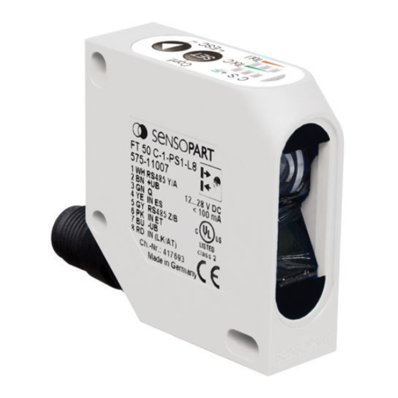
Mounting and operating instructions Correct use The FT 50 C...S1 is a colour sensor for the detection of objects in varying colours in proximity mode (for opaque objects) and reflector mode (for transparent objects). WARNING The FT 50 C must never be used to protect the safety of individuals or technical applications. Performance The colour sensors of the FT 50 C...S1 series are ideal for on-line colour detection in industrial procedures and processes. -
Page 6: Mounting
Mounting and operating instructions Mounting Dimensional drawing Illustr. 2 15300065 Illustr. 1 15300350 Mounting the sensor Screw sensor to suitable holder e.g. type MS F 50 or MSP F 50* (not included in delivery) using the fixing holes. Fit the sensor in a place where the distance to the object is as constant as possible (little variation in scanning distance). -
Page 7: Electrical Installation
Mounting and operating instructions Electrical installation Rotate the connector plug for the connection cable, so that the cable can be connected easily, without kinks. Fit socket of the connector cable and screw tight (authorised approx. tightening torque 0.5 to 1 Nm). Secure connection cable (for example with cable retainer). -
Page 8: Use And Configuration
Mounting and operating instructions Use and configuration The sensor has different operating modes and functions. It has a serial RS 485 interface for the transfer of colour values and configuration of sensor functions. Sensor configuration can be carried out via the control panel using the keys. -
Page 9: Possible Configurations And Operating Modes
Mounting and operating instructions Display function Colour In operating mode In configuration mode Yellow S = Scan No function FLASHES, Scan colour if menu „S“ (scan a colour) is selected, FLASHES with „+/F“, if menu „S+“ is selected Yellow C+ = Teach+ No function FLASHES with „C“, S+ = Scan+... -
Page 10: Configuration Via The Control Panel
Mounting and operating instructions Factory setting Also via the electrical interface: • It is possible to teach a reference colour via the external input cable „IN ET“ • It is possible to scan a colour range via the external input cable „IN ES“... - Page 11 Mounting and operating instructions Procedure: Step Menu item Activity Picture follows Remark Operating Position object Observe operating parameters such as scanning distance, mode (no direction of movement, inclination etc. (see chapter menu item) “Mounting“). Press LED „C“ (yellow) flashes, when time lock is open and configuration mode is activated.
-
Page 12: Menu „C+": Teach, Add, Link Further Colours
Mounting and operating instructions Teach-in colours via PIN 6: The teach-in procedure can also be initiated by means of the input cable IN ET (PIN 6). For this purpose, the input cable must be set for >3s to High (time lock).The colour is taught by the variation of the edge (from High to Low). After the teach-in process, the colour is stored with the last manual tolerance settings. -
Page 13: Menu „S": Scanning A Single Colour Range
Mounting and operating instructions Step Menu item Activity Picture follows Remark Confirm with Colour tolerance is stored. Sensor is ready for the setting of intensity tolerance LED „C“ (yellow) lights up when colour is detected,* LEDs „Tol.I“ (red) light up Press Select intensity tolerance (grey selectivity). -
Page 14: Menu „S+": Scan, Add, Link Further Colour Ranges
Mounting and operating instructions Step Menu item Activity Picture follows Remark Release Colour range. Sensor is ready for use LED „C“ (yellow) lights up, when colour is detected / swit- ching output „Q“ is active (when switching mode = N.O. = Factory setting is selected). -
Page 15: Menu „F": Configurating Special Functions
Mounting and operating instructions 7.3.7 Menu „F“: Configurating special functions Individual functions are configurated or activated / deactivated in this menu. Step Menu item Activity Picture follows Remark Press LED „C“ (yellow) flashes, when time lock is open and configuration mode is activated. >... -
Page 16: Communication Via The Serial Interface
Mounting and operating instructions Step Menu item Activity Picture follows Remark Press Continue to „Exit menu” Exit menu Press The settings are stored and configuration mode is exited. Communication via the serial interface All FT50C ...S1 sensors are equipped with a bus-compatible, serial interface (RS485) for bi-directional transmission of colour values as well as the setting of sensor functions. -
Page 17: Description Of Protocol
Mounting and operating instructions Description of protocol The data transfer protocol is bus-compatible. Data flow is controlled by the master (PC, SPC) via the software protocol. The sensor only sends data on request and has an address within the range 1 to 127 (factory setting = 1). A data transfer cycle consists of a command telegram addressed to the sensor by the master and the sensor’s reply telegram. -
Page 18: Overview Of Master Commands
Mounting and operating instructions 12 bit data item: Byte i Byte i + 1 Data item bit [11..6] Data item bit [5..0] 12 bit data item with switching output recognition (Q1 in bit D6): Byte i Byte i + 1 Data item bit [11..6] Data item bit [5..0] Overview of master commands:... -
Page 19: Commands For Master Commands
Mounting and operating instructions Commands for Master commands This chapter describes the possible commands and replies (3rd byte) and parameters (4th byte and following). With each command, there is an example of a possible data transfer cycle. 8.5.1 Permanent storage of configurations Command (byte 3): decimal 83;... -
Page 20: Activate Factory Setting
Mounting and operating instructions 8.5.3 Activate factory setting Command (byte 3): decimal 87; hexadecimal 0x57 Parameter: Reply (byte 3): decimal 89; hexadecimal 0x59 Parameter: The sensor resets all configurations (incl. sensor adress) to the factory settings Example telegram (In the example, the sensor has the address 1) Master telegram Sensor’s reply telegram Bezeichnung... -
Page 21: Configure Special Functions (N.o. / N.c. And Drop-Out Delay Time)
Mounting and operating instructions Reply (byte 3): decimal 89; hexadecimal 0x59 Parameter: The command locks or unlocks the operating keys (depending on parameter value). The sensor is immediately locked. It is not necessary to connect PIN 8. It is only possible to unlock the keys again by sending the appropriate telegram command. -
Page 22: Read All Configuration Settings
Mounting and operating instructions Reply (byte 3): decimal 89; hexadecimal 0x59 Parameter: Signal status: bit 0: Colour channel 1 detected bit 1: Colour channel 2 detected bit 2: Colour channel 3 detected bit 3: Colour channel 4 detected bit 4: Colour channel 5 detected Parameter format: 7 bit data byte The sensor sends the colour channels detected in the last measuring cycle. -
Page 23: Read Colour Vector (Current Measured Colour Value)
Mounting and operating instructions Master telegram Sensor’s reply telegram Designation Decimal Hex.: Designation Decimal Hex.: Address Address 1st byte 1st byte Length Length 2nd byte 2nd byte Command Reply 3rd byte 3rd byte Check sum Function 4th byte 4th byte Lock 5th byte 6th byte... -
Page 24: Transfer Colour Matrix
Mounting and operating instructions Master telegram Sensor’s reply telegram Designation Decimal Hex.: Designation Decimal Hex.: 8th byte Intensity 9th byte Check sum 10th byte 8.5.10 Transfer colour matrix Command (byte 3):: decimal 105; hexadecimal 0x69 Parameter format Parameter: Red portion channel 1 12 bit data item Green portion channel 1 12 bit data item... -
Page 25: Teach Colour And Scan Colour Range
Mounting and operating instructions 8.5.11 Teach colour and scan colour range Command (byte 3) decimal 88; hexadecimal 0x58 Parameter: Bit 0: 1 Start „teach colour“ 0 End „teach colour“ Bit 1: 1 Start „scan colour“ 0 End „scan colour“ Parameter format: 7 bit data byte Reply (byte 3): decimal 89;... -
Page 26: Set Tolerance
Mounting and operating instructions 8.5.12 Set tolerance Command (byte 3): decimal 73; hexadecimal 0x49 Parameter: bit 0.1: colour tolerance level 1 to 4 (binary coded 0 to 3) bit 2.3: intensity tolerance level 1 to 4 (binary coded 0 to 3) Parameter format: 7 bit data byte Reply (byte 3):... -
Page 27: Care And Maintenance
Mounting and operating instructions Example telegram (In the example, the sensor has the address 5, the data transfer rate is set to 19200 Baud): Start master telegram „Set data transfer rate“ Master telegram Sensor’s reply telegram Designation Decimal Hex.: Designation Decimal Hex.: Address... -
Page 28: Troubleshooting
Mounting and operating instructions Troubleshooting Description of error Possible cause Remedy It is not possible to configure The electrical lock is active and PIN 8 is Disconnect PIN 8. the sensor via the operating on high.. keys.. The key lock command was activated The key lock function must be cancelled via the RS485 interface. -
Page 29: Order Information
Mounting and operating instructions Electrical data (typ.) - Keys are locked when > 12 V ... 28 V - Keys are free when < 3 V or open IN ET input (Extern teach mode) PNP / NPN Teach in >3s (time lock) >... -
Page 30: Order Information
If your PC has a USB interface, the additional USB-RS 232 interface cable CUSB-RS232-2m* is required. *See accessory list for part numbers INFORMATION Data sheets, instruction manuals and operating software (Progsensor) are available for downloa- ding on www.sensopart.de. FT 50 C...S1 Colour sensor - GB - 068-13821 - 25.07.2007-01...
Need help?
Do you have a question about the FT 50 C S1 Series and is the answer not in the manual?
Questions and answers