
Related Manuals for Sensopart FT 50 C-2-GIO-L5


Summary of Contents for Sensopart FT 50 C-2-GIO-L5
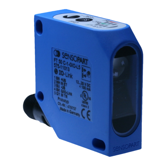
- Page 1 Montage- und Bedienungsanleitung Mounting and operating instructions FT 50 C...GIO Farbsensor mit IO-Link-Schnittstelle Colour sensor with interface IO-Link...
- Page 2 écrite de SensoPart Industriesensorik GmbH. Nous déclinons toute responsabilité concernent les fautes éventuelles d’impression et autres erreurs qui auraient pu intervenir lors du montage de cette brochure.
- Page 3 Kurzanleitung / Quick Guide / Manuel abrégé Hinweise zur Bedienung: Drücken der Tasten nur mit Finger! Keine spitzen Gegenstände verwenden! Instructions for use: Push buttons only with finger! Do not use sharp objects! Indications pour l’utilisation : N’ appuyer sur les boutons qu’avec les doigts ! Ne pas utiliser d’objets pointus ! Taste drücken Taste loslassen Farbe einlernen...
- Page 4 Maßzeichnung / Dimensional drawing / Plan coté Abb. 1 / Illustr. 1 / Fig. 1 15300350 Anschluss / Wiring / Raccordement IN ET Q/IO-Link IN TR Abb. 2 / Illustr. 2 / Fig. 2 15400487...
-
Page 5: Table Of Contents
Montage- und Bedienungsanleitung Inhaltsverzeichnis Inhaltsverzeichnis ...............................5 Symbolerklärung ..............................6 Sicherheitshinweise ..............................6 Bestimmungsgemäße Verwendung ........................7 Leistungsmerkmale...............................7 Montage ................................8 5.1 Maßzeichnung .............................8 5.2 Sensormontage ............................8 Elektrische Installation ............................9 Bedienung und Einstellung ...........................9 7.1 Anzeigen und Einstellelemente ........................10 7.2 Mögliche Einstellungen und Betriebsarten....................11 7.3 Einstellungen über das Bedienfeld vornehmen ..................12 7.3.1 Kurzanleitung siehe Ausklappseite ....................12 7.3.2 Einstellmodus aktivieren ........................12... -
Page 6: Symbolerklärung
Montage- und Bedienungsanleitung Symbolerklärung Warnhinweise und sonstige Hinweise sind in dieser Anleitung durch Symbole gekennzeichnet. Sie werden durch Signalworte eingeleitet. Die verwendeten Symbole sind: WARNUNG ... weist auf eine möglicherweise gefährliche Situation hin, die zum Tod oder zu schweren Verletzungen führen kann, wenn sie nicht gemieden wird. -
Page 7: Bestimmungsgemäße Verwendung
Montage- und Bedienungsanleitung Bestimmungsgemäße Verwendung Der FT 50 C...GIO ist ein Farbsensor zum Erkennen farblich unterschiedlicher Objekte im Tasterbetrieb (bei opaken Objekten) und Reflektorbetrieb (bei transparenten Objekten). WARNUNG Das Produkt ist für das Sichern von Personen nicht zugelassen (kein Sicherheitsbauteil gemäß Maschinenrichtlinie). -
Page 8: Montage
Montage- und Bedienungsanleitung Montage Maßzeichnung Abb. 4 15300065 Abb. 3 15300350 Sensormontage Sensor mit Befestigungsbohrungen an geeigneten Halter z.B. Typ MS F 50 oder MSP F 50* (nicht im Lieferumfang enthalten) schrauben. Sensor so positionieren, dass der Abstand vom Sensor zum Objekt möglichst konstant ist. HINWEIS Einsatzbedingungen beachten •... -
Page 9: Elektrische Installation
Montage- und Bedienungsanleitung Elektrische Installation Gerätestecker so verdrehen (Abb. 3), dass das Anschlusskabel frei und ohne abzuknicken angeschlossen werden kann. Buchse des Anschlusskabels aufstecken und verschrauben (zulässige Anzugsdrehmomente ca. 0,5 ...1 Nm). Anschlusskabel sichern (zum Beispiel mit Kabelbinder). Sensor gemäss Abb. 9 anschließen. IN ET Q/IO-Link Abb. -
Page 10: Anzeigen Und Einstellelemente
Montage- und Bedienungsanleitung Anzeigen und Einstellelemente Die Tasten und ihre Funktion: Generelle Bedienfunktionen Tasten Bezeichnung Im Betriebsmodus Im Einstellmodus Kurzes Drücken und wieder Loslassen Taste > 3 s drücken aktiviert den Einstell- bewirkt: modus Sprung in das nächste Menü ... -
Page 11: Mögliche Einstellungen Und Betriebsarten
Montage- und Bedienungsanleitung Anzeigefunktion Farbe Verwendung Im Betriebsmodus Im Einstellmodus Grün F = Functions Keine Funktion BLINKT, blinkend (Sonderfunktionen) wenn Menü „F” (Sonderfunktionen) gewählt Tol. C Grün Tol. C Keine Funktion Farbtoleranz einstellen (Tolerance Col.) (in 4 Stufen einstellbar) Tol. I Tol. -
Page 12: Einstellungen Über Das Bedienfeld Vornehmen
Montage- und Bedienungsanleitung Einstellungen über das Bedienfeld vornehmen 7.3.1 Kurzanleitung siehe Ausklappseite 7.3.2 Einstellmodus aktivieren HINWEIS = LED EIN / = LED blinkt / = LED AUS Aktivität Es folgt Bild Bemerkung LED blinkt, wenn Einstellmodus aktiviert ist. > 3 s Nach Aktivieren des Einstellmodus wird ein weiteres Zeitfenster von drücken, bis LED ca. -
Page 13: Menü „C+": Weitere Farben Einlernen, Hinzufügen, Verknüpfen
Montage- und Bedienungsanleitung Schritt Menüpunkt Aktivität Es folgt Bild Bemerkung mehrfach Farbtoleranz (Farbselektivität) auswählen drücken, bis gewünschte Toleranz gewählt ist 1 = kleinste Toleranz, 4 = größte Toleranz 3 = Werkseinstellung Farbtoleranz ist übernommen. Sensor ist bereit für die Einstellung der Intensitätstoleranz. bestätigen LED „C”... - Page 14 Montage- und Bedienungsanleitung Ablauf: Schritt Menüpunkt Aktivität Es folgt Bild Bemerkung Betriebsmo- Objekt Betriebsparameter wie Tastweite, Bewegungsrichtung, dus (kein positionieren Neigungswinkel, etc. (siehe Kapitel 5 „Montage”) beachten. Menüpunkt) LED „C” (gelb) blinkt, wenn Zeitschloss geöffnet und Ein- stellmodus aktiviert ist. >...
-
Page 15: Menü „S": Scannen Eines Einzelnen Farbbereiches
Montage- und Bedienungsanleitung * wenn Schaltart = Schließer (N.O.) = Werkseinstellung eingestellt. Zum Einlernen (Hinzufügen) weiterer Farben den Einstellablauf (Schritte 1-8) wiederholen. 7.3.5 Menü „S”: Scannen eines einzelnen Farbbereiches HINWEIS • Funktion für das Einscannen einer inhomogenen Farboberfläche. • Wird eine Farbe eingescannt, werden alle vorher eingelernten und eingescannten Farben / Farbbereiche gelöscht. -
Page 16: Menü „F": Sonderfunktionen Einstellen
Montage- und Bedienungsanleitung Ablauf: Schritt Menüpunkt Aktivität Es folgt Bild Bemerkung Betriebsmo- Objekt Betriebsparameter wie Tastweite, Bewegungsrichtung, dus (kein positionieren Neigungswinkel, etc. (siehe Kapitel 5 „Montage”) beachten. Menüpunkt) LED „C” (gelb) blinkt, wenn Zeitschloss geöffnet und Einstellmodus aktiviert ist. > 3 s drücken bis LED „C”... - Page 17 Montage- und Bedienungsanleitung Schritt Menüpunkt Aktivität Es folgt Bild Bemerkung In Werks- LEDs „Tol. I” (rot) Wurde einstellung blinken. gedrückt, blinkt zur zurück- Sensor auf Bestätigung die setzen Werkseinstellung LED „+/F” (grün) im zurücksetzen. Wechsel mit den LEDs „Tol. I” (rot). Weiter zur nächsten Funktion (Abfallverzögerung) drücken Abfallver-...
-
Page 18: Kommunikation Über Die Io-Link-Schnittstelle
Montage- und Bedienungsanleitung Kommunikation über die IO-Link-Schnittstelle IO-Link ist eine intelligente Punkt-zu-Punkt-Verbindung, signal- und anschlusskompatibel zur binären Standard- Schnittstelle. Alle FT 50 C...GIO sind mit dieser Schnittstelle ausgestattet. Es können Farbwerte übertragen oder Sensorfunktionen eingestellt werden. Damit ergeben sich folgende Nutzungsmöglichkeiten: •... -
Page 19: Prozessdaten
Montage- und Bedienungsanleitung Prozessdaten Funktion Zugriffsart Adresse Datenformat Belegung der Bits Wertebereich Prozessdaten IntegerT (8) Bit 0 entsprechen Ausgangssignal im SIO-Mode Bit 1 1 = Farbe 1 erkannt Bit 2 1 = Farbe 2 erkannt Bit 3 1 = Farbe 3 erkannt Bit 4 1 = Farbe 4 erkannt Bit 5... -
Page 20: Übersicht Der Parameter (Nach Datenkanälen Sortiert)
Montage- und Bedienungsanleitung Übersicht der Parameter (nach Datenkanälen sortiert) Parameterdaten Adresse Objektname Zugriffs- Wert Wertebereich Bemerkung art * Write: Master Befehl Kommandoschnittstelle 5Ah - Initiiere Fallback zur Einstellung der Kom- 97h - Neustart munikationsparameter 99h - Neustart, Sperrung der Prozessdaten Read: ohne Funktion A0h-FFh reserviert für herstellerspezi-... - Page 21 Funktion Zugriffs- Index Daten- Belegung Wertebereich Bemerkung art * format der Bits dez. hex. Identifikationsdaten Vendor Name StringT Sensopart Industriesensorik GmbH Vendor Text StringT www.sensopart.de Product Name R StringT FT 50 C-1-GIO-L5 Product-ID StringT 57511013 Hardware StringT 2 Byte Revision...
-
Page 22: Integration In Das Engineering System
Die Parametrierung der FT 50 C...GIO erfolgt im Engineering System mittels IODD-Dateien (IO-Link Device Descrip- tion). Die zum Farbsensor FT 50 C...GIO passenden IODD-Dateien sind im Internet als Download verfügbar unter: www.sensopart.com FT 50 C...GIO Farbsensor - D - 068-14236 - 06.10.2011-04... -
Page 23: Pflege Und Wartung
Über die IO-Link-Schnittstelle wurde per Tastenverriegelung wieder aufheben. Befehl die Tastenverriegelung aktiviert. Bei davon abweichenden Störungen wenden Sie sich bitte an Ihren Sensopart-Ansprechpartner in den für Sie zu- ständigen Vertretungen und Geschäftsstellen. FT 50 C...GIO Farbsensor - D - 068-14236 - 06.10.2011-04... -
Page 24: Technische Daten
Montage- und Bedienungsanleitung Technische Daten Optische Daten (typ.) FT 50 C-1-GIO-L5 FT 50 C-2-GIO-L5 FT 50 C-3-GIO-L5 Tastweite (ab Referenzpunkt) 12 ... 32 mm 15 ... 30 mm 18 ... 22 mm Tastweitentoleranz ± 6 mm (bei Tol C 3 ±... -
Page 25: Bestellinformationen
Haltewinkel F 50 (Sensorschutz / sehr robust) 904-51633 RF 10 C Reflexfolie 100 x 100 mm nicht im Lieferumfang enthalten HINWEIS Datenblätter, und Bedienungsanleitungen stehen unter www.sensopart.com zum Herunterladen bereit. FT 50 C...GIO Farbsensor - D - 068-14236 - 06.10.2011-04... -
Page 26: Contents
Mounting and operating instructions Contents Contents ...................................26 Guide to symbols ..............................27 Safety instructions ..............................27 Correct use .................................28 Performance ...............................28 Mounting ................................29 5.1 Dimensional drawing ..........................29 5.2 Mounting the sensor ..........................29 Electrical installation ............................30 Use and configuration ............................30 7.1 Displays and configuration elements ......................31 7.2 Possible configurations and operating modes ...................32 7.3 Configuration via the control panel ......................32 7.3.1 Quick user guide: see fold-out page ....................32... -
Page 27: Guide To Symbols
Mounting and operating instructions Guide to symbols Warnings and other information are signalled by symbols in this manual. They are accompanied by hea- dings. The following symbols are used: WARNING ... indicates a possibly dangerous situation which can cause death or serious injury if not avoided. CAUTION ... -
Page 28: Correct Use
Mounting and operating instructions Correct use The FT 50 C...GIO is a colour sensor for the detection of objects in varying colours in proximity mode (for opaque objects) and reflector mode (for transparent objects). WARNING The product is not approved for the protection of personnel (no safety component according to Machinery Directive). -
Page 29: Mounting
Mounting and operating instructions Mounting Dimensional drawing Illustr. 5 15300065 Illustr. 4 15300350 Mounting the sensor Screw sensor to suitable holder, e.g. type MS F 50 or MSP F 50* (not included in delivery) using the fixing holes. Fit the sensor in a place where the distance to the object is as constant as possible (little variation in scanning distance). -
Page 30: Electrical Installation
Mounting and operating instructions Electrical installation Rotate the connector plug (illustr. 3) so that the cable can be connected easily, without kinks. Fit socket of the connector cable and screw tight (authorised approx. tightening torque 0.5 to 1 Nm). Secure connection cable (for example with cable retainer). Connect sensor according to illustr. -
Page 31: Displays And Configuration Elements
Mounting and operating instructions Displays and configuration elements Keys and their functions: General operating functions Keys Description In operating mode In configuration mode Pressing key > 3 s activates configuration Quick press and release: mode jump to next menu ... -
Page 32: Possible Configurations And Operating Modes
Mounting and operating instructions Display function Colour In operating mode In configuration mode Tol. C Green Tol. C No function Set colour tolerance (4 levels). (Tolerance Col.) Tol. I Tol. I No function Set intensity (grey levels) (Tolerance Int.) (4 levels). Tol. -
Page 33: Activate Configuration Mode (Conf)
Mounting and operating instructions 7.3.2 Activate configuration mode (conf) INFORMATION = LED ON / = LED flashes / = LED OFF Activity Picture follows Remark LED flashes when configuration mode is activated. > 3 s Once configuration mode has been activated, a time window of approx. until LED „C”... -
Page 34: Menu „C+": Teach, Add, Link Further Colours
Mounting and operating instructions Step Menu item Activity Picture follows Remark Confirm with Colour tolerance is stored. Sensor is ready for the setting of intensity tolerance. LED „C” (yellow) lights up when colour is detected,* LEDs „Tol.I” (red) light up. Press Select intensity tolerance (grey selectivity). - Page 35 Mounting and operating instructions Step Menu item Activity Picture follows Remark Press Menu „Scan further colours” is selected LED „C” and „+” (yellow) flashes. Teach Press Press button briefly and release it. When the button gets colours released, the colour is taught. Release Colour value is stored in sensor.
-
Page 36: Menu „S": Scan A Single Colour Range
Mounting and operating instructions 7.3.5 Menu „S”: Scan a single colour range INFORMATION • Function for the scanning of an inhomogeneous colour surface. • If a colour is scanned, all previously taught and scanned colours / colour ranges are deleted. •... -
Page 37: Menu „F": Configurating Special Functions
Mounting and operating instructions Procedure: Step Menu item Activity Picture follows Remark Operating Position object Observe operating parameters such as scanning distance, mode (no direction of movement, inclination etc. (see chapter 5 menu item) „Mounting”). Press LED „C” (yellow) flashes, when time lock is open and configuration mode is activated. -
Page 38: Communication Via The Io-Link Interface
Mounting and operating instructions Step Menu item Activity Picture follows Remark Reset to LEDs „Tol. I” (red) factory flash. pressed, the LED setting Reset sensor to „S+/F” (green) factory setting with flashes alternately with LEDs „Tol. I” (red) to confirm. Press Continue to next function (OFF delay time). -
Page 39: Basic Characteristics Of The Io-Link Interface
Mounting and operating instructions Basic characteristics of the IO-Link interface When operating voltage is switched on, the sensor is in I/O mode (SIO mode). It is set to the communication mode (COM-Mode) by „Wake up”. It is possible to cyclically transfer process data and to noncyclically receive and send parameter data / service data. The physical features of the sensor‘s IO-Link interface are: Physics: COM 2 (38.4 kBaud) -
Page 40: Overview Of Parameters (Sorted By Data Channels)
Mounting and operating instructions Overview of parameters (sorted by data channels) Parameter data Address Object name Access Value Range Remark mode * Write: Master Command R/W Command interface for 5Ah - initate fallback control of communication 97h - goto start-up state state machine 99h - goto operate state, PD out invalid... - Page 41 Function Access Index Data Bit assign- Range Remark mode * format ment dez. hex. Identification data Vendor Name StringT SensoPart Industriesensorik GmbH Vendor Text StringT www.sensopart.com Product Name R StringT FT 50 C-1-GIO-L5 Product-ID StringT 57511013 Hardware StringT 2 byte...
-
Page 42: Integration In The Engineering System
Parameterization of FT 50 C...GIO is made in the Engineering System by means of IODD file (IO-Link Device De- scription). The IODD files suitable for colour sensors FT 50 C...GIO are available for download in the internet at: www.sensopart.com FT 50 C...GIO Colour sensor - GB - 068-14236 - 06.10.2011-04... -
Page 43: Care And Maintenance
Mounting and operating instructions Care and maintenance Cleaning Should the front screen of the sensor become dirty, wipe it with a soft cloth and if necessary use a cleaning agent for plastic surfaces. CAUTION Never use aggressive detergents. Transport, packaging, storage Check the delivery upon receipt to ensure that it is complete and that no damage occurred during transport. -
Page 44: Technical Data
Mounting and operating instructions Technical data Optical data (typ.) FT 50 C-1-GIO-L5 FT 50 C-2-GIO-L5 FT 50 C-3-GIO-L5 Scanning distance (from reference point) 12 ... 32 mm 15 ... 30 mm 18 ... 22 mm Scanning distance tolerance ± 6 mm (with Tol C 3 ±... -
Page 45: Order Information
Mounting bracket F 50 (sensor protection / very robust) 904-51633 RF 10C Reflex foil 100 x 100 mm Accessories (not included in delivery) INFORMATION Data sheets and instruction manuals are available for download on www.sensopart.com. FT 50 C...GIO Colour sensor - GB - 068-14236 - 06.10.2011-04... - Page 48 Kontaktadressen / Contact addresses / Contacts Deutschland France SensoPart Industriesensorik GmbH SensoPart France SARL Nägelseestraße 16 11, rue Albert Einstein D-79288 Gottenheim Espace Mercure Tel.: +49 (0) 7665 - 94769 - 0 F-77420 Champs sur Marne Fax: +49 (0) 7665 - 94769 - 765 Tél.: +33 (0) 1 64 73 00 61...
Need help?
Do you have a question about the FT 50 C-2-GIO-L5 and is the answer not in the manual?
Questions and answers