Table of Contents
Advertisement
Quick Links
Advertisement
Table of Contents

Subscribe to Our Youtube Channel
Related Manuals for Stryker 1550


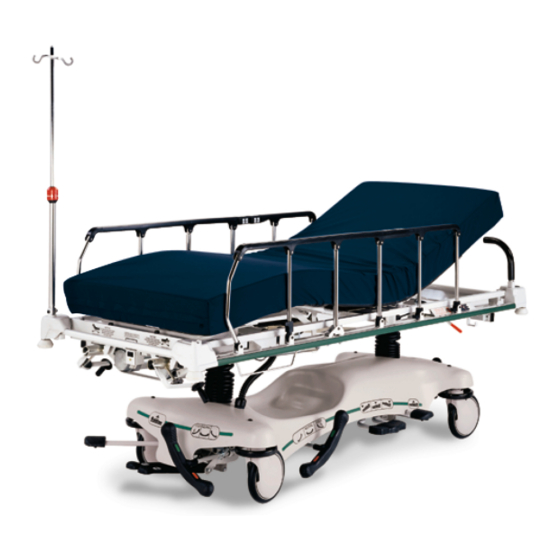
Summary of Contents for Stryker 1550
- Page 1 O p e r a t i o n s Me d i c a l Ma n u a l E l e c t r i cS t r e t c h e r Mo d e l 1 5 5 0 I mp o r t a n t I n f o r ma t i o n F i l e i n y o u r...
-
Page 3: Table Of Contents
Table of Contents Introduction Specifications ................Warning / Caution / Note Definition . -
Page 4: Introduction
Introduction INTRODUCTION This manual is designed to assist you with the operation of the model 1550 Electric Stretcher. Read it thor- oughly before using the equipment. SPECIFICATIONS Safe Working Load 500 pounds (227 kilograms) Overall Bed Length/Width 83.5”/34” Minimum/Maximum Bed Height 22”/35”... -
Page 5: Stretcher Symbols
Stretcher Symbols Warning, Rever to Operations or Service/Maintenance Manual Safe Working Load Symbol Medical Equipment Listed by Underwriters Laboratories Inc. with Respect to Electric Shock, Fire and Accidental Hazards Only in Accordance with UL 544. UL60601−1 CAN/CSA C22.2 NO.601.1 Return to Table of Contents... -
Page 6: Operating Base Controls
Stretcher Operation OPERATING BASE CONTROLS − UNI−LOWER PEDAL Pump to raise litter. Depress in the center of pedal (B) to lower both ends of the stretcher together. Depress the side of pedal (B) closest to the foot end of the stretcher to lower the foot end. Depress the side of pedal (B) closest to the head end of the stretcher to lower the head end. - Page 7 Stretcher Operation OPERATING BASE CONTROLS − DUAL LOWERING PEDALS Pump to raise litter. Depress to lower head end. Depress to lower foot end. Note: Depress B & C together to lower both ends of the litter simultaneously. Brake and Steer functions (foot end). Brake and Steer functions (head end).
-
Page 8: Raising And Lowering Litter Height
Stretcher Operation RAISING AND LOWERING LITTER HEIGHT − UNI−LOWER PEDAL CAUTION Be sure to move any equipment that may be in the way before raising or lowering the litter height. To raise the litter height, pump pedal (A) repeatedly until the desired height is achieved (see illustration on page To lower both ends of the litter together, depress the center of pedal (B). -
Page 9: Trendelenburg/Reverse Trendelenburg Positioning
Stretcher Operation TRENDELENBURG/REVERSE TRENDELENBURG − UNI−LOWER PEDAL NOTE Litter height must be raised first in order to achieve a trend. or reverse trend. position. CAUTION Be sure to remove any equipment that may be in the way before lowering stretcher. For Trendelenburg positioning (head down), depress the side of pedal (B) closest to the head end of the stretcher (see illustration, page... -
Page 10: Applying The Brake System
Stretcher Operation APPLYING THE BRAKE SYSTEM NOTE For user convenience, the brake/steer pedal is located on both ends of the stretcher. WARNING Always apply the caster brakes when a patient is getting on or off the stretcher. Push on the stretcher to en- sure the brakes are securely locked. -
Page 11: Operating Fowler And Knee Gatch
Stretcher Operation OPERATING FOWLER AND KNEE GATCH CRANKS WARNING To avoid accidental activation and injury while using the cranks, lock out the patient controls (using the switch at either end of the bed) or unplug the stretcher power cord from the wall receptacle. (A) Push in crank and rotate until it engages. -
Page 12: Operating Siderails
Stretcher Operation OPERATING SIDERAILS CAUTION Be sure the siderail latching mechanism (A) is working properly at all times. If it is not, refer to your stretcher maintenance manual for ”Siderail Latch Adjustment”. To engage siderails: Pull up siderail (B) and raise to full up position so that latch (A) engages. To disengage siderails: Pull up on latch (A) and guide siderail to the full down position. -
Page 13: Operating Siderail Patient Controls
Stretcher Operation OPERATING SIDERAIL PATIENT CONTROLS Each siderail has a set of controls to allow the patient to position the Fowler and Knee Gatch. The power cord must be plugged into the wall socket for the patient controls to operate. FOWLER UP FOWLER DOWN GATCH UP... -
Page 14: Using Push Handles
Stretcher Operation USING PUSH HANDLES CAUTION The push handles at the head end of the stretcher should always be used when transporting patients. They were installed for this purpose for user convenience. Using other parts of the stretcher as push devices could cause damage. -
Page 15: Operating Optional Permanently Attached I.v. Poles
Stretcher Operation OPERATING OPTIONAL 2−STAGE PERMANENTLY ATTACHED IV POLE DETAIL OF IV POLE LATCH NOTE The 2−stage permanently attached IV pole is an option and may have been installed at either the head, foot or both ends of the stretcher. The choice was made at the time the stretcher was purchased. To use the 2−stage permanently attached IV pole: 1. - Page 16 Stretcher Operation OPERATING OPTIONAL 3−STAGE PERMANENTLY ATTACHED IV POLE DETAIL OF IV POLE LATCH DETAIL OF IV POLE GRIP NOTE The 3−stage permanently attached IV pole is an option and may have been installed at either the head, foot or both ends of the stretcher. The choice was made at the time the stretcher was purchased. To use the 3−stage permanently attached IV pole: 1.
-
Page 17: Operating Optional Foot Extension/Defibrillator Tray
Stretcher Operation OPERATING THE OPTIONAL FOOT EXTENSION/DEFIBRILLATOR TRAY 1. To use as a defibrillator tray, pull out the top knob (A) and pivot the tray (B) over the foot extension (C) until the tray extends flat over the foot end of the stretcher. -
Page 18: Using The Optional Serving Tray
Stretcher Operation USING THE OPTIONAL SERVING TRAY FOOT Pull out on either end of the serving tray to extend it to the proper width to fit on top of the stretcher siderails. To store the serving tray in the optional serving tray holder/foot board, push in both ends of the serving tray and slide it into the holder. -
Page 19: Using The Optional Upright Oxygen Bottle Holder
Stretcher Operation USING THE OPTIONAL UPRIGHT OXYGEN BOTTLE HOLDER Support Cotter Pin Insert the support bar into the IV socket at any of the four litter corners. Insert the cotter pin through the hole in the support bar to hold the bottle holder in place. CAUTION To avoid damage, do not put items weighing more than 40 pounds in the upright oxygen bottle holder. -
Page 20: Using The Optional Defibrillator Tray
Stretcher Operation USING THE OPTIONAL DEFIBRILLATOR TRAY Insert the the pins on the defibrillator tray into the footboard sockets at the foot end of the stretcher. Secure the equipment to the tray using the strap. CAUTION To avoid damage, do not put items weighing more than 30 pounds on the defibrillator tray. Return to Table of Contents... -
Page 21: Cleaning
SOME CLEANING PRODUCTS ARE CORROSIVE IN NATURE AND MAY CAUSE DAMAGE TO THE PRODUCT IF USED IMPROPERLY. If the products described above are used to clean Stryker patient care equipment, measures must be taken to insure the beds are wiped with clean water and thoroughly dried fol- lowing cleaning. -
Page 22: Preventative Maintenance Checklist
Preventative maintenance should be performed at a minimum of annually. A preventative maintenance pro- gram should be established for all Stryker Medical equipment. Preventative maintenance may need to be performed more frequently based on the usage level of the product. -
Page 23: Limited Warranty
Stryker’s obligation under this warranty is expressly limited to supplying replacement parts and labor for, or replacing, at its option, any product which is, in the sole discretion of Stryker, found to be defective. If re- quested by Stryker, products or parts for which a warranty claim is made shall be returned prepaid to Stryker’s factory. -
Page 24: Return Authorization
Stryker will perform all service during regular business hours (9−5) * Replacement parts and labor for products under PM contract will be discounted. ** Does not include any disposable items, I.V. poles (except for Stryker HD permanent poles), mattresses, or damage re- sulting from abuse. - Page 25 European Representative Stryker EMEA RA/QA Director Stryker France ZAC Satolas Green Pusignan Av. De Satolas Green 69881 MEYZIEU Cedex France 3800 E. Centre Ave., Portage, MI 49002 (800) 327−0770 www.stryker.com JH 11/06 1550−190−025 REV G...
Need help?
Do you have a question about the 1550 and is the answer not in the manual?
Questions and answers