Stryker Renaissance Series Maintenance Manual
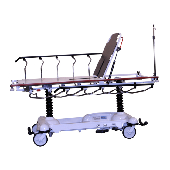
Emergency care stretcher
Hide thumbs
Also See for Renaissance Series:
- Operation manual (17 pages) ,
- Maintenance manual (196 pages)

Related Manuals for Stryker Renaissance Series


Summary of Contents for Stryker Renaissance Series
- Page 1 Renaissance Series 1212 Emergency Care Stretcher Maintenance Manual For Parts or Technical Assistance 800–327–0770...
-
Page 2: Table Of Contents
Table of Contents Introduction Specifications ............... . Warning / Caution / Note Definition . - Page 3 Table of Contents Assembly Drawings and Parts Lists (Continued) Knee Gatch Frame Assembly ............Crank Knee Gatch Assembly .
-
Page 4: Introduction
Introduction INTRODUCTION This manual is designed to assist you with the maintenance of the 1212 Emergency Care Stretcher. Read it thoroughly before using the equipment or beginning any maintenance on it. SPECIFICATIONS Maximum Weight Capacity 500 pounds Overall Bed Length \ Width 83 1/2”... -
Page 5: Preventative Maintenance
These products are corrosive in nature and may cause dam- age to your stretcher if used improperly. If these types of products are used to clean Stryker patient handling equipment, measures must be taken to insure the stretchers are rinsed with clean water and thoroughly dried following cleaning. -
Page 6: Service Information
Service Information CASTER ASSEMBLY REPLACEMENT* Required Tools: 1/8 Roll Pin Punch Drill with 1/8 inch Drill Bit Flat Punch (any size larger than 1/8) Hammer Needle Nose Pliers Floor Jack 3/4 Inch Wrench Bungee Cords 1 Inch Wrench Torque Wrench (w/ Ft. Lbs. Adjust.) Replacement Procedure: 1. -
Page 7: Caster Cover Installation And Removal
Service Information CASTER COVER INSTALLATION AND REMOVAL Looking through the larger of the two side cut–outs, align cover with axle nut or bolt head, as shown. Double Prongs Push down on the opposite side of the cover until single prong engages with caster horn. Single Prong Top View (Cut–Away) Properly Attached... -
Page 8: Pneumatic Fowler Adjustment
Service Information PNEUMATIC FOWLER ADJUSTMENT Required Tools: 5/32” Hex Allen Wrench 1/2” Open End Wrench Adjustment Procedure: 1. Refer to drawing 1210–31–120 (Pneumatic Fowler Assembly, page 49) for parts reference. 2. For easier access, move Fowler to 75 degrees or higher. 3. -
Page 9: Brake Ring Replacement
Service Information BRAKE RING REPLACEMENT Brake Ring Part Number 715–1–61 Required Tools: Phillips Screwdriver String or Bungee Cord Floor Jack, Small Crate (or equiv.) Large Standard Screwdriver 3/32” Allen Wrench 11/16” Socket & Ratchet 5/8” Wrench Needle–Nose Pliers (2) 7/16” Wrenches Procedure: 1. -
Page 10: Jack Replacement
Service Information JACK REPLACEMENT (WITHOUT COMPRESSION SPRING) Required Tools: 3/8” Wrench 1/2” Socket 1/2” Wrench Needle–Nosed Pliers Replacement Procedure: 1. Apply stretcher brakes. Raise litter to full up. Raise Fowler to full up and raise siderails. 2. Use a 3/8” wrench to remove the bolt in the litter support tube above black bellows on both ends. 3. -
Page 11: Hydraulic System Troubleshooting
Jack will not pump up and the jack actuator rod Remove excess air (vacuum) in system (see p. may or may not move. 13). Contact Stryker technical service at 1–800–327–0770 for further assistance. -
Page 12: Checking Hydraulic Fluid Level
6. The hydraulic fluid should be visible at the bottom of the fill hole. If it is not, add Mobil Aero HFA hydraulic fluid (Stryker part number 2020–70–475) until the fluid is visible at the bottom of the fill hole. Replace the fill plug. -
Page 13: Hydraulic Check Valve Replacement
Service Information HYDRAULIC CHECK VALVE REPLACEMENT Required Tools: 3/8 Open End Wrench Stiff Wire (with bent, pointed end) Small Needle Nose Pliers 3/4 Open End Wrench Torque Wrench (with Ft. Lbs. adjust.) 7/32 Hex Allen Wrench 1/2 Inch Diameter Rod Replacement of Valve #1 WARNING To avoid personal injury or damage to the stretcher, remove the litter and the base hood before beginning... -
Page 14: Replacement Of Valve (Poppet) #2
Service Information HYDRAULIC CHECK VALVE REPLACEMENT (CONTINUED) Replacement of Valve (Poppet) #2 WARNING To avoid personal injury or damage to the stretcher, remove the litter and the base hood before beginning service on the jacks. Lower the jack rod completely to relieve the pressure on the pump piston side of the jack. -
Page 15: Base Lubrication Points
Service Information BASE LUBRICATION POINTS 1. Lubricate brake adjuster rod around area shown with MPG–2 grease or equivalent. Do not grease area shown. - Page 16 3–Sided Control Base Ass’y, Both Sides & Foot End...
- Page 17 3–Sided Control Base Ass’y, Both Sides & Foot End...
- Page 18 3–Sided Control Base Ass’y, Both Sides & Foot End Item Part No. Part Name Qty. Item Part No. Part Name Qty. 3–4 Hex Hd. Cap Screw 715–1–158 Caster Nut 3–47 Hex Hd. Cap Screw 715–1–165 Actuator Plate Ass’y 3–62 Hex Hd. Cap Screw 715–1–192 Jack Support 3–85...
- Page 19 3–Sided Control Base Ass‘y, Both Sides & Head End...
- Page 20 3–Sided Control Base Ass’y, Both Sides & Head End...
- Page 21 3–Sided Control Base Ass‘y, Both Sides & Head End Item Part No. Part Name Qty. Item Part No. Part Name Qty. 3–4 Hex Hd. Cap Screw 715–1–158 Caster Nut 3–47 Hex Hd. Cap Screw 715–1–165 Actuator Plate Ass’y 3–62 Hex Hd. Cap Screw 715–1–192 Jack Support 3–85...
- Page 22 Assembly part number 1210–4–10 FOOT END...
- Page 23 FOOT END Assembly part number 1210–4–10 HEAD END...
-
Page 24: 4-Sided Control Base Assembly
4–Sided Control Base Assembly Item Part No. Part Name Qty. Item Part No. Part Name Qty. 3–4 Hex Hd. Cap Screw 715–1–158 Caster Nut 3–47 Hex Hd. Cap Screw 715–1–165 Actuator Plate Ass’y 3–62 Hex Hd. Cap Screw 715–1–192 Jack Support 3–85 Hex Hd. -
Page 25: Jack Assembly
Variable Descent Jack Assembly Assembly part number Item Part No. Part Name Qty. 1210–70–10 45–904 O–Ring 715–1–340 Cap Assembly 390–1–243 Gasket 715–1–323 Actuator Cylinder 715–1–325 Actuator 45–14 O–Ring 926–20–161 Parker Packing 715–1–331 Piston End 926–20–162 Wear Ring 4–14 Soc. Hd. Cap Screw 45–110 O–Ring 388–1–38... - Page 26 Variable Descent Jack Base Assembly Assembly part number 1210–70–11 Item Part No. Part Name Qty. Item Part No. Part Name Qty. 1210–70–12 Jack Base, Machined 715–1–328 Piston Wear Ring 1210–70–13 Base Plug 14–50 Bearing Retainer 1210–70–14 715–1–327 Cylinder Wear Ring 45–966 O–Ring 715–1–316...
-
Page 27: Jack Base Assembly
Standard Jack Assembly Assembly part number 715–270–10 Item Part No. Part Name Qty. Item Part No. Part Name Qty. 45–904 O–Ring 45–110 O–Ring 715–1–340 Cap Assembly 388–1–38 Plug 390–1–243 Gasket 715–1–322 Reservoir 715–1–323 Actuator Cylinder 390–1–244 Gasket 715–1–325 Actuator 390–1–238 Gasket, Actuator 45–14 O–Ring... - Page 28 Standard Jack Base Assembly Assembly part number 715–270–5 Item Part No. Part Name Qty. Item Part No. Part Name Qty. 1210–70–12 Jack Base 45–110 O–Ring 1210–70–13 Base Plug 715–1–328 Piston Wear Ring 715–270–1 14–50 Bearing Retainer 45–966 O–Ring 715–1–327 Cylinder Wear Ring 38–311 Compression Spring 715–1–316...
-
Page 29: Brake Adjuster Assembly
Brake Adjuster Assembly Assembly part number 715–1–150 Item Part No. Part Name Qty. 715–1–62 Threaded Stud Assembly 14–4 Nylon Washer 715–1–180 Bearing 28–8 Retaining Ring... -
Page 30: Brake Cam Assembly
Brake Cam Assembly Assembly part number 715–1–213 Item Part No. Part Name Qty. 715–1–221 Brake Cam 16–59 Fiberlock Nut 8–21 Soc. Hd. Cap Screw 715–1–173 Brake Connecting Link... - Page 31 End Control Pump Pedal Assembly, Head Assembly part number 716–1–292 Item Part No. Part Name Qty. 716–1–285 Pump Pivot, Head End 26–12 Roll Pin 716–1–290 Pump Ped. Wldmt., Head 721–40–25 Pedal End Control Pump Pedal Assembly, Foot Assembly part number 716–1–288 Item Part.No.
-
Page 32: Side Release Pedal Assembly, Right
Side Release Pedal Assembly, Right Assembly part number 1210–1–50 Item Part No. Part Name Qty. 1210–1–51 Side Release Weldment, Rt. 715–1–126 Side Control Pedal Pad Side Release Pedal Assembly, Left Assembly part number 1210–1–52 Item Part No. Part Name Qty. 1210–1–53 Side Release Weldment, Lt. -
Page 33: Side Pump Pedal Assembly
Side Pump Pedal Assembly Assembly part number 715–1–108 Item Part No. Part Name Qty. 715–1–83 Pedal Ass’y Weldm’t, Pump 715–1–126 Side Control Pedal Pad 81–44 Bearing, Bronze NOTE Apply plastic adhesive to the mating surfaces of item B prior to assembly. -
Page 34: Caster Assembly With Steerlock
Caster Assembly with Steerlock Assembly part number 715–2–21 Item Part No. Part Name Qty. 700–10–50 Steer Lock Caster Weldment 715–2–25 Caster Wheel 16–60 Hex Nut 3–99 Hex Bolt 715–3–96 Hex Bolt 1000–59–10 Latch Assembly 11–310 Flat Washer... -
Page 35: Caster And Caster Cover Replacement Kits
Caster and Caster Cover Replacement Kits Item Part No. Part Name Qty. 715–2–20 Caster Assembly 715–1–266 Caster Cover, Left 715–1–265 Caster Cover, Right P/N 715–259–400 – Kit to replace 4 standard caster assemblies with necessary hardware – no caster covers. P/N 715–269–400 –... -
Page 36: Fifth Wheel Assembly
Fifth Wheel Assembly Assembly part number 715–1–25 Item Part No. Part Name Qty. 715–1–339 Fifth Wheel Pivot Assembly 715–1–17 Fifth Wheel Bushing 16–11 Flexlock Nut 715–1–15 Spring 715–1–13 Fifth Wheel Bracket 16–12 Flexlock Nut 390–1–54 Wheel 3–31 Hex Head Cap Screw 3–82 Hex Head Cap Screw... -
Page 37: 3-Sided Base Graphics, Foot End Control
3–Sided Base Graphics, Foot End Control Assembly part numbers 1210–750–10 thru 1210–750–70 Item Part No. Part Name Qty. 1210–750–9 Head End Brake/Steer Label 1210–800–9 Renaissance Series Label 1210–45–25 Base Hood 946–1–60 Stryker Logo Label 715–1–134 Bellows 1212–1–17 Specification Label Color... -
Page 38: 3-Sided Base Graphics, Head End Control
3–Sided Base Graphics, Head End Control Assembly part numbers 1210–800–10 thru 1210–800–70 Item Part No. Part Name Qty. 1210–800–9 Renaissance Series Label 1210–750–8 Foot End Brake/Steer Label 1210–45–25 Base Hood 946–1–60 Stryker Logo Label 715–1–134 Bellows 1212–1–17 Specification Label Color... -
Page 39: 4-Sided Base Graphics
4–Sided Base Graphics Assembly part numbers 1210–850–10 thru 1210–850–70 Item Part No. Part Name Qty. 1210–800–9 Renaissance Series Label 1210–45–25 Base Hood 715–1–134 Bellows 1212–1–17 Specification Label Color Item A Control Item C Control Item D Control Item E Control... -
Page 40: Litter Assembly, Fold To Head Siderails
Litter Assembly, Fold to Head Siderails Assembly part number 1001–30–10 Item Part No. Part Name Qty. Item Part No. Part Name Qty. 3–76 Hex Hd. Cap Screw 938–1–401 Collar 3–78 Hex Hd. Cap Screw 1001–1–36 Hole Plug 4–181 But. Hd. Cap Screw 1001–1–37 Jack Supt. -
Page 41: Siderail To Litter Assembly, Fold To Head
Siderail to Litter Assembly, Fold to Head Assembly part number 1211–20–10 Item Part No. Part Name Qty. Item Part No. Part Name Qty. 3–78 Hex Hd. Cap Screw 16–36 Nylock Nut 4–161 But. Hd. Cap Screw 37–200 Vinyl Sleeve 4–169 But. -
Page 42: Glideawayt Siderail Assembly, Right
Glideaway Siderail Assembly, Right Assembly part number 1001–26–10 Item Part No. Part Name Qty. 1001–26–40 Top Rail, Right 1001–226–41 Upright, Plated, Right (page 40.1) Ring Spacer Assembly 1010–26–82 Sleeve Bearing 721–26–69 Upright Sleeve 123–20–52 Spindle Plug 25–114 Semi–Tubular Rivet 1001–226–31 Lock Upright Ass’y, Rt. -
Page 43: Glideawayt Siderail Assembly, Left
Glideaway Siderail Assembly, Left Assembly part number 1001–26–11 Item Part No. Part Name Qty. 1001–26–30 Top Rail, Left 1001–226–42 Upright, Plated, Left (page 40.1) Ring Spacer Assembly 1010–26–82 Sleeve Bearing 721–26–69 Upright Sleeve 123–20–52 Spindle Plug 25–114 Semi–Tubular Rivet 1001–226–33 Lock Upright Ass’y, Left 1001–226–38 Upright Assembly, Left... - Page 44 Siderail Ring Spacer Assembly Assembly part number 1001–26–39 Item Part No. Part Name Qty. 4–169 Socket Button Hd. Cap Screw 16–3 Hex Nut 1001–26–32 Ring Spacer 40.1...
- Page 45 Notes 40.2...
-
Page 46: Head End Siderail Latch Option Assembly
Head End Siderail Latch Option Assembly Assembly part number 1001–27–10 Item Part No. Part Name Qty. 1001–27–17 Handle Bracket, Left 1001–27–18 Handle Bracket, Right 1001–27–15 Handle Weldment 1001–27–24 Link, Left 25–79 Pop Rivet 1001–27–19 Link Channel 1001–27–23 Link, Right 11–16 Flat Washer 27–8 Cotter Pin... -
Page 47: Push Handle Option Assembly
Push Handle Option Assembly Assembly part numbers 1212–151 (Foot) & 1212–152 (Head) HEAD END HANDLES P/N 1212–152 FOOT END HANDLES P/N 1212–151 Item Part No. Part Name Qty. 4–135 But. Hd. Cap Screw 4–182 But. Hd. Cap Screw 16–28 Fiberlock Nut 16–35 Nylock Hex Nut 22–10... -
Page 48: Push Handle Assembly
Push Handle Assembly Assembly part number 1211–151–10 Item Part Name Part No. Qty. 26–10 Roll Pin 1010–254–24 Stop Link 1211–151–18 Sleeve Assembly... -
Page 49: Stationary Foot End Assembly
Stationary Foot End Assembly (Fiberresin) Assembly part number 1010–332–20 Frame Assembly (Ref.) Item Part No. Part Name Qty. 1010–332–21 Footsection Skin, Fiberresin 7900–1–102 Velcro Pile 24 1/2” 25–50 Pop Rivet... -
Page 50: Knee Gatch Frame Assembly
Knee Gatch Frame Assembly Assembly part number 1010–434–20 Item Part No. Part Name Qty. Item Part No. Part Name Qty. 3–47 Hex Hd. Cap Screw 721–31–65 Litter Hole Plug (not shown) 2 3–76 Hex Hd. Cap Screw 946–1–65 Label, Gatch Symbol 4–105 Soc. -
Page 51: Crank Knee Gatch Assembly
Crank Knee Gatch Assembly (Fiberresin) Assembly part number 1010–534–10 Frame Assembly (Ref.) Item Part No. Part Name Qty. (page 45) Knee Gatch Assembly 1010–334–27 Midsection Skin 1010–334–28 Thigh Skin 1010–334–126 Calf Skin 25–50 Pop Rivet... -
Page 52: Knee Gatch Crankscrew Assembly
Knee Gatch Crankscrew Assembly Assembly part number 1001–34–19 Item Part No. Part Name Qty. 946–33–18 Crank Disk 1550–1–16 Crank Assembly 26–45 Roll Pin 26–14 Roll Pin 81–176 Thrust Washer 81–175 Thrust Bearing 81–174 Thrust Washer 938–1–175 Bearing Assembly 938–1–177 Knob 378–24–29 Shoulder Bolt 16–5... -
Page 53: Pneumatic Fowler To Frame Assembly
Pneumatic Fowler to Frame Assembly Assembly part number 1210–31–10 Item Part No. Part Name Qty. 4–182 But. Hd. Cap Screw 4–183 But. Hd. Cap Screw 11–179 Nylon Washer 14–21 Nylon Washer 16–11 Nylock Hex Nut 16–35 Nylock Hex Nut 23–100 Self–Tapping Screw 25–50 Pop Rivet... -
Page 54: Pneumatic Fowler Assembly
Pneumatic Fowler Assembly (Fiberresin) Assembly part number 1210–31–120 Item Part No. Part Name Qty. 4–161 Hex Soc. But. Hd. Cap Screw 7–20 Truss Hd. Mach. Screw 25–124 Pop Rivet 15–37 Jam Nut 15–50 Hex Nut 16–28 Nylock Nut 21–125 Set Screw 21–126 Set Screw 1001–1–36... - Page 55 Outer Housing Assembly, Right and Left Assembly part number 1210–31–106 (Right) Item Part No. Part Name Qty. 25–144 Semi–Tubular Rivet 1210–31–103 Pivot Tab 1210–31–104 Outer Housing, Right Assembly part number 1210–31–107 (Left) Item Part No. Part Name Qty. 25–144 Semi–Tubular Rivet 1210–31–103 Pivot Tab 1210–31–105...
- Page 56 Notes 49.2...
-
Page 57: Crank Fowler Assembly
Crank Fowler Assembly (Fiberresin) Assembly part number 1210–33–10 Item Part No. Part Name Qty. Item Part No. Part Name Qty. 4–97 Hex But. Hd. Cap Screw 25–50 Pop Rivet 4–183 But. Hd. Cap Screw 946–1–64 Fowler Operation Label 7–20 Truss Hd. Mach. Screw 1001–1–36 Hole Plug 8–15... -
Page 58: Fowler Crankscrew Assembly
Fowler Crankscrew Assembly Assembly part number 1001–33–25 Item Part No. Part Name Qty. 1001–33–26 Drive Bar Assembly 1550–1–16 Crank Assembly 946–33–18 Crank Disc 938–1–177 Knob 16–5 Kep Nut 378–24–29 Shoulder Bolt 946–33–35 Fowler Screw 26–14 Roll Pin 81–174 Thrust Washer 938–1–175 Bearing Assembly 81–176... -
Page 59: Head End Push Bar Assembly
Head End Push Bar Assembly Assembly part number 1001–155 Item Part No. Part Name Qty. 3–78 Hex Hd. Cap Screw 16–28 Fiberlock Nut 26–12 Roll Pin 1001–155–10 Push Bar Weldment 1001–155–14 Push Bar Socket Weldment... -
Page 60: 2-Stage I.v. Mounting Assembly
2–Stage I.V. Mounting Assembly Assembly part number 1001–81 & 1001–82 FOOT END, RIGHT HEAD END, LEFT Item Part No. Part Name Qty. (page 54) I.V. Pole Assembly 1001–59–12 I.V. Clip 1001–259–17 Socket Ass’y, Left 4–91 But. Hd. Cap Screw 16–28 Nylock Hex Nut 4–161 Button Hd. -
Page 61: 2-Stage I.v. Pole Assembly
2–Stage I.V. Pole Assembly Assembly part number 1211–110–10 RING ORIENTATION Item Part No. Part Name Qty. 1001–59–32 Base Tube Assembly 1001–59–31 Extension Tube Assembly 1210–110–47 Lock Ring 1210–110–49 Lock Actuator 14–20 Nylon Flat Washer As Req’d 1010–59–16 I.V. Hook 52–17 Nylon Spacer 926–400–62 Stop Sleeve... -
Page 62: 3-Stage I.v. Mounting Assembly
3–Stage I.V. Mounting Assembly Assembly part numbers 1001–61 & 1001–62 FOOT END HEAD END Item Part No. Part Name Qty. (page 56) I.V. Pole Assembly 1001–59–12 I.V. Clip 1001–259–17 Socket Assembly 4–91 But. Hd. Cap Screw 16–28 Nylock Hex Nut 4–161 Button Hd. -
Page 63: 3-Stage I.v. Pole Assembly
3–Stage I.V. Pole Assembly Assembly part number 1001–61–10 Item Part No. Part Name Qty. 1001–61–34 Base Tube Assembly (page 57) 2nd Stage Assembly (page 58) 3rd Stage Assembly 26–6 Roll Pin 7–4 Truss Hd. Mach. Screw 52–17 Nylon Spacer 1010–59–16 I.V. -
Page 64: 2Nd Stage Assembly
2nd Stage Assembly Assembly part number 721–61–25 Item Part No. Part Name Qty. 721–61–30 2nd Tube Assembly 1210–110–46 Back–Up Ring 1210–110–47 Lock Ring 1210–110–49 Lock Actuator... -
Page 65: 3Rd Stage Assembly
3rd Stage Assembly Assembly part number 1001–61–120 Item Part No. Part Name Qty. 38–303 Spring 1010–61–13 Ball Retainer 1010–61–15 Stop Nut 1010–61–16 Retaining Shaft 1010–61–17 Thumb Knob 1010–61–18 Hand Guard 1001–61–119 3rd Extension Rod 31–21 Ball... -
Page 66: Tethered I.v. Pole Mounting Assembly
Tethered I.V. Pole Mounting Assembly Assembly part number 1001–87–20 Item Part No. Part Name Qty. (page 60) Trough Assembly (page 61) I.V. Pole Assembly 34–22 Cord Clamp 25–79 Pop Rivet 4–85 Soc. Hd. Cap Screw 16–3 Nylock Nut... -
Page 67: Tethered I.v. Pole Trough Assembly
Tethered I.V. Pole Trough Assembly Assembly part number 1001–87–22 Item Part No. Part Name Qty. 1001–87–23 Machined Sleeve 1001–87–16 Front Mounting Bracket 1001–87–15 Mounting Bracket Ass’y 1–22 Flat Hd. Mach. Screw 37–2 Tube Plug 946–40–110 Lock Clip 16–14 Dynalock Hex Nut... -
Page 68: Tethered I.v. Pole Assembly
Tethered I.V. Pole Assembly Assembly part number 1001–87–18 Item Part No. Part Name Qty. (page 62) I.V. Holder 1010–22–27 Cable Assembly 741–47–14 Retainer 21–16 Set Screw... -
Page 69: I.v. Holder Assembly
I.V. Holder Assembly Assembly part number 721–47–6 Item Part No. Part Name Qty. 1010–22–44 Pole Socket Assembly 1010–22–42 Pole Assembly 24–53 Knob... -
Page 70: Fowler X-Ray Cassette Assembly
Fowler X–Ray Cassette Assembly Assembly part number 1001–23–10 Item Part No. Part Name Qty. 1001–23–12 Tray 1020–23–16 Post Housing 1001–23–14 Actuating Rod 926–23–64 Post 1010–23–37 Rod Guide 1020–23–21 Knob 1010–23–28 Tray Angle 926–23–70 Block Assembly 926–23–69 Washer 14–3 Washer 38–122 Compression Spring 1020–23–26 Spacer... -
Page 71: X-Ray Cassette Mounting Assembly
X–Ray Cassette Mounting Assembly Assembly part number 1001–23–11 Item Part No. Part Name Qty. (page 63) X–Ray Cassette Ass’y 16–3 Self–Locking Nut 4–149 Button Hd. Cap Screw 1001–23–13 Tray Latch 1020–23–13 Tray Hinge, Right 1020–23–12 Tray Hinge, Left 25–69 Pop Rivet... -
Page 72: Foot Board/Chartholder Assembly
Foot Board/Chartholder Assembly Assembly part number 926–40–10 Item Part No. Part Name Qty. 946–28–11 Chart Holder 946–29–6 Foot Board Upright Oxygen Bottle Holder Assembly Assembly part number 1020–30 Item Part No. Part Name Qty. 1020–30–11 Upright Bottle Holder 27–12 Cotter Pin 1020–30–17 Specification Label... -
Page 73: Foot Extension/ Defibrillator Tray Assembly
Foot Extension/Defibrillator Tray Assembly Assembly part number 1010–50–210* Label Detail Label Detail Item Part No. Part Name Qty. Item Part No. Part Name Qty. 8–49 Socket Hd. Shoulder Bolt 1010–50–50 Knob 14–20 Nylon Washer 1010–50–57 “Max. Weight” Label 14–21 Nylon Washer 1010–50–205 Cushion Assembly 16–28... -
Page 74: Defibrillator Tray Assembly
Defibrillator Tray Assembly Assembly part number 926–39–10 Item Part No. Part Name Qty. Item Part No. Part Name Qty. 946–39–4 Tray 926–1–82 Label 926–39–16 Crosstube 390–57–12 Long Strap 25–55 Rivet 390–57–13 Short Strap 926–39–9 Cover 946–1–283 Label 18–6 Umbrella Nut 926–39–15 Holder 7900–1–143... -
Page 75: Heel Stirrup And Support Assembly
Heel Stirrup and Support Assembly Assembly part number 1001–55–10 Item Part No. Part Name Qty. (page 69) Stirrup Support Ass’y, Rt. (page 70) Stirrup Support Ass’y, Lt. (page 71) Stirrup Assembly 22–8 Drive Screw 3–78 Hex Hd. Cap Screw 16–28 Nylock Hex Nut 11–158 Flat Washer... -
Page 76: Right Stirrup Support Assembly
Right Stirrup Support Assembly Assembly part number 1001–55–15 Item Part No. Part Name Qty. 1010–55–16 Right Support Tube Ass’y 1001–55–11 Mounting Bracket 650–2–32 Lock Screw Assembly 966–51–19 Wedge Lock, Modified 38–171 Compression Spring 26–7 Roll Pin 14–40 Nylon Flat Washer 24–11 Knob... -
Page 77: Left Stirrup Support Assembly
Left Stirrup Support Assembly Assembly part number 1001–55–16 Item Part No. Part Name Qty. 1010–55–26 Left Support Tube Ass’y 1001–55–11 Mounting Bracket 650–2–32 Lock Screw Assembly 966–51–19 Wedge Lock, Modified 38–171 Compression Spring 26–7 Roll Pin 14–40 Nylon Flat Washer 24–11 Knob... -
Page 78: Heel Stirrup Assembly
Heel Stirrup Assembly Assembly part number 1001–55–29 Item Part No. Part Name Qty. 390–20–13 Stirrup 390–20–9 Stirrup Holder Assembly 1010–55–30 Extension Tube Assembly 24–11 Knob 26–43 Roll Pin... -
Page 79: C-Spine Cassette Holder Assembly
C–Spine Cassette Holder Assembly Assembly part number 1001–70–1 Item Part No. Part Name Qty. 1010–70–25 I.V. Adaptor 1010–70–18 Specification Label 11–3 Flat Washer 4–91 Soc. Hd. Cap Screw (page 73) Support Pole Assembly (page 74) Storage Bracket Ass’y 16–5 Conelock Nut 3–50 Hex Hd. -
Page 80: C-Spine Support Pole Assembly
C–Spine Support Pole Assembly Assembly part number 1010–70–10 View A–A Item Part No. Part Name Qty. 1010–70–33 Support Tube Cap 26–6 Roll Pin 1010–70–34 Support Arm Weldment 1010–70–42 Cassette Holder Weldment 1010–70–50 Adjustment Tube Weldment 1010–70–30 Base Tube Weldment 1010–70–45 Knob 25–55 Pop Rivet... -
Page 81: C-Spine Storage Bracket Assembly
C–Spine Storage Bracket Assembly Assembly part number 1010–70–19 6.5” (Ref.) 2” (Ref.) Item Part No. Part Name Qty. 1010–70–20 Storage Bracket Weldment 1010–70–45 Knob 1010–70–23 Storage Label... -
Page 82: Replacement Parts
Replacement Parts PART NAME PART NUMBER 3” Low Friction Mattress ..........1059–326–40 4”... -
Page 83: Limited Warranty
If requested by Stryker, products or parts for which a warranty claim is made shall be returned prepaid to Stryker’s factory. -
Page 84: Return Authorization
Claim will be limited in amount to the actual replacement cost. In the event that this information is not received by Stryker within the fifteen (15) day period following the delivery of the merchandise, or the damage was not noted on the delivery receipt at the time of receipt, the customer will be responsible for pay- ment of the original invoice in full. - Page 85 6300 Sprinkle Road, Kalamazoo, MI 49001–9799 (800) 327–0770 DH 11/94 1212–90–3 REV__...
Need help?
Do you have a question about the Renaissance Series and is the answer not in the manual?
Questions and answers