Advertisement
Quick Links
Advertisement

Related Manuals for Allmatic BIOS1 BRT


Summary of Contents for Allmatic BIOS1 BRT
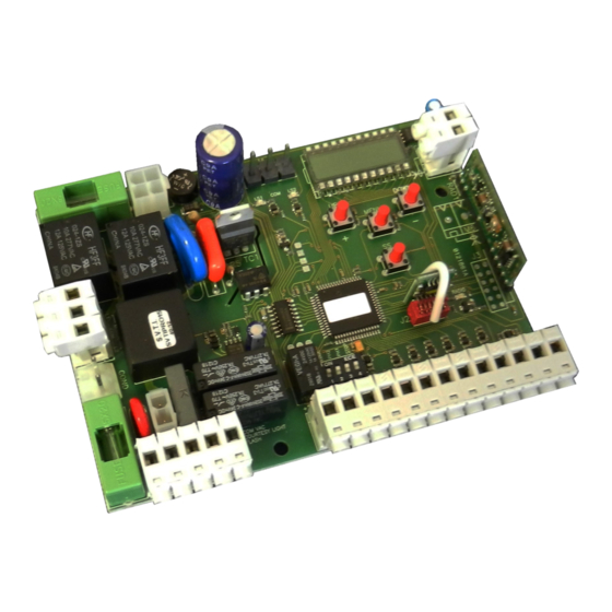
- Page 1 CONTROL UNIT BIOS1 BRT Programmable Control board for barriers BRT Manual for installation...
- Page 2 1. Introduction The control unit BIOS1 BRT is particularly indicated for barriers 230 Vac motor with maximum power absorbed of 700W. The control unit is equipped with a display that allows a precise regulation of the thrust. The control unit can memorize up to 1000 transmitters (8000 as optional), with the step by step, partial opening, open and close functions.
- Page 3 POWER SUPPLY Power supply 230 Vac 50 Hz Connect the power supply cable between clamp Do not connect the card directly to the electric 1 and 2 of the control unit network. Put a device which can ensure the disconnection of each pole from the power supply of the control unit.
- Page 4 4. Installation sample Closing loop Photocell Photocell Barrier BRT Zone loop Photocell Photocell Safety edge Command device Opening loop 5. Remote control learning 5.1 Learning of one transmitter A transmitter is memorized a key at a time: The 1 memorized key performs the OPEN function, the 2 key performs CLOSE function, the 3 performs the STEP by STEP function (opening and closing of the gate) and the 4 key performs the partial opening.
- Page 5 6 Setting stroke 6.1 Easy settings of the stroke (parameter ≠ ) Be sure that the limit switches are connected and correctly adjusted (see mechanical instruction) Be sure that the barrier is positioned in the middle of the stroke. Limit switches must not be activated. Unlock the barrier and move it to the middle of the stroke The barrier moves in opening.
- Page 6 7. Menu Ex. Base menu Entering the menu: To enter the base menu settings keep pressed the MENU button for at least one second To enter the advanced menu settings keep pressed the MENU button for at least five seconds Navigation into the menu: Ex.
- Page 7 7.2 Advanced menu: VALORI IMPOSTABILI MENU DESCRIZIONE DEFAULT UNITÀ min-max PH2 multifunction input setting: 0 = Closing photocell 1 = Closing loop NO 2 = Closing loop NC 3 = Zone loop NO 4 = Zone and closing loop NO 5 = Loop for enable command OPEN 6 = Clock Photocells test...
- Page 8 7.3 Menu description: 7.3.1 Base settings menu Auto reclosing time Active when the barrier is in the completely open position or in partial opening, the barrier automatically closes after seconds. In this phase the display shows with the blinking dash, that during the last 10 seconds will be replaced by the count down. Auto reclosing time after transit If in the opening phase or in the completely open position the beam of the PH1 photocells is obscured and freed, the barrier automatically closes after ...
- Page 9 7.3.2 Advanced menu .. PH2 multifunction input setting Closing loop The control unit has six different functionings for PH2: .. = 0 Closing photocell: - Closing: immediate inversion of movement. - Opening: no intervention during the movement. - With barrier stopped, not allow the closing. ...
- Page 10 .. Flashing light output mode It is possible to choose 2 different functioning for the blinker output: .. = 0 Fixed blinker output. It will be necessary to connect a self flashing blinker (B.RO LIGHT 230 Vac) .. = 1 Flashing light blinker output. It will be necessary to connect a fix light blinker (B.RO LIGHT FIX 230 Vac) ..
- Page 11 8. Display and control unit state 8.1 Normal functioning: Standby - Barrier closed or after the switch on of the control unit (no in open position). Opening phase Closing phase Barrier stopped by user during the opening Barrier stopped by user during the closing Barrier stopped by an external event (photocell, stop) Barrier opened without automatic reclosing Barrier opened in partial opening position without automatic reclosing...
-
Page 12: Power Supply And Consumption
Tel. 0437 751175 – 751163 r.a. Fax 0437 751065 http://www.allmatic.com - E-mail: info@allmatic.com GUARANTEE - In compliance with legislation, the manufacturer’s guarantee is valid from the date stamped on the product and is restricted to the repair or free replacement of the parts accepted by the manufacturer as being defective due to poor quality materials or manufacturing defects. The guarantee does not cover damage or defects caused by external agents, faulty maintenance, overloading, natural wear and tear, choice of incorrect product, assembly errors, or any other cause not imputable to the manufacturer.
Need help?
Do you have a question about the BIOS1 BRT and is the answer not in the manual?
Questions and answers