
Subscribe to Our Youtube Channel
Related Manuals for Allmatic BIOS1 RNS


Summary of Contents for Allmatic BIOS1 RNS
- Page 1 BIOS1 RNS CONTROL UNIT FOR SLIDING GATES CONTROL UNIT FOR SLIDING GATES INSTALLATION AND USE MANUAL BIOS1 230V RNS BIOS1 120V RNS 6-1622460M - rev. 1 - 04/03/2024 ENGLISH - Translated from the original language...
- Page 2 INDEX 1. GENERAL WARNINGS FOR THE INSTALLER 1.1 - GUIDELINES ON ELECTRICAL CONNECTIONS 2. PRODUCT DESCRIPTION 2.1 - INTENDED USE 2.2 - TECHNICAL CHARACTERISTICS 2.3 - VIEW OF THE ELECTRONIC BOARD 3. ELECTRICAL CONNECTION 3.1.1 - CONNECTION OF MAIN POWER SUPPLY AND TRANSFORMER (230V version) 3.1.2 - CONNECTION OF MAIN POWER SUPPLY AND TRANSFORMER (120V version) 3.2.1 - MOTOR CONNECTION (230V version) 3.2.2 - MOTOR CONNECTION (120V version)
- Page 3 1. GENERAL WARNINGS FOR THE INSTALLER DANGER RISK OF ELECTRIC SHOCK, EXPLOSION OR ELECTRIC ARC • Shut down all equipment, including connected devices, before removing any lid or door, or before installing/uninstalling accessories, hardware, cables or wires, except for the conditions specified in the user manual for this equipment.
- Page 4 WARNING GENERAL ASPECTS OF SAFETY AND REGULATORY INCOMPATIBILITY • Any use of this product other than the permitted use /intended use is prohibited. • The manufacturer cannot be held responsible for any damage that occurs as a result of improper use or as a result of an installation that does not comply with the requirements of this manual.
- Page 5 1.1 - GUIDELINES ON ELECTRICAL CONNECTIONS Prepare cable ducts on the installation site. The cables for the connection of the various devices in a typical plant are listed in the table below and must be suitable for the type of installation, for example we recommend a cable type H07RN-F for outdoor installation. CONNECTION CABLE LENGTH...
- Page 6 Insulation class Degree of pollution Frequency of radio communication 433,92 Mhz Compatible remote controls Rolling Code, Allmatic protocol Number of remote controls that can be stored 1000 Environmental operating conditions TA: -20...+55 °C RH max 90% non-condensing Conditions of transport and storage TA: -40...+70 °C RH max 90% non-condensing...
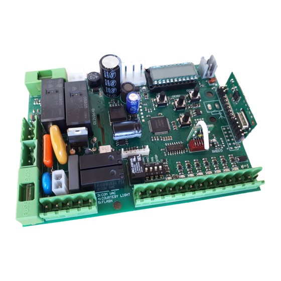
- Page 7 2.3 - VIEW OF THE ELECTRONIC BOARD 1 2 3 4 5 6 7 8 9 10 11 12 13 14 15 16 17 18 Display and buttons Radio Memory Radio Module LED Radio DIP-SWITCH selector for the exclusion of safety inputs FUSE1 - Line Protection (6.3 A F) FUSE2 - Protection 24 Vdc accessories (500 mA F) Terminal block for motor connection...
- Page 8 3. ELECTRICAL CONNECTION 3.1.1 - CONNECTION OF MAIN POWER SUPPLY AND TRANSFORMER (230V version) # TERMINAL FUNCTION DESCRIPTION L - Phase cable Connect power from network distribution 230 Vac 10% 50/60 Hz N - Neutral cable Connect the 230 / 23 Vac 15 VA transformer to the control board connectors. ...
- Page 9 3.2.1 - MOTOR CONNECTION (230V version) # TERMINAL FUNCTION DESCRIPTION L1 - Phase 1 of the motor Connect two-phase electric motor cables COM - Neutral Phase of the motor 230Vac MAX 700W. L2 - Phase 2 of the motor Capacitor cable Use a capacitor suitable for the type of electric motor in use.
- Page 10 3.3 - CONNECTION OF ELECTRO-MECHANICAL LIMIT SWITCHES # TERMINAL FUNCTION DESCRIPTION LS1 - Limit switch 1 contact Connect a clean contact (voltage free) Normally Common contact of limit switches Closed. LED indicator Normally ON. LS2 - Limit switch 2 contact LIMIT SWITCH LS2 LIMIT SWITCH LS1 3.4 - POWER SUPPLY CONNECTION FOR ACCESSORIES...
- Page 11 3.5 - ELECTRICAL CONNECTIONS OF CONTROL DEVICES # TERMINAL FUNCTION DESCRIPTION COMMON CONTACT OPEN Connect a clean contact (voltage free) Normally CLOSE Open. PARTIAL OPENING LED signal Normally OFF. STEP-BY-STEP STEP-BY-STEP function At each activation it performs in sequence the OPEN-STOP-CLOSE-STOP functions. Refer to the basic parameters to customize the way functions are performed.
- Page 12 3.6 - ELECTRICAL CONNECTIONS OF SAFETY DEVICES NOTE If EDGE, PH2, PH1 and STOP contacts are not used, they must be disabled using the DIP-SWITCH selector. This operation is possible by placing the corresponding selector in the ON position. # TERMINAL FUNCTION DESCRIPTION COMMON CONTACT...
- Page 13 # TERMINAL FUNCTION DESCRIPTION Connect mechanical (NC) or resistive (8.2 9 - 10 SAFETY EDGE Kohm) sensitive edges. Signal LED Normally On. SAFETY EDGE input During the closing movement, it stops the movement of the automation and performs a reversal until the gate reaches the OPEN GATE position.
- Page 14 3.7 - ELECTRICAL CONNECTIONS OF SIGNALLING DEVICES # TERMINAL FUNCTION DESCRIPTION Common courtesy and flashing light output Courtesy light MAX 60 W Flashing light MAX 60 W The outputs are active during the opening and closing phases of the automation. Refer to the advanced parameters to configure the flashing mode and the lighting time of the courtesy light.
- Page 15 4. PROGRAMMING DANGER The operations described in this chapter to finalize the installation must be carried out in the presence of voltage, therefore they must be carried out only by experienced personnel, qualified and taking all neces- sary precautions to ensure safe execution. Check that the operating area is free from any obstacles.
- Page 16 4.2 - DISPLAY MODE The display available in the control unit allows you to view a lot of information such as the status of the automation, the number of movements performed, anomalies detected, etc. There are 4 types of views available. To switch from one type to another press the DOWN button.
- Page 17 4.3 - STANDARD VIEW DISPLAY DESCRIPTION Standing by after power supply connection. Automation in CLOSED GATE position. Automation stops in OPEN GATE position, without automatic closing. Automation stops in the PARTIAL OPENING position, without automatic closing. Automation in opening movement. Automation in closing movement.
- Page 18 4.4 - LEARNING OF A REMOTE CONTROL The learning of a transmitter can be activated via the UP button of the control unit or via the hidden button of a transmitter already stored. The control unit can store up to 1000 remote controls (with memory card) and each of them can associate up to 4 functions, no more than one function per key available.
- Page 19 LEARNING WITH THE HIDDEN BUTTON OF A LEARNED TRANSMITTER NOTE • The use of the hidden button, if present, of a transmitter already learned involves the entry in learning mode of all the automations in which it is associated. Make sure that unwanted remote controls are not learned.
- Page 20 4.5 - LEARNING OF THE STROKE AND LIMIT ADJUSTMENT At the first installation it is necessary to adjust the intervention position of the limit switches and perform a learning procedure to detect the total length of the stroke, the length of the slowdowns and all other areas of the installation necessary for the correct functioning of the automation.
- Page 21 STANDARD PROCEDURE FOR LEARNING With standard learning, the control unit performs all the procedure and the calculation of slowdowns, which will be regulated with the same amplitude both in opening and closing ( see basic parameter " LsI"). DANGER • Check that during the first movement the display displays "LOP" and the gate moves in the OPENING DIRECTION.
- Page 22 LEARNING WITH PERSONALIZED SLOWDOWNS With personalized learning, the amplitudes of the slowdowns are adjusted by the user during the learning procedure. DANGER • Check that during the first movement the display displays "LOP" and the gate moves in the OPENING DIRECTION.
- Page 23 4.6 - MENU OF BASIC FUNCTIONS To access the basic function menu, press and hold the MENU button for 1 to 3 seconds. Use the UP and DOWN buttons to scroll through the available features. While displaying a function, the control unit will alternate the display of the item to the value set in it. To change the value of the parameter you are viewing proceed as follows: •...
- Page 24 Sensitivity on obstacle at full speed NOTE • Too high a level of sensitivity could cause an abnormal behavior of the automation depending on the force that the gear motor needs to move the automation. • Adjust this parameter according to current regulations. Set the sensitivity level for the impact sensor to intervene during gate movement.
- Page 25 Normal: ("OPEN" - "STOP" - "CLOSE" - "STOP" - ...) Classic operation of the STEP-BY-STEP mode. During handling, a STEP-BY-STEP control involves stopping the automation. Alternate STOP: ("OPEN" - "STOP" - "CLOSE" - ...) Alternating operation with possibility of STOP during the opening movement. During the closing movement performs a reversal of motion.
- Page 26 4.7 - MENU OF ADVANCED FUNCTIONS To access the advanced features menu, press and hold the MENU button for longer than 5 seconds. Use the UP and DOWN buttons to scroll through the available features. While displaying a function, the control unit will alternate the display of the item to the value set in it. To change the value of the parameter you are viewing proceed as follows: •...
- Page 27 Duration of the deceleration ramp It takes the gate time to change from normal speed to slowdown speed. PARAMETER VALUES DEFAULT from 0 to 30 multiplied by 100 ms 20 = 2000 ms Mode of intervention PH1 photocell input During the closing movement the engagement of the connected photocell on the input PH1 always involves the reversal of the motion and consequent handling up to the position of "OPEN GATE".
- Page 28 +24V +24V TEST 1 2 3 4 5 COM NO Type of security edge installed Select the type of safety edge connected to the EDGE input. PARAMETER VALUES DEFAULT 0 = mechanical type (Contact Normally Closed) 1 = resistive type (8,2 Kohm) Mode of intervention EDGE input Customize the behavior of the control unit following the intervention of the device connected to the EDGE input.
- Page 29 Auto-test function of the EDGE input WARNING • Activation of the EDGE input auto-test function contributes to the achievement of safety standards throughout the connected control line. Refer to the instruction manual of the connected device for the degree of safety achieved. NOTE •...
- Page 30 Configuration of the flashing output Customize the behavior of the flashing output according to the type of connected device. PARAMETER VALUES DEFAULT 0 = Flashing light with self-flashing circuit 1 = Flashing without self-flashing circuit Flashing time before handling Set how long the flashing output is activated before starting handling. PARAMETER VALUES DEFAULT...
- Page 31 Maintained control function (DEAD-MAN) Enables the possibility to move the automation only by holding down the desired command. Once the command is released, the automation stops. Activating this function results in the following functional changes: • The "Step-by-Step" and "Partial Opening" commands are disabled. •...
- Page 32 Function of Soft Stop It allows to adjust the deceleration ramp in case of request of stop by user command or in case of intervention of the photocell inputs (PH1 and PH2). This parameter DOES NOT modify the deceleration ramp in case of intervention of the EDGE (safety coast) and STOP input.
- Page 33 Cancellation of a single transmitter learned With this parameter you can erase a single transmitter already learned, using its memory location. If this value is not known, refer to the function "Viewer memory location of a learned transmitter". Follow these steps to cancel: •...
- Page 34 4.8 - PASSWORD MANAGEMENT WARNING • Carefully store the 5-digit sequence used to set the password. • If you lose your password, please contact your reseller to restore the system. A 5-digit password can be set using the advanced PASS parameter. Once the setting is made, access to all the parameter menus will always be preceded by the request to enter the password.
- Page 35 ENTER THE PASSWORD TO ACCESS THE MENUS When you press the MENU button, the control panel prompts you to enter the password to access it. After 2 minutes of inactivity, the control panel automatically exits the password entry screen. ...
- Page 36 5. ERROR MESSAGES NOTE Message reporting persists as long as the event persists or until the DOWN key is pressed or a handling command is executed. DISPLAY DESCRIPTION SOLUTION • Check that the limit switch is not blocked. Limit switch error: Opening and closing limit •...
- Page 37 6. MAINTENANCE DANGER • Before carrying out any cleaning, maintenance or replacement of parts, remove power to the automation. • The following points are specific to the maintenance of the control panel. The list does not cover mainte- nance activities specific to the sliding gate/door. Every 10,000 cycles and in any case every 6 months of activity, the following maintenance interventions are mandatory: •...
- Page 38 /allmaticsrl ALLMATIC S.r.l 32026 Borgo Valbelluna - Belluno – Italy @allmaticsrl Via dell’Artigiano, n°1 – Z.A. Tel. 0437 751175 – 751163 r.a. Fax 0437 751065 E-mail: info@allmatic.com @AllmaticSrl www.allmatic.com...
Need help?
Do you have a question about the BIOS1 RNS and is the answer not in the manual?
Questions and answers