Advertisement
Available languages
Available languages
Quick Links
Advertisement

Related Manuals for Allmatic BIOS2 24V


Summary of Contents for Allmatic BIOS2 24V
- Page 1 BIOS2 24V CENTRALINA PER CANCELLI A BATTENTE 24V MADE IN ITALY...
- Page 2 ATTENZIONE! Prima di installare il prodotto è obbligatorio leggere il documento relativo alle AVVERTENZE DI SICUREZZA GENERALI a corredo del prodotto. Documento 6-1620001. Il foglio integrativo è scaricabile anche dal sito www.allmatic.com. 2 - SELEZIONE MOTORIZZAZIONE IN USO ATTENZIONE! Prima di eseguire gli apprendimenti delle corse, la memorizzazione dei trasmettitori e prima di eseguire qualsiasi altra impostazione, è...
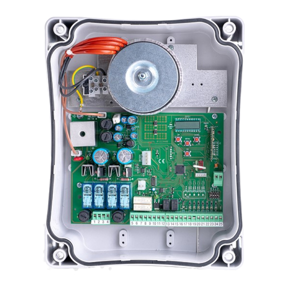
- Page 3 3 - DESCRIZIONE PRODOTTO La centrale di comando BIOS2 24V è indicata per le installazioni a 2 motori 24Vdc e un assorbimento massimo di 10A. Il suo funzionamento è facile e intuitivo grazie all’interfaccia display e ai 4 tasti. Il quadro di comando permette una regolazione precisa di tutti i parametri. La centrale può memorizzare fino a 1000 trasmettitori (memoria esterna) con la funzione passo-passo, apertura parziale, apri e chiudi.
- Page 4 3.2 - MODELLI E CARATTERISTICHE TECNICHE CODICE DESCRIZIONE 12006661 Centrale BIOS2 24V per due motori 60551000 Trasformatore 230 / 23 Vac 150VA 60551040 Trasformatore 230 / 23 Vac 300VA, per motori INT VS. 12006730 Modulo Bluetooth 12000760 Scheda R1 12000780...
- Page 5 Componenti da installare secondo la norma EN12453 USO DELLA CHIUSURA TIPO DI COMANDO Persone esperte (fuori Persone esperte Uso illimitato da area pubblica*) (area pubblica) a uomo presente non possibile a impulsi in vista C o E C o E C e D, o E (es.
- Page 6 Numero Nome Descrizione 3 - 4 Collegare l’alimentazione del motore 2. 5 - 6 24VDC Alimentazione accessori 24Vdc. ATTENZIONE La centrale fornisce fino a un massimo di 200mA (5W) per tutti gli accessori a 24Vdc. 7 - 8 FLASH Uscita lampeggiante a 24Vac. Utilizzare un lampeggiante senza autolampeggio 24Vac 25W max.
- Page 7 5 - DISPLAY E STATI DELLA CENTRALE DOWN MENU Premendo il tasto “DOWN” si possono leggere sul display i seguenti parametri. DISPLAY DESCRIZIONE Visualizzazione stato (--, OP, CL, ...) Descrizione dello stato della centrale. Fare riferimento alla tabella STATI DELLA CENTRALE per la descrizione dei singoli stati di funzionamento. Manovre eseguite, esempio: Conteggio delle manovre: si alternano le migliaia (senza puntini) e le 02.0.
- Page 8 POWER DOWN 5.3 - SEGNALAZIONI ANOMALIE MENU DISPLAY DESCRIZIONE Errore memoria: memoria esterna non montata o non riconosciuta. Errore scrittura memoria: il valore x è un numero da 1 a 6. In caso di errore contattare l’assistenza tecnica. Intervento sensore di impatto. Intervento costa di sicurezza.
- Page 9 L’apprendimento di un trasmettitore può essere attivato tramite il tasto “UP” della centralina o tramite il tasto nascosto di un trasmettitore già memorizzato. La centrale BIOS2 24V può memorizzare fino a 4 funzioni in altrettanti tasti del radiocomando. Durante la procedura d’apprendimento, illustrata al DOWN paragrafo 6.1, si memorizza il singolo tasto del trasmettitore.
- Page 10 DOWN MENU 6.2 - APPRENDIMENTO CON IL TASTO NASCOSTO DI UN TRASMETTITORE GIÀ APPRESO DOWN MENU MENU DISPLAY Lampeggiante Ad automazione ferma premere con l’aiuto di una graffetta il tasto nascosto di DOWN ...
- Page 11 7 - APPRENDIMENTO DELLA CORSA NOTA - prima di effettuare l’apprendimento verificare tramite il menu avanzato de.f. (capitolo 9) se il tipo di motore selezionato è corretto. Alla prima accensione è necessario eseguire una procedura di apprendimento per rilevare la lunghezza della corsa e dei rallentamenti. Dopo questa procedura l’installazione è...
- Page 12 Il MOTORE 2 muove automaticamente in chiusura, a velocità piena. Raggiunto il fermo meccanico di chiusura, il motore si ferma automaticamente. ATTENZIONE - se il motore non si ferma automaticamente, premere il tasto “SS”. DOWN In questa fase il display mostra LCL. MENU ...
- Page 13 7.2 - APPRENDIMENTO AVANZATO Collegare all’uscita MOTORE 1 l’anta che va in battuta e a cui è collegata un’eventuale elettroserratura. Il MOTORE 1 viene attivato sempre per primo in apertura e per secondo in chiusura. Effettuare un controllo delle impostazioni ed eventualmente personalizzarle prima di effettuare l’apprendimento.
- Page 14 DOWN Il MOTORE 1 muove automaticamente in chiusura, a velocità piena. MENU Quando l’automazione raggiunge la posizione di inizio rallentamento fornire un comando passo passo (SS). DOWN In questa fase il display mostra LCL. DOWN MENU MENU ...
- Page 15 8 - MODIFICA PARAMETRI - MENU BASE DOWN È possibile accedere a un MENU BASE per la modifica dei parametri principali dell’unità di controllo. DOWN MENU Per entrare nel menu, procedere come sotto riportato. MENU ATTENZIONE - dopo 2 minuti di inattività la centrale esce automaticamente dal menu. ...
- Page 16 DEFAULT PARAMETRI DESCRIZIONE UNITÀ CUSTOM Ritardo seconda anta. Ampiezza rallentamento: P = personalizzato da apprendimento. 0…100% = percentuale della corsa. Antislittamento / Tempo extra. Numero motori: 1 = 1 motore. 2 = 2 motori. NOTA - i parametri evidenziati in grigio dipendono dal motore selezionato. In tabella vengono riportati i dati del motore CUSTOM. Per maggiori dettagli fare riferimento al capitolo 12.
- Page 17 RITARDO SECONDA ANTA dLY Permette di definire lo sfasamento tra le ante allo scopo di evitare che si accavallino durante il moto. 10. AMPIEZZA RALLENTAMENTO LSI Con questo parametro è possibile definire l’ampiezza dei rallentamenti ed eventualmente la loro esclusione ( LSI= 0 ). Nel caso si desideri avere rallentamenti più...
- Page 18 DEFAULT PARAMETRI DESCRIZIONE UNITÀ CUSTOM Tempo richiusura automatica da apertura parziale (0 = disabilitato). Configurazione uscita lampeggiante: 0 = fissa. 1 = lampeggiante. Tempo prelampeggio (0 = disabilitato). Configurazione luce di cortesia: 0 = a fine manovra accesa per tempo TC.Y. 1 = accesa se automazione non chiusa + durata TC.Y.
- Page 19 • sn.m. = 2 il sensore interviene solo come ostacolo, a prescindere dalla posizione. • sn.m. = 3 il sensore interviene solo come fine movimentazione, a prescindere dalla posizione. AMPIEZZA AREA DI RESYNC MI.A. Con questo parametro è possibile definire l’ampiezza dell’area di resync ed eventualmente la sua esclusione ( MI.A.= 0 ). In questa zona, l’intervento del sensore di corrente arresta il movimento e imposta la posizione raggiunta come posizione di chiusura / apertura totale.
- Page 20 • fC.y. = 3 spia automazione aperta - la luce si spegne immediatamente al raggiungimento della posizione di chiusura totale. • fC.y. = 4 spia automazione aperta con lampeggio proporzionale allo stato dell’automazione: – Apertura: lampeggio lento. – Chiusura: lampeggio veloce. –...
- Page 21 stampa SEE, rilasciare il tasto. A questo punto premere un pulsante del trasmettitore memorizzato (non attiva alcun comando). Il display mostra: • la posizione nella memoria per 2 secondi, se era stato memorizzato; • la scritta not per 2 secondi, se non era stato memorizzato. Trascorsi 2 secondi il display torna alla schermata SEE e sarà...
- Page 22 DOWN DOWN DOWN DOWN DOWN DOWN MENU MENU MENU 11 - APPRENDIMENTO DELLA CORSA - SINGOLO MOTORE MENU MENU MENU Selezionare il funzionamento con un motore: ...
- Page 23 ATTENZIONE - in caso di intervento di un dispositivo di sicurezza, la procedura viene arrestata e appare a display la scritta Premere il tasto “SS” per ricominciare l’apprendimento dal punto 4. NOTA - se i motori non si fermano automaticamente durante l’apprendimento, incrementare i valori della sensibilità su ostacolo e/o della sensibilita su ostacolo in rallentamento (menu SEN e SEL), vedere paragrafo 8, e verificare che la modalità...
- Page 24 12 - VALORI DI DEFAULT La centralina BIOS2 24V ha la possibilità di selezionare il modello del motore utilizzato. Questo permette di configurare di default alcuni parametri per il funzionamento ottimale del motore. Di seguito viene inserita la tabella dei parametri dipendenti dal motore con il valore di default assegnato.
- Page 25 BIOS2 24V CONTROL UNIT FOR WING GATES AT 24V MADE IN ITALY...
- Page 26 WARNING! Before installing the product, it is mandatory to read the document relating to GENERAL SAFETY WARNINGS supplied with the product. Document 6-1620001. The supplementary sheet can also be downloaded from www.allmatic.com. 2 - SELECTION OF THE MOTOR WARNING! Before executing the learning of the strokes, the memorization of the transmitters and before performing any other setting, it is necessary to select the motorization in use, this allows to optimize the operation of BIOS2 24.
- Page 27 3 - PRODUCT DESCRIPTION The control unit BIOS2 24V is suitable for the installations of 2 motor with direct current 24V and a maximum absorption of 10A. This device has an easy and intuitive functioning thanks to the display interface and 4 buttons. The control unit allows a precise regulation of all parameters. The control unit can memorize up to 1000 transmitters (external memory) with the step by step, partial opening, open and close functions.
- Page 28 3.2 - MODELS AND TECHNICAL FEATURES CODE DESCRIPTION 12006661 BIOS2 24V control unit for two motors 60551000 Transformer 230 / 23 Vac 150VA 60551040 Transformer 230 / 23 Vac 300VA, for INT VS motors. 12006730 Bluetooth module 12000760 R1 card...
- Page 29 Parts to install meeting the EN 12453 standard USE OF THE SHUTTER COMMAND TYPE Skilled persons Skilled persons Unrestricted use (out of public area*) (public area) with manned operation non possibile with visible impulses C or E C or E C and D, or E (e.g.
- Page 30 Number Name Description 3 - 4 Connect the motor 2. 5 - 6 24VDC 24Vdc accessories power supply. WARNING - The control unit supplies up to a maximum of 200 mA (5W) for all the accessories at 24Vdc. 7 - 8 FLASH Flashing light output at 24Vac.
- Page 31 5 - DISPLAY AND STATES OF THE CONTROL UNIT DOWN MENU By pressing the “DOWN” button it is possible to read on the display the following parameters. DISPLAY DESCRIPTION State showing (--, OP, CL, ...) Description of the control unit state. Refer to the STATES OF THE CONTROL UNIT table for the description of the single states of functioning.
- Page 32 POWER DOWN 5.3 - MALFUNCTION SIGNALLINGS MENU DISPLAY DESCRIPTION Memory error: the external memory not installed or not recognised. Memory error during the writing: the value x is a number from 1 to 6. In the event of the error, contact the technical assistance. Impact sensor intervention.
- Page 33 The learning of a transmitter can be enabled with the “UP” button of the control unit or with the hidden key of a transmitter already memorized. The BIOS2 24V control unit can memorize up to 4 functions in as many keys of the remote control. During the learning procedure, described at DOWN paragraph 6.1, a single key is stored.
- Page 34 DOWN MENU 6.2 - LEARNING WITH THE HIDDEN KEY OF A TRANSMITTER ALREADY MEMORIZED DOWN MENU MENU DISPLAY Blinker DOWN With the automation steady, with the aid of a clip press the hidden key of a ...
- Page 35 7 - SETTING OF THE STROKE NOTE - check with the advanced menu de.f.(chapter 9) if the selected motor type is correct, before carring out the learning. At the first power up, it is necessary to carry out a learning of the stroke for the acquisition of the stroke length and the slowdowns. After this procedure the installation is complete.
- Page 36 The MOTOR 2 moves automatically in closing, at running speed. Reached the closing mechanical stop, the motor stops automatically. WARNING - if the motor doesn’t stop automatically, press the “SS” button. DOWN In this phase the display shows LCL. MENU ...
- Page 37 7.2 - ADVANCED SETTINGS OF THE STROKE Connect to the MOTOR 1 output the wing which beats. Install an aventual electrical lock on this wing. MOTOR 1 is always activated first during opening phase and in second during closing phase. Carry out a check of the menus and, if needed, customize the settings before the learning of the stroke.
- Page 38 DOWN The MOTOR 1 moves automatically in closing, at running speed. MENU When the automation reaches the position for the beginning of the slowdown, give a Step-by-Step command (SS). DOWN In this phase the display shows LCL. DOWN MENU MENU...
- Page 39 8 - CHANGE PARAMETERS - BASIC MENU DOWN It is possible to access a BASIC MENU to change the main parameters of the control unit. DOWN MENU To enter the menu, proceed as described below. MENU WARNING - after 2 minutes of inactivity, the control unit exits automatically from the menu. ...
- Page 40 DEFAULT PARAMETERS DESCRIPTION UNIT CUSTOM Second wing delay. Amplitude of slowdown. P = personalized during learning. 0…100% = percentage of stroke. Anti slipping / Extra time. Number of motors: 1 = 1 motor. 2 = 2 motors. NOTE - the parameters highlighted in grey depend on the selected motor. In the table are reported the data of the CUSTOM motor. For more information, refer to chapter 12.
- Page 41 10. AMPLITUDE OF SLOWDOWN LSI With this parameter it is possible to adjust the amplitude of the slowdown and eventually disable it ( LSI= 0 ). If you need more precise or different slowdown between opening and closing it is possible to set the parameter LSIon P (personalized) and perform an advanced learning of strokes providing also the beginning of slowdowns during the learning.
- Page 42 DEFAULT PARAMETERS DESCRIPTION UNIT CUSTOM Auto reclosing time from partial opening (0 = disabled). Blinker output mode: 0 = fix. 1 = blinking. Pre-flashing time (0 = disabled). Courtesy ligth settings: 0 = at the end of the movement for a TC.Y. time. 1 = on if the automation is not closed + TC.Y.
- Page 43 • sn.m. = 2 the sensor intervenes only for obstacle detection in any position. • sn.m. = 3 the sensor intervenes only as end of the movement in any position. AMPLITUDE OF THE RESYNC AREA MI.A. With this parameter it is possible to adjust the amplitude of the resync area and eventually disable it ( MI.A.= 0 ). In this area, the intervention of the current sensor stops the movement and set the reached position as a full closed / open position.
- Page 44 • fC.y. = 3 open automation light - the light switches off immediately when the automation reaches the closed position. • fC.y. = 4 open automation light with proportional blinking: – Opening: slow blinking. – Closing: fast blinking – Opened: light on –...
- Page 45 SEE, then release the button. At this point press a button of the memorized transmitter (it does not active any command). The display shows: • the memory location for 2 seconds, if is memorized; • the written not for 2 seconds, if is not memorized. After 2 seconds the display returns to the screen SEE and it will be possible to perform this function with another transmitter.
- Page 46 DOWN DOWN DOWN DOWN DOWN DOWN MENU MENU MENU 11 - SETTING OF THE STROKE - SINGLE MOTOR MENU MENU MENU Select the functioning with a single motor: ...
- Page 47 WARNING - in the event of a safety device intervention, the learning is stopped and will appear on the display Press the “SS” button to start again the learning from the 4th point. NOTE - if the motors don’t stop automatically during the learning, increase the value of the obstacle sensitivity and /or the obstacle sensitivity during slowdowns (menu SEN and SEL), see paragraph 8, and check that the intervention mode of the current sensor is suitable for the use as limit switch (menu Sn.M.), see paragraph 9.
- Page 48 12 - DEFAULT VALUES The BIOS2 24V control unit has the possibility to select the used motor. This allows to set, as defaults, some parameters for the optimal functioning of the motor. Here below, the table of the parameters with the default values assigned that depend on the motor.
- Page 49 BIOS2 24V CENTRAL DE COMMANDE POUR PORTAIL BATTANT À MADE IN ITALY...
- Page 50 ATTENTION! Avant d’installer le produit il est obligatoire de lire le dossier concernant LES AVVERTISSEMENTS GÉNÉRALES DE SECURITÉ fournies avec le produit. Dossier 6-1620001. Téléchargeable aussi à partir du site internet www.allmatic.com. 2 - SÉLECTION AUTOMATISATION EN UTILISATION ATTENTION! Avant d’effectuer les apprendissages des courses, l’apprendissages des émetteurs et avant d’effectuer n’importe quoi d’autre configuration, il est necessaire de choisir l’automatisation en utilisation.
- Page 51 3 - DESCRIPTION DU PRODUIT La centrale de commande BIOS2 24V est indiquée pour les installations de 2 moteurs à courant continu 24V et d’une absorption maximum de 10A. Son fonctionnement est simple et intuitif grâce à l’interface d’affichage et aux 4 boutons. Le tableau de commande permet un réglage précis de tous les paramètres.
- Page 52 3.2 - MODÈLES ET CARACTÉRISTIQUES TECHNIQUES CODE DESCRIPTION 12006661 Central de commande BIOS2 24V pour 2 moteurs. 60551000 Transformateur 220 / 23 Vac 150VA. 60551040 Transformateur 220 / 23 Vac 300VA, pour moteurs INT VS. 12006730 Module Bluetooth. 12000760 Carte R1.
- Page 53 Parties à installer conformément à la norme EN12453 USAGE DE LA FERMETURE Personne experte (au TYPE DE COMMANDE Personne experte (Zone dehors d’une zone Usage illimité publique) publique*) A homme mort Non possible A commande en vue C ou E C ou E C et D, ou E (Ex.
- Page 54 Nombre Description 3 - 4 Brancher l’alimentation du moteur 2. 5 - 6 24VDC Alimentation accessoires 24Vdc. ATTENTION: la centrale fournit jusqu’à un maximum de 200mA (5W) pour tous les accessoires à 24Vdc. 7 - 8 FLASH Sortie clignotant à 24 Vac. Utiliser un clignotant sans circuit auto-clignotement 24Vac 25W max.
- Page 55 5 - AFFICHAGE ET ÉTATS DE LA CENTRALE DOWN MENU Appuyer sur la touche “DOWN” pour lire sur l’écran les paramètres suivants. ÉCRAN DESCRIPTION Description de l’état de la centrale. Faites référence à la table ÉTATS DE Visualisation état (--, OP, CL, ...) LA CENTRALE pour la description des états de fonctionnement.
- Page 56 POWER DOWN 5.3 - SIGNALISATION ANOMALIES MENU ÉCRAN DESCRIPTION Erreur mémoire: mémoire externe non installée ou non reconnue. Erreur écriture mémoire: la valeur x est un numéro de 1 à 6. Si une erreur se produit, contactez l'assistance technique. Intervention capteur d’impact. Intervention barre palpeuse.
- Page 57 L’apprentissage d’un émetteur peut être activé par le bouton “UP” de la centrale de commande, ou par la touche cachée d’un émetteur déjà mémorisé. La centrale BIOS2 24V peut mémoriser jusqu’à quatre fonctions dans autant de touches de la télécommande. Pendant la procédure d’apprentissage, expliquée au paragraphe 6.1, on mémorise le bouton individuel de l’émetteur.
- Page 58 DOWN MENU 6.2 - APPRENTISSAGE PAR LA TOUCHE CACHÉE D’UN ÉMETTEUR DÉJÀ APPRIS DOWN MENU MENU DISPLAY Clignotant Quand la motorisation est arrêté, appuyer par l’aide d’une agrafe sur la touche DOWN cachée d’un émetteur déjà...
- Page 59 7 - APPRENTISSAGE DES COURSES NOTE - avant d’effectuer l’apprentissage vérifiez à travers le menu avancé de.f. (chapitre 9) si le type de moteur sélectionné est correct. Lors de la première activation il est nécessaire d’effectuer une procédure d’apprentissage pour détecter la longueur de la course et des ralentissements. Après cette procédure, l’installation est terminée.
- Page 60 Le MOTEUR 2 bouge automatiquement en fermeture à vitesse normale. Une fois atteint le blocage mécanique de fermature, le moteur s’arrête automatiquement. ATTENTION - si le moteur ne s’arrête pas automatiquement, appuyez DOWN sur le bouton “SS”. MENU Le display affiche LCL.
- Page 61 7.2 - APPRENTISSAGE DES COURSES AVANCÉ Brancher à la sortie MOTEUR1 le battant qui batte et à la quelle est connecté une éventuelle serrure électrique. Le MOTEUR 1 est activé toujours en premier et en deuxième en fermeture. Effectuer un contrôle des réglages et éventuellement les personnaliser avant de procéder avec l’apprentissage.
- Page 62 DOWN Le MOTEUR 1 bouge automatiquement en fermeture à vitesse normale. MENU Lorsque la motorisation atteint la position de début ralentissement, fournir une commande étape-par-étape (SS). DOWN Le display affiche LCL. DOWN MENU MENU ...
- Page 63 8 - MODIFICATION DES PARAMETERS - MENU BASE DOWN Il est possible d’accéder au menu de base pour la modification des principaux paramètres de la centrale de commande. DOWN MENU Pour entrer dans le MENU BASE, procéder comme il suit. MENU ATTENTION - Au bout de 2 minutes d’inactivité, la centrale de commande sort automatiquement du menu.
- Page 64 DEFAULT PARAMÈTRES DESCRIPTION UNITE CUSTOM Retard deuxième battant. Amplitude ralentissement : P = personnalisé par l’apprentissage. 0…100% = pourcentage de la course. Anti-glissement / Temps supplémentaire. Nombre des moteurs 1 = 1 moteur 2 = 2 moteurs NOTE - Les paramètres mis en évidence en gris dépendent du moteur sélectionné. Dans le tableau, les données du moteur CUSTOM sont représentées. Pour plus de détails faire référence au chapitre 12.
- Page 65 RETARD DEUXIÈME BATTANT dLY Permet de définir le décalage entre les battants pour éviter qu’ils se superposent pendant le mouvement. 10. AMPLITUDE RALENTISSEMENT LSI Avec ce paramètre, il est possible de définir l’amplitude des ralentissements et éventuellement leur exclusion (LSI = 0). Au cas où on souhaite des ralentissements plus précis ou différents pour chaque direction/battant, il est possible de régler le paramètre LSI sur P (personnalisés) et exécuter l’apprentissage des courses avancé...
- Page 66 DEFAULT PARAMÈTRES DESCRIPTION UNITE CUSTOM Temps fermeture automatique ouverture partielle (0 = désactivé). Configuration sortie clignotant: 0 = fixe. 1 = clignotant. Temps pré-clignotement (0 = désactivé). Configuration lumière de courtoisie : 0 = a la fin du mouvement, allumée pendant le temps TC.Y. 1 = allumée si la motorisation n’est pas fermé...
- Page 67 • sn.m. = 2 le capteur intervient seulement en tant qu’obstacle, indépendamment de la position. • sn.m. = 3 le capteur intervient seulement en tant que fin du mouvement, indépendamment de la position. AMPLEUR ZONE DE RESYNC MI.A. Avec ce paramètre, il est possible de définir l’ampleur de la zone de resync et éventuellement son exclusion ( MI.A.= 0 ). Dans cette zone, l’intervention du capteur de courant arrête le mouvement et règle la position atteinte en tant que position de fermeture/ouverture totale.
- Page 68 la fin du mouvement). • fC.y. = 3 voyant motorisation ouverte - la lumière s’éteint immédiatement lorsque la position de fermeture totale est atteinte. • fC.y. = 4 voyant motorisation ouverte avec clignotement proportionnel à l’état de l’automatisme: – Ouverture: clignotement lent. –...
- Page 69 30. AFFICHAGE DE LA POSITION DE CHAQUE ÉMETTEUR DANS LA MÉMOIRE TR.S. En accédant à l’option tr.S. il est possible de visualiser la position dans la mémoire dans la quelle un émetteur a été mémorisé. Pour activer la fonction, accédez à l’option tr.S. - puis validez en appuyant sur le bouton “MENU”. Gardez appuyé jusqu’à ce que sur l’écran apparait SEE, ensuite relâchez le bouton.
- Page 70 DOWN DOWN DOWN DOWN DOWN DOWN MENU MENU MENU 11 - APPRENTISSAGE DES COURSES - 1 MOTEUR MENU MENU MENU Sélectionner le fonctionnement avec un moteur: ...
- Page 71 ATTENZIONE - in caso di intervento di un dispositivo di sicurezza, la procedura viene arrestata e appare a display la scritta Premere il tasto “SS” per ricominciare l’apprendimento dal punto 4. NOTE - Si les moteurs ne s’arrêtent pas automatiquement lors de l’apprentissage, augmenter la valeur de la sensibilité sur obstacle et/ou de la sensibilité...
- Page 72 12 - VALEURS PAR DEFAULT La centrale de commande BIOS2 24V a la possibilité de sélectionner le modèle du moteur utilisé. Cela vous permet de configurer certains paramètres par défaut, pour le fonctionnement optimal du moteur. Veuillez trouver ci-dessous la table des paramètres dépendants du moteur, avec la valeur par défaut attribuée.
- Page 73 BIOS2 24V CUADRO DE MANDO PARA CANCELAS A HOJA 24V MADE IN ITALY...
- Page 74 CUIDADO! Antes de instalar el producto es obligatorio leer el documento relativo a las ADVERTENCIAS DE SEGURIDAD GENERAL en dotación con il producto. Documento 6-1620001. La página integrativa se puede descargar tambien del sitio www.allmatic.com. 2 - SELECCIÓN DE LA MOTORIZACIÓN EN USO CUIDADO! Antes de realizar los aprendizajes de los recorridos, la memorización de los mandos y antes de realizar...
- Page 75 3 - DESCRIPCIÓN DEL PRODUCTO La central de mando BIOS2 24V es indicada para la instalación de 2 motores 24 Vdc con absorción máxima de 10A. Su funcionamiento es fácil e intuitivo gracias al interfaz display y a las 4 teclas. El cuadro de mando permite una regulación precisa de todos los parámetros. La central puede memorizar hasta 1000 mandos (memoría externa) con la función paso-paso, apertura parcial, abre y cierra.
- Page 76 3.2 - MODELOS Y CARACTERÍSTICAS TÉCNICAS CÓDIGO DESCRIPCIÓN 12006661 Cuadro de mando BIOS2 24V para 2 motores 60551000 Transformador 230 / 23 Vac 150VA 60551040 Transformador 230 / 23 Vac 300VA para motores INT VS 12006730 Módulo bluetooth 12000760 Placa R1 12000780 Placa cargadora de batería 24CBA...
- Page 77 Componentes a instalar según la norma EN12453 USO DEL CIERRE TIPO DE MANDO Personas expertas (fuera Personas expertas Uso ilimitado de un área pública*) (área pública) en presencia de alguien no posible con impulsos a la vista (ej. C o E C o E C e D, o E sensor)
- Page 78 Número Nombre Descripción 3 - 4 Conectar la alimentación del motor 2. 5 - 6 24VDC Alimentación accesorios 24Vdc. CUIDADO: La central suministra hasta un máximo de 200mA (5W) para los accesorios de 24Vdc. 7 - 8 FLASH Salida luz intermitente de 24Vac. Utilizar una luz intermitente sin autodestello 24Vac 25W max. 9 -10 OPEN GATE LIGHT Salida luz de cortesía / luz indicadora automatización abierta de 24Vac.
- Page 79 5 - DISPLAY Y ESTADO DE LA CENTRAL DOWN MENU Presionando el pulsador “DOWN“ en la pantalla se pueden leer los siguientes parámetros: DISPLAY DESCRIPCIÓN Visualización estado (--, OP, CL, ...) Descripción del estado de la central. Hacer referencia al cuadro ESTADOS DE LA CENTRAL para la descripción de cada estado de funcionamiento.
- Page 80 POWER DOWN 5.3 - SEÑALIZACIÓN ERRORES MENU DISPLAY DESCRIPCIÓN Error memoría: memoria externa no montada o no reconocida. Error escritura memoria: el valor x es un número de 1 a 6. En caso de error contactar la asistencia técnica. Intervención sensor de impacto. Intervención banda de seguridad.
- Page 81 El aprendizaje de un mando puede ser activado por medio de la tecla “UP” de la central o por la tecla escondida de un mando memorizado. La central BIOS2 24V puede memorizar hasta 4 funciones otras tantas teclas del mando. Durante el procedimiento de aprendizaje, mencianado en el parágrafo 6.1, se memoriza la singular tecla del mando.
- Page 82 DOWN MENU 6.2 - APRENDIZAJE CON LA TECLA ESCONDIDA DE UN MANDO YA MEMORIZADO DOWN MENU MENU DISPLAY Intermitente Con la automatización cerrada presionar con la ayuda de una grapa, la DOWN tecla escondida de un mando memorizado;...
- Page 83 7 - APRENDIZAJE RECORRIDO NOTA – antes de realizar el aprendizaje verificar por medio del menu avanzado de.f. (capítulo 9) si el tipo de motor seleccionado es correcto. Con el primer encendido es necesario realizar un procedimiento de aprendizaje para relevar la longitud del recorrido y de las deceleraciones. Luego este procedimiento la instalación se ha realizado.
- Page 84 El MOTOR 2 mueve automáticamente en el cierre, a velocidad plena. Alcanzado el paro mecánico de cierre, el motor se detiene automáticamente. CUIDADO – si el motor no se detiene automáticamente, presionar la tecla “SS”. DOWN El display muestra LCL. MENU ...
- Page 85 7.2 - APRENDIZAJE AVANZADO Conectar la salida del MOTOR 1 la hoja que se cierra primero y a la cual se conecta eventualmente la electrocerradura. El MOTOR 1 se activa siempre primero en apertura y segundo en cierre. Efectuar un control de las regulaciones y eventualmente personalizar antes de efectuar el aprendizaje.
- Page 86 DOWN El MOTOR 1 mueve automáticamente en el cierre, a velocidad plena. MENU Cuando la automatización alcanza la posición de inicio desaceleración suministrar un mando paso paso (SS). DOWN El display muestra LCL. DOWN MENU MENU ...
- Page 87 8 – MODIFICACION PARAMETROS - MENU BASICO DOWN Es posible acceder a un MENU BASICO para la modificación de los parámetros principales de la unidad de control. DOWN MENU Para entrar en el MENÚ BÁSICO proceda de la siguiente manera. MENU CUIDADO - la central sale del menù...
- Page 88 DEFAULT PARÁMETROS DESCRIPCIÓN UNIDAD CUSTOM Retraso segunda hoja. Amplitud desaceleración: P = personalizado de aprendizaje. 0…100% = porcentual del recorrido. Antideslizamiento / Tiempo extra. Número motores 1 = 1 motor 2 = 2 motores NOTA - los parámetros evidenciados en color gris dependen del motor seleccionado. En el cuadro son mencionados los datos del motor CUSTOM. Para mayores detalles remitimos al capítulo 12.
- Page 89 RETRASO SEGUNDA HOJA dLY Permite definir el desfasaje entre las hojas con la finalidad de evitar que se sobreponen durante el movimiento. 10. AMPLITUD DESACELERACIÓN LSI Con este parámetro es posible definir la amplitud de las desaceleraciones y eventualmente su exclusión ( LSI= 0 ). En el caso se desee tener desacelaraciones más precisas o diferentes para cada una de las direcciones/hojas, es posible regular el parámetro LSI en P (personalizados) y realizar el aprendizaje recorrido y los puntos de inicio desaceleración deseados.
- Page 90 DEFAULT PARÁMETROS DESCRIPCIÓN UNIDAD CUSTOM Tiempo cerradura automática desde apertura parcial (0 = deshabilitado). Configuración salida luz destellante: 0 = fija. 1 = intermitente. Tiempo predestello (0 = deshabilitado). Configuración luz de cortesía: 0 = al final de la maniobra encendida por tiempo TC.Y. 1 = encendida si la automatización no está...
- Page 91 • sn.m. = 2 el sensor interviene solo como obstáculo, prescindiendo de la posición. • sn.m. = 3 el sensor interviene solo como final del movimiento, prescindiendo de la posición. AMPLITUD AREA DE RESYNC MI.A. Con este parámetro es posible definir la amplitud del área de resync y eventualmente su exclusión ( MI.A.= 0 ). En esta zona, la intervención del sensor de corriente detiene el movimiento y regula la posición alcanzada como posición de cierre / apertura total.
- Page 92 • fC.y. = 1 la luz se apaga solo con la automatización cerrada luego de haber esperado el tiempo tC.y. regulado. • fC.y. = 2 encendida hasta el vencimiento del tiempo tC.y. regulado, independientemente del estado de la automatización (la luz podria apagarse antes del fin del desplazamiento).
- Page 93 30. VISUALIZACIÓN POSICIÓN DE MEMORIA INDIVIDUAL DEL MANDO TR.S. Entrando en tr.S. es posible visualizar la posición en la memoria en la cual un transmisor ha sido memorizado. Para realizar la función entrar en tr.S. por lo tanto confirmar con la presión prolongada de la tecla “MENU”. Mantener presionada hasta que el display imprime SEE, liberar la tecla.
- Page 94 DOWN DOWN DOWN DOWN DOWN DOWN MENU MENU MENU 11 - APRENDIZAJE RECORRIDO - 1 MOTOR MENU MENU MENU Seleccionar el funcionamiento con un motor: ...
- Page 95 CUIDADO - en el caso de intervención de un dispositivo de seguridad, el procedimiento se detiene y aparece en el display la palabra Presionar la tecla “SS“ para iniciar nuevamente el aprendizaje desde el punto 4. NOTA – si los motores no se detienen automáticamente durante el aprendizaje, incrementar los valores de la sensibilidad sobre el obstáculo y/o de la sensibildad sobre el obstáculo en ralentización (menu SEN y SEL), ver parágrafo 8, y verificar que la modalidad de intervención del sensor de corriente sea compatible con el uso como final de carrera (menu Sn.M.), ver parágrafo 9.
- Page 96 12 - VALORES DE DEFAULT La central BIOS2 24V tiene la posibilidad de seleccionar el modelo del motor utilizado. Esto permite configurar en default algunos parámetros para el funcionamiento óptimo del motor. A continuación se acompaña cuadro de los parámetros dependiente del motor con el valor de default asignado.
Need help?
Do you have a question about the BIOS2 24V and is the answer not in the manual?
Questions and answers