Table of Contents
Advertisement
Advertisement
Table of Contents

Related Manuals for Allmatic BIOS1 24V


Summary of Contents for Allmatic BIOS1 24V
- Page 1 BIOS1 24V CONTROL UNIT FOR SLIDING GATES AT 24V MADE IN ITALY...
-
Page 2: Warranty
(e.g. Installing it inside the control panel key locked container). 2° - As far as the cable section and the cable kind are concerned, ALLMATIC suggests to use an H05RN-F cable for the motor, with a minimum section of 1,5mm 2 , and to follow, in any case, the IEC 364 standard and Installation regulations in force in your Country. -
Page 3: Product Description
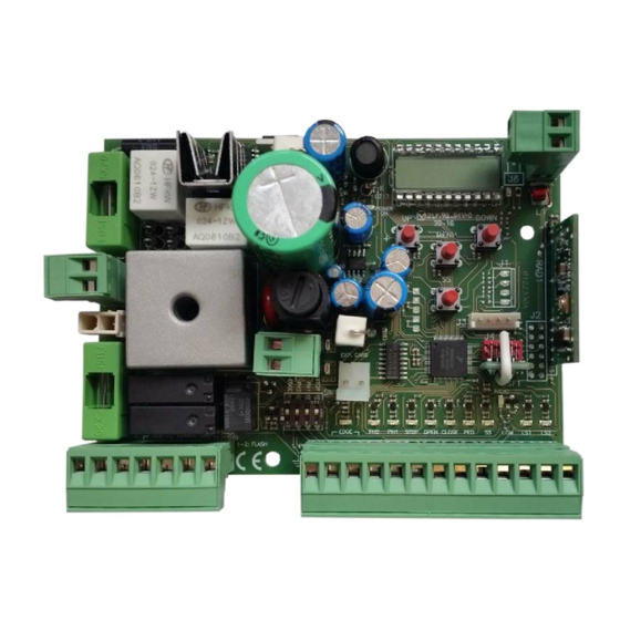
3 - PRODUCT DESCRIPTION The control unit BIOS1 24V is suitable for the installations of 1 motor with direct current 24V and a maximum absorption of 10A. This device has an easy and intuitive functioning thanks to the display interface and 4 buttons. The control unit allows a precise regulation of all parameters. The control unit can memorize up to 1000 transmitters (external memory) with the step by step, partial opening, open and close functions. -
Page 4: Preliminary Checks
3.2 - MODELS AND TECHNICAL FEATURES CODE DESCRIPTION 12006685 BIOS1 24V control unit for a single motor 60550058 Transformer 230 / 23 Vac 150VA 12006730 Bluetooth module 12000760 R1 card 12000780 Battery charger 24CBA card Transformer power supply 230Vac 50-60Hz... -
Page 5: Electrical Connections
to avoid the unintentional gate release. Note: Eliminate the mechanical stops of the kind described by Fig. 3. No mechanical stop shall be on top of the gate, since mechanical stops are not safe enough. Parts to install meeting the EN 12453 standard USE OF THE SHUTTER Skilled persons COMMAND TYPE... - Page 6 4.1 - LIST OF TERMINAL BOARDS AND CONNECTORS Number Name Description 1 - 2 FLASH Flashing light output at 24Vac. Use a flashing light without self flashing card 24Vac 25W max. 3 - 4 Courtesy light / Open automation light output at 24Vac. Use a light 24Vac 25W max. The functioning of the auxiliary light and its activation time are managed from advanced items FC.Y.
- Page 7 5 - DISPLAY AND STATES OF THE CONTROL UNIT DOWN MENU By pressing the “DOWN” button it is possible to read on the display the following parameters. DISPLAY DESCRIPTION State showing (--, OP, CL, ...) Description of the control unit state. Refer to the STATES OF THE CONTROL UNIT table for the description of the single states of functioning.
-
Page 8: Signalling Led
5.3 - MALFUNCTION SIGNALLINGS DISPLAY DESCRIPTION Memory error: the external memory not installed or not recognised. Memory error during the writing: the value x is a number from 1 to 6. In the event of the error, contact the technical assistance. DISPLAY Limit switches error: opening and closing limit switches are busy in the same time RELAY 4... - Page 9 The learning of a transmitter can be enabled with the “UP” button of the control unit or with the hidden key of a transmitter already memorized. The BIOS1 24V control unit can memorize up to 4 functions in as many keys of the remote control. During the learning procedure, described at DOWN paragraph 6.1, a single key is stored.
- Page 10 DOWN MENU 6.2 - LEARNING WITH THE HIDDEN KEY OF A TRANSMITTER ALREADY MEMORIZED DOWN MENU MENU DISPLAY Blinker With the automation steady, with the aid of a clip press the hidden key of a DOWN ...
- Page 11 7 - SETTING OF THE STROKE NOTE - check with the advanced menu de.f.(chapter 9) if the selected motor type is correct, before carring out the learning. At the first power up, it is necessary to carry out a learning of the stroke for the acquisition of the stroke length and the slowdowns. After this procedure the installation is complete.
- Page 12 7.2 - ADVANCED SETTINGS OF THE STROKE Be sure that the limit switches are connected and correctly adjusted. Carry out a check of the menus and, if needed, customize the settings before the learning of the stroke. Be sure to have set the item menu LSI = P. ...
- Page 13 8 - CHANGE PARAMETERS - BASIC MENU DOWN It is possible to access a BASIC MENU to change the main parameters of the control unit. DOWN MENU To enter the menu, proceed as described below. MENU WARNING - after 2 minutes of inactivity, the control unit exits automatically from the menu. ...
- Page 14 DEFAULT PARAMETERS DESCRIPTION UNIT CUSTOM Amplitude of slowdown. P = personalized during learning. 0…100% = percentage of stroke. Anti slipping / Extra time. NOTE - the parameters highlighted in grey depend on the selected motor. In the table are reported the data of the CUSTOM motor. For more information, refer to chapter 11.
- Page 15 9 - CHANGE PARAMETERS - ADVANCED MENU DOWN This menu allows a more detailed setting of some parameters. MENU To enter the ADVANCED MENU, press and hold the “MENU” button for at least 5 seconds. To change the parameters, proceed as described for the BASIC MENU. WARNING - after 2 minutes of inactivity, the control unit exits automatically from the menu.
- Page 16 DEFAULT PARAMETERS DESCRIPTION UNIT CUSTOM Threshold of cycles for assistance request. Once the limit is reached the x 1000 next cycles will be done with fast blinking (only if FPr enabled). cycles 0 = disabled. Continuous blinking for assistance request (done only with closed automation): 0 = disabled.
- Page 17 The opening photocell has the following functioning: • Opening: stops the movement and waits until the beam is freed, then moves in opening. • Closing: – ph.2. = 0 stops the movement and waits until the beam is freed, then moves in opening. –...
- Page 18 WARNING - Do not use with sliding gates. 23. MECHANICAL RELAXATION Mr.E. Function for the mechanical relaxation of the motor: it is useful on those motors that have the unlock for the manual movement which can remain locked due to the pressure of the motor on the mechanical stop. When it arrives on the mechanical stop, opening or closing, the motor will do a short inversion of Mr.E.
-
Page 19: Eco Mode
DOWN DOWN DOWN DOWN DOWN DOWN 10 - ECOMODE MENU MENU MENU MENU MENU MENU The ECOMODE function allows to increase the batteries life in the event of a black-out of the grid. To enable the function: ... -
Page 20: Default Values
11 - DEFAULT VALUES The BIOS1 24V control unit has the possibility to select the used motor. This allows to set, as defaults, some parameters for the optimal functioning of the motor. Here below, the table of the parameters with the default values assigned that depend on the motor.
Need help?
Do you have a question about the BIOS1 24V and is the answer not in the manual?
Questions and answers