
Related Manuals for Allmatic BIOS1 24 POWER


Summary of Contents for Allmatic BIOS1 24 POWER
- Page 1 BIOS1 24 POWER CONTROL UNIT FOR SLIDING GATES rev. firmware BIOS124P01 istr. 6-1622399 rev. 0 23/10/2020...
-
Page 2: General Warnings
2 - PRODUCT DESCRIPTION The control unit BIOS1 24 POWER is suitable for installations with a 24Vdc sliding motor. Its operation is easy and intuitive thanks to the display interface and the 4 buttons for menu navigation. The control panel allows precise adjustment of all parameters. The control unit can store up to 1000 transmitters (external memory) with the function step by step, partial opening, open and close. -
Page 3: Power Board
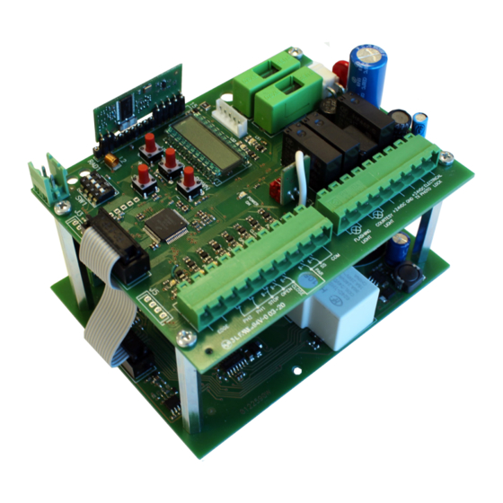
Fig. 2 POWER BOARD • M4: 24V motor output • F4: Fuse 30A for 24Vdc accessories protection • M5: 24V input for power supply • C: Cable connector for communication between power • CB: Battery charger connector (optional) board and control board 3 - PRELIMINARY CHECKS WARNINGS! Gate features must be uniformed with the standards and laws in force. -
Page 4: Command Type
3.1 - PARTS TO INSTALL MEETING THE EN 12453 STANDARD USE OF THE CLOSURE Qualified persons COMMAND TYPE Qualified persons (out of public Unrestricted use (public area) area*) with manned operation not possible with visible impulses C or E C or E C and D, or E (e.g. - Page 5 4 - SELECTION OF THE MOTOR WARNING! Before executing the learning of the strokes, the memorization of the transmitters and before performing any other setting, it is necessary to select the motorization in use, this allows to optimize the operation of BIOS1 24 POWER.
-
Page 6: Electrical Connections
5 - ELECTRICAL CONNECTIONS WARNING! Before making the connections, be sure that the control unit is not powered up. SECURITY DIP-SWITCH: Set to “ON” to disable inputs EDGE, PH2, PH1 and STOP. Eliminates the need to bridge the terminal board inputs WARNING - with the dip switch ON, the safety devices are disabled. - Page 7 NUMBER NAME DESCRIPTION EDGE Safety edge input (NC contact). Select the type of the used safety edge (mechanical or resistive) through the advanced menu EDM and the mode of intervention with the advanced menu ied. WARNING - with DIP EDGE on “ON” the input is disabled. 3-10 PH2 - COM Opening photocell input (NC contact).
- Page 8 NUMBER NAME DESCRIPTION SHIELD Connect the antenna shield. 22 - 23 MOTOR 24Vdc MOTOR power supply. +24 VDC +24Vdc “POWER BOARD” power supply. 0 VDC 0Vdc “POWER BOARD” power supply. 6 - REMOTE CONTROL LEARNING The learning of a transmitter can be enabled with the “UP” button of the control unit or with the hidden key of a transmitter already memorized.
- Page 9 6.2 - LEARNING WITH THE HIDDEN KEY OF A TRANSMITTER ALREADY MEMORIZED With stationary automation it is possible to press the hidden button of an already learned transmitter to open the radio memory of the control unit. This is equivalent to pressing the «UP» button on the control unit. Then follow the learning procedure from point 3 to 5 of the previous paragraph.
- Page 10 7.1 - EASY SETTINGS OF THE STROKE With the simple learning the control unit autonomously performs all the procedure and calculation of slowdowns, which will be set with the same percentage both in opening and closing (base parameter LSI). Before starting the procedure make sure you have installed the electric limit switches and have them properly adjusted.
- Page 11 7.2 - ADVANCED SETTINGS OF THE STROKE With personalized learning, the slowdowns will have to be set during the learning procedure and the amplitudes in the two direc- tions will be independent. Before starting the procedure make sure you have installed the electric limit switches and have them properly adjusted.
- Page 12 8 - PROGRAMMING OF THE CONTROL UNIT 8.1 - DISPLAY By pressing the “DOWN” button it is possible to read on the display the following parameters. DISPLAY DESCRIPTION State showing (--, OP, CL, ...) Description of the control unit state. Refer to the follow table for the description of the single states of functioning.
- Page 13 8.3 - DISPLAY SIGNALLINGS DURING THE FUNCTIONING DISPLAY DESCRIPTION Visualized during the learning of transmitters. Visualized when a new transmitter is memorized or at the end of a reset. Visualized when a key of a transmitter already memorized is stored. Visualized when a trasmitter is erased.
- Page 14 8.5 - CHANGE PARAMETERS - BASE MENU It is possible to access to the BASE MENU to change the main parameters of the control unit. To enter the menu, proceed as described below. WARNING - after 2 minutes of inactivity the control unit automatically exits from the menu. Example of accessing the base menu to modify the tCL parameter.
- Page 15 DEFAULT KALOS PARAMETERS DESCRIPTION XL 24 POWER Running speed. Slowdowns speed. Step-by-Step configuration: 0 = normal (AP-ST-CH-ST-AP-ST…). 1 = alternated STOP (AP-ST-CH-AP-ST-CH…). 2 = alternated (AP-CH-AP-CH…). 3 = condominium - timer. 4 = condominium with immediate auto reclosing. Behavior after the blackout: 0 = no action.
- Page 16 adjustment of this parameter it is recommended to perform a complete movimentation (opening and closing) before trying the obstacle detection. Lower values correspond to a greater thrust on the obstacle. The intervention for obstacle stops the automation and makes a short inversion of the movement. 5.
- Page 17 8.6 - CHANGE PARAMETERS - ADVANCE MENU This menu allows a more detailed setting of some parameters. To enter the ADVANCED MENU, press and hold the “MENU” button for at least 5 seconds. To change the parameters, proceed as described for the BASIC MENU. WARNING - after 2 minutes of inactivity, the control unit exits automatically from the menu.
- Page 18 DEFAULT KALOS PARAMETERS DESCRIPTION XL 24 POWER Safety edge test: 0 = disabled. 1 = enabled. Partial opening. Auto reclosing time from partial opening (0 = disabled). Blinker output mode: 0 = fix. 1 = blinking. Pre-flashing time (0 = disabled). Courtesy light settings: 0 = at the end of the movement, light ON for a TCY time.
- Page 19 DEFAULT KALOS PARAMETERS DESCRIPTION XL 24 POWER Cancelling all transmitters. Enter to modify the parameter and then keep pressed the “MENU” button, a count down appears that ends with don on the display. Not in use. : WARNING - do not use on the sliding motors. : These values are not suggested for the sliding motors.
- Page 20 8. PHOTOCELLS TEST TPh By enabling this function, before each movement starting from steady automation, the control unit does a functional check of the photocells. The check will not be done in case of fast movement after the intervention of a safety device. Follow paragraph 5 for the connections of the photocells.
- Page 21 – Opened: light on. – Closed: light off. – Stopped: 2flash + long wait + 2flash + long wait + … 19. COURTESY LIGHT TIME tCY Activation time of the courtesy light. 20. DEAD-MAN MODE DEA During the DEAD MAN functioning mode the automation moves only with a permanent command. The enabled commands are OPEN and CLOSE.
-
Page 22: Parameter Sid
29. VIEWING OF THE MEMORY POSITION FOR A SINGLE TRANSMITTER TRS With the item of the menu trS it is possible to view the memory location in which a transmitter is memorized. To perform the function, move to trS and then confirm by pressing the “MENU” button. Keep pressed the “MENU” button untill the display will show SEE, then release the button. - Page 23 8.7 - DEFAULT VALUES The BIOS1 24V POWER control unit has the possibility to select the used motor. This allows to set, as defaults, some parameters for the optimal functioning of the motor. Here below, the table of the parameters with the default values assigned that depend on the motor.. DEFAULT VALUES MENU DISPLAY...
- Page 24 9 - MALFUNCTION SIGNALLINGS DISPLAY DESCRIPTION Memory error: the external memory not installed or not recognised. Memory error during the writing: the value x is a number from 1 to 6. In the event of the error, contact the technical assistance. Limit switches error: opening and closing limit switches are busy in the same time.
-
Page 25: Disposal Of The Product
10 - DISPOSAL OF THE PRODUCT This product is an integral part of the automation, and therefore, they must be disposed of together. As for the installation operations, at the end of the life of this product, the dismantling operations must be performed by qualified personnel. This product is made from different types of materials: some can be recycled, others must be disposed of. - Page 26 NOTE 26 / 28 firmware BIOS124P01 6-1622399 rev. 0...
- Page 27 NOTE 6-1622399 rev. 0 firmware BIOS124P01 27 / 28...
- Page 28 ALLMATIC S.r.l 32026 Borgo Valbelluna - Belluno – Italy Via dell’Artigiano, n°1 – Z.A. Tel. 0437 751175 – 751163 r.a. Fax 0437 751065 www.allmatic.com - E-mail: info@allmatic.com...
Need help?
Do you have a question about the BIOS1 24 POWER and is the answer not in the manual?
Questions and answers