Allmatic BIOS2 Manual For Installation
Programmable control board for wings gates
Hide thumbs
Also See for BIOS2:
- Manual for installation (49 pages) ,
- Manual for installation (48 pages)

Related Manuals for Allmatic BIOS2


Summary of Contents for Allmatic BIOS2
- Page 1 CONTROL UNIT BIOS2 Programmable Control board for wings gates www.remotecontrolgates.co.uk Manual for installation...
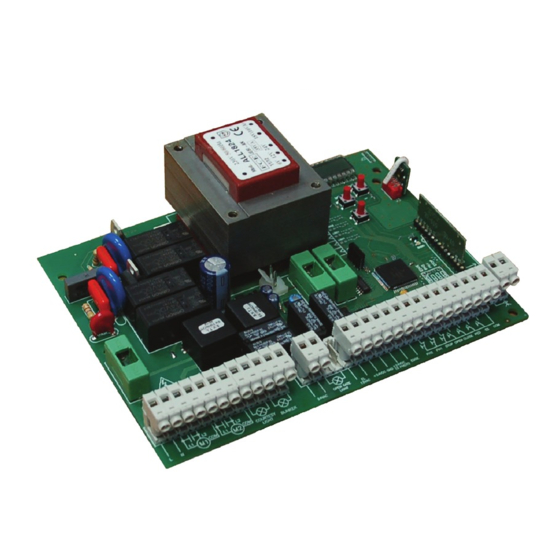
- Page 2 1. Introduzione The control unit BIOS2 is particularly indicated for the installation of 1 or 2 wing gates with 230 Vac motors with maximum power absorbed of 700W.The control unit equipped with a display that allows a precise regulation of the thrust of the gates and sensitivity. It is also possible to adjust the delay in closure of the second wing in the base settings menu.
- Page 3 COURTESY LIGHT OUTPUT It is possible to light up the action area of the Connect the courtesy light to the clamps 9 and automatism during each motion. 10, 230Vac 100W MAX. The functioning of the auxiliary light is controlled in the advanced menu .
- Page 4 4. Remote control learning 4. Remote control learning 4.1 Learning of one transmitter The 1st memorized key performs the STEP by STEP function (opening and closing of the gate), the 2 key performs the pedestrian opening, the 3 key performs the OPEN function, 4 key performs the CLOSE function.
- Page 5 For a correct functioning of the system, it is absolutely indispensable the use of mechanical stops in opening and closing. 5.2 Advanced settings of the wings stroke (parameter = ) Connect to the MOTOR 1 output the wing which beats.Install an aventual electrical lock on this wing. MOTOR 1 is always activated first during opening phase and in second during closing phase.
- Page 6 6. Menu Ex. Base menu Entering the menu: To enter the base menu settings keep pressed the MENU button for at least one second To enter the advanced menu settings keep pressed the MENU button for at least five seconds Ex.
-
Page 7: Advanced Menu
6.2 Advanced menu: SELECTABLE MENU DESCRIPTION VALUES DEFAULT UNITS min-max Functioning of opening photocell PHOTO2 0 = Enabled in opening and closing OP/CL 1 = Enabled only in opening OP Photocells test 0 = disabled ... - Page 8 6.3 Menu description: 6.3.1 Base settings menu Auto reclosing time Active when the gate is in the completely open position, the gate automatically closes after seconds. In this phase the display shows with the blinking dash, that during the last 10 seconds will be replaced by the count down. Auto reclosing time after transit If in the opening phase or in the completely open position the beam of the photocells is obscured and freed, the gate automatically closes after ...
- Page 9 6.3.2 Advanced menu .. Bluetooth Item of the menu needed to the first coupling between an Android device and the control unit. Refer to the Help of the Android application for the connection procedure. .. Electrical brake Short reverse movement with reduced torque to reduce the inertia of the gate. The operation is performed at each stop of the movement except for fast movement after the intervention of a safety devices.
- Page 10 .. Dead man During dead man functioning mode the gate moves only with a permanent command. The enabled commands are OPEN and CLOSE. SS and PED are disabled. During dead man functioning all the automatic movements are disabled, like short or total inversions. All safety devices are disabled except for STOP. ..
-
Page 11: Normal Functioning
7. Display and control unit state 7.1 Normal functioning: Standby - Gate closed or after the switch on of the control unit Opening phase Closing phase Gate closed by user during opening Gate closed by user during closing Gate stopped by an external event (photocells, stop) Gate opened without automatic reclosing Gate opened in pedestrian position without automatic reclosing Gate opened waiting for auto reclosing, last 10 seconds the dash will be replaced by the countdown... -
Page 12: Technical Features
7.3 Input LED and safety devices 8. Technical features POWER SUPPLY AND CONSUMPTION Power supply voltage 230 Vac - 50/60 Hz Absorption from line (Standby) 55mA @ 230 Vac Standard configuration (2 couple of photocells, RX radio safety edge) Line fuse F6.3A MOTOR POWER SUPPLY Number of motors...
Need help?
Do you have a question about the BIOS2 and is the answer not in the manual?
Questions and answers