Lenze 9300 vector Information For The Operator Of The Machine
Hide thumbs
Also See for 9300 vector:
- System manual (466 pages) ,
- Manual (41 pages) ,
- Important notes (6 pages)

Related Manuals for Lenze 9300 vector


Summary of Contents for Lenze 9300 vector
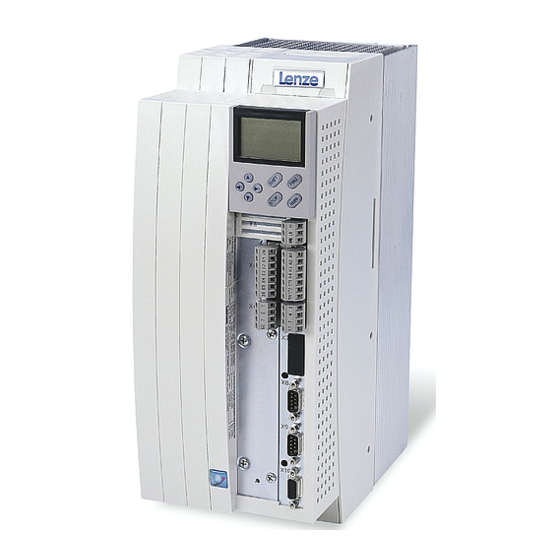
- Page 1 - Lenze EDKVF93−05 .6v_ Information for the operator of the machine 9300 vector 250 ... 400 kW EVF9381 ... EVF9383 Frequency inverter...
- Page 2 - Lenze This documentation is valid for ..9300 vector frequency inverters as of nameplate data: ‚ ƒ Nameplate Type 93xx ˘ V Vxx 1x 7x 93xx ˘ V Vxx Vx 6x Product series EVF = Frequency inverter...
- Page 3 Note! This documentation contains all the information required by the machine operator to run the drive controllers of the 9300 vector series installed in your machine/system. You may make further use of the information contained in this documentation without asking Lenze for permission if you do not change the contents.
- Page 4 - Lenze L1 L2 L3 BR1 BR2 L1 L2 L3 PE BR1 BR2 U, V, W U, V, W BR1, BR2 BR1, BR2 +UG, -UG +UG, -UG L1, L2, L3, PE L1, L2, L3, PE 9300vec0181...
- Page 5 - Lenze Key for overview Position Description 9300 vector frequency inverter − master 9300 vector frequency inverter − slave Connections and interfaces Position Description L1, L2, L3, PE Mains connection +UG, −UG DC supply (only for the variants V210, V240, V270, V300)
-
Page 6: Table Of Contents
............General safety and application instructions for Lenze controllers . -
Page 7: Safety Instructions
(According to: Low−Voltage Directive 73/23/EEC) For you personal safety Lenze controllers (frequency inverters, servo inverters, DC speed controllers) and the accessory components can include live and rotating parts − depending on their type of protection − during operation. Surfaces can be hot. - Page 8 Reduce housing openings and cutouts to a minimum. Lenze controllers can cause a DC current in the protective conductor. If a residual current device (RCD) is used as a protective means in the case of direct or indirect contact, only a residual current device (RCD) of type B may be used on the current supply side of the controller.
- Page 9 - Lenze Safety instructions General safety and application instructions for Lenze controllers Operation If necessary, systems including controllers must be equipped with additional monitoring and protection devices according to the valid safety regulations (e.g. law on technical equipment, regulations for the prevention of accidents). The controller can be adapted to your application.
-
Page 10: Residual Hazards
- Lenze Safety instructions Residual hazards Residual hazards Protection of persons Before working on the controller, check that no voltage is applied to the power ƒ terminals: – The power terminals U, V, W, +U , −U , BR1, BR2 and 101 ... 104 remain live for at least five minutes after disconnecting the mains. -
Page 11: Definition Of Notes Used
- Lenze Safety instructions Definition of notes used Definition of notes used The following pictographs and signal words are used in this documentation to indicate dangers and important information: Safety instructions Structure of safety instructions: Danger! (characterises the type and severity of danger) -
Page 12: Parameter Setting
- Lenze Parameter setting Parameter setting with the XT EMZ9371BC keypad General data and operating conditions Parameter setting Parameter setting with the XT EMZ9371BC keypad Description The keypad is available as an accessory. A full description of the keypad can be obtained from the Instructions included in the keypad delivery. -
Page 13: Installation And Commissioning
- Lenze Parameter setting Parameter setting with the XT EMZ9371BC keypad Installation and commissioning 2.1.2 Installation and commissioning SHPRG Menu 0050 Code Para 50.00_Hz M C T R L - N O U T EMZ9371BC ‚ E82ZBBXC SHPRG... - Page 14 - Lenze Parameter setting Parameter setting with the XT EMZ9371BC keypad Display elements and function keys Displays Display Meaning Explanation 0 Status displays of standard device Ready for operation Pulse inhibit is active Power outputs are inhibited Set current limit is exceeded in motor or...
-
Page 15: Changing And Saving Parameters
- Lenze Parameter setting Parameter setting with the XT EMZ9371BC keypad Changing and saving parameters Function keys Note! Key combinations with T: Press T and keep it pressed, then press the second key in addition. Function Menu level Code level... - Page 16 Display of C0003 "PAR SAVE" 13. Set parameters for another parameter Restart the "loop" with step 1. or 3. The function of the S key can be programmed: C0469 = 1: Controller inhibit C0469 = 2: Quick stop (Lenze setting) EDKVF93−05 EN 1.0...
-
Page 17: Loading A Parameter Set
- Lenze Parameter setting Parameter setting with the XT EMZ9371BC keypad Loading a parameter set 2.1.5 Loading a parameter set The keypad serves to load a saved parameter set into the main memory when the controller is inhibited. After the controller is enabled, it operates with the new parameters. -
Page 18: Transfering Parameters To Other Standard Devices
- Lenze Parameter setting Parameter setting with the XT EMZ9371BC keypad Transfering parameters to other standard devices 2.1.6 Transfering parameters to other standard devices The keypad enables you to copy parameter settings from one standard device to another. For this purpose use the "Load/Store" menu:... - Page 19 - Lenze Parameter setting Parameter setting with the XT EMZ9371BC keypad Transfering parameters to other standard devices Copying parameter sets from the keypad to the standard device Step Action sequence Connect keypad to controller 2 Inhibit controller Terminal X5/28 = LOW The "IMP"...
-
Page 20: Activating Password Protection
- Lenze Parameter setting Parameter setting with the XT EMZ9371BC keypad Activating password protection 2.1.7 Activating password protection Note! If the password protection is activated (C0094 = 1 ... 9999), you only have ƒ free access to the user menu. -
Page 21: Diagnostics
- Lenze Parameter setting Parameter setting with the XT EMZ9371BC keypad Diagnostics 2.1.8 Diagnostics The two submenus "Actual info" and "History" in the "Diagnostic" menu contain all codes for the monitoring of the drive ƒ error diagnosis ƒ Status messages are additionally displayed in the operating level. If several status... -
Page 22: Menu Structure
- Lenze Parameter setting Parameter setting with the XT EMZ9371BC keypad Menu structure 2.1.9 Menu structure For simple, user−friendly operation, the codes are clearly arranged in function−related menus: Main menu Submenus Description Display Display User−Menu Codes defined in C0517... - Page 23 - Lenze Parameter setting Parameter setting with the XT EMZ9371BC keypad Menu structure Main menu Submenus Description Description Display Display LECOM/AIF Configuration of operation with communication modules LECOM A/B Serial interface AIF interface Process data Status word Display of status words...
-
Page 24: Troubleshooting And Fault Elimination
- Lenze Troubleshooting and fault elimination Display of operating data, diagnostics Display of operating data Troubleshooting and fault elimination Display of operating data, diagnostics 3.1.1 Display of operating data Description Important operating parameters are measured by the controller. They can be displayed with the keypad or PC. -
Page 25: Diagnostics
- Lenze Troubleshooting and fault elimination Display of operating data, diagnostics Diagnostics Code Possible settings IMPORTANT Name Lenze Selection C0064 Utilization {1 %} 150 Device utilisation I×t Read only Device utilisation during the last 180 s of operating time C0064 >... -
Page 26: Troubleshooting
- Lenze Troubleshooting and fault elimination Troubleshooting Status display (LEDs on the controller) Troubleshooting Detecting failures The controller LEDs and the status information displayed on the keypad immediately indicate errors or operation problems. Analysing errors You can analyse an error using the history buffer. The Error messages" list helps you to eliminate the error. -
Page 27: Fault Analysis With The History Buffer
- Lenze Troubleshooting and fault elimination Troubleshooting Fault analysis with the history buffer 3.2.2 Fault analysis with the history buffer Retracing faults Faults can be retraced via the history buffer. Fault messages are stored in the 8 memory locations in the order of their appearance. -
Page 28: Drive Behaviour In The Event Of Faults
- Lenze Troubleshooting and fault elimination Drive behaviour in the event of faults Fault analysis with the history buffer Drive behaviour in the event of faults The controller reacts in different ways to the three possible types of fault (TRIP, message... -
Page 29: Error Elimination
– The motor rotates faster than the speed setpoint by the value set in C0074 (influence of the speed controller, Lenze setting 10 % of n ). After the controller is enabled, it does not stop at zero speed setpoint or quick stop (QSP). -
Page 30: Controller In Clamp Operation
- Lenze Troubleshooting and fault elimination Error elimination Controller in clamp operation 3.4.2 Controller in clamp operation The clamp operation is a permissible operating mode. But since, however, pulse inhibit is set again and again, the controller cannot provide the optimum power. Moreover, the fault OC3 (TRIP) can be activated. - Page 31 - Lenze Troubleshooting and fault elimination Error elimination Controller in clamp operation If the DC−bus voltage (U ) exceeds the switch−off threshold OU, pulse inhibit will be set. At the same time, an internal timer for a delay time (C0912) will be started.
- Page 32 OU is lower than the delay time set in C0912. The pulse inhibit is deactivated after the delay time in C0912 has elapsed. In C0912 the delay time is set in [ms].The Lenze setting can be changed by the factor ƒ...
-
Page 33: Fault Messages On The Keypad Or In The Parameter Setting Program Global Drive Control
- Lenze Troubleshooting and fault elimination Error elimination Fault messages on the keypad or in the parameter setting program Global Drive Control 3.4.3 Fault messages on the keypad or in the parameter setting program Global Drive Control Note! If you use GDC or a fieldbus module to retrieve the fault (C0168/x), the error message will be represented by an error number. - Page 34 - Lenze Troubleshooting and fault elimination Error elimination Fault messages on the keypad or in the parameter setting program Global Drive Control Display Error number Error Cause Remedy x = 0: TRIP x = 1: Message x = 2: Warning x110 Sensor fault −...
- Page 35 For this test the function block DFIN must be entered into the processing table. In the Lenze setting, DFIN is entered at position 1 of the processing table (C0465/1 = 200). – Deactivate feedback with C0025 = 1 –...
- Page 36 Correct parameter set parameters saved do not match the Save all parameter sets with C0003 software version of the controller. and reset the fault message by mains CAUTION! The Lenze setting is loaded switching automatically. x072 Parameter set error Fault while loading a parameter set...
- Page 37 - Lenze Troubleshooting and fault elimination Error elimination Fault messages on the keypad or in the parameter setting program Global Drive Control Display Error number Error Cause Remedy x = 0: TRIP x = 1: Message x = 2: Warning...
-
Page 38: Resetting Error Messages
- Lenze Troubleshooting and fault elimination Resetting error messages Fault messages on the keypad or in the parameter setting program Global Drive Control Resetting error messages Eliminate the cause of TRIP fault message After you have eliminated the cause of a TRIP fault message, you must reset the fault message with the command "TRIP reset". - Page 39 - Lenze Troubleshooting and fault elimination Resetting error messages Fault messages on the keypad or in the parameter setting program Global Drive Control EDKVF93−05 EN 1.0...
- Page 40 - Lenze Lenze Drive Systems GmbH EDKVF93−05 Hans−Lenze−Straße 1 EN 1.0 D−31855 Aerzen © 08/2007 Germany TD19 +49 (0) 51 54 82−0 Service 00 80 00 24 4 68 77 (24 h helpline) Ê Service +49 (0) 51 54 82−1112 E−Mail...
Need help?
Do you have a question about the 9300 vector and is the answer not in the manual?
Questions and answers