Lenze L-force 9400 Mounting Instructions
1.5 ... 23.5 a. single drive highline/stateline
Hide thumbs
Also See for L-force 9400:
- Hardware manual (646 pages) ,
- Mounting instructions (206 pages) ,
- Manual (139 pages)
Table of Contents
Advertisement
Quick Links
Download this manual
See also:
Manual
Advertisement
Table of Contents

Subscribe to Our Youtube Channel
Related Manuals for Lenze L-force 9400


Summary of Contents for Lenze L-force 9400
- Page 1 EDK94ASH24 L−force Drives .P!õ Mounting Instructions 9400 1.5 ... 23.5 A E94ASHExxxx Single Drive HighLine/StateLine Axis module...
- Page 2 Please read these instructions before you start working! Follow the enclosed safety instructions.
- Page 3 9400SSP012...
- Page 4 EN 61800−5−1 HighLine StateLine þ X100 þ X105 þ X106 X107 X109 X110 − 1x 7 II + III), © 2014 Lenze Automation GmbH, Postfach 10 13 52, D−31763 Hameln, Hans−Lenze−Str. 1, D−31855 Aerzen Lenze Automation GmbH EDK94ASH24 ZH/EN 4.1...
- Page 5 Lenze UL UR EDK94ASH24 ZH/EN 4.1...
- Page 6 à à à à à à – – – à http://www.Lenze.com EDK94ASH24 ZH/EN 4.1...
- Page 7 Lenze Lenze 2006/95/EG 364/CENELEC HD 384 DIN VDE 0100 IEC report 664 DIN VDE 0110 EN 61000−3−2 98/37/EC EN 60204 (2004/108/EC) 2006/95/EC EN 61800−5−1 EN 61800−3 EDK94ASH24 ZH/EN 4.1...
- Page 8 Lenze VBG 4 (RCD) (RCD) 98/37/EC 1.2.7 IEC 61508 EN 954−1 EN 1037 EDK94ASH24 ZH/EN 4.1...
- Page 9 ƒ – U V W +UG −UG Rb1 3 ... 20 – L1 L2 L3 U V W +UG −UG Rb1 ƒ ƒ ƒ – ƒ – – ƒ – EDK94ASH24 ZH/EN 4.1...
- Page 10 EDK94ASH24 ZH/EN 4.1...
- Page 11 Branch circuit protection: ƒ Suitable for use on a circuit capable of delivering not more than 5000 rms symmetrical amperes, 500 V max. Voltage of the fuses must at least be suitable with the input voltage of the ƒ drive. The integral solid state protection does not provide branch circuit ƒ...
- Page 12 EN 61800−3 10 m: EN 61800−3 2006/95/EC UL 508C 132659 GOST−R 51321.1−2000 POCC DE.AN30.B08815 51321.3−99 EN 60529 IP 20 NEMA 250 EN 61800−5−1 2000 m EN 61800−5−1 300 V EN 61800−5−1 − EN 61800−5−1 > 3.5 mA AC, > 10 mA DC EDK94ASH24 ZH/EN 4.1...
- Page 13 ° IEC/EN 60721−3−1 1K3 (−25 ... +60 ° IEC/EN 60721−3−2 2K3 (−25 ... +70 ° IEC/EN 60721−3−3 3K3 (−10 ... +55 ° +45 ... +55 ° 1 ... 7 2.5 %/ ° 8S ... 10 1 %/ 0 ... 4000 m 1000 ...
- Page 14 f [Hz] 3/PE AC 180 − 0 % ... 264 + 0 % 45 ... 65 3/PE AC 320 − 0 % ... 440 + 0 % 45 ... 65 3/PE AC 400 − 0 % ... 550 + 0 % 45 ...
- Page 15 ° ° [Hz] E94ASxE0024 0 − 230/400/500 0 − 599 1.5/1.5/1.3 1.1/1.1/1.0 E94ASxE0034 0 − 230/400/500 0 − 599 2.5/2.5/2.2 1.9/1.9/1.7 E94ASxE0044 0 − 230/400/500 0 − 599 4.0/4.0/3.5 3.0/3.0/2.6 E94ASxE0074 0 − 230/400/500 0 − 599 7.0/7.0/6.1 5.3/5.3/4.6 E94ASxE0134 0 −...
- Page 16 SSP94GGmSo000 3−1 [mm] [mm] [kg] E94ASxE0024 E94ASxE0034 E94ASxE0044 E94ASxE0074 E94ASxE0134 E94ASxE0174 E94ASxE0244 EDK94ASH24 ZH/EN 4.1...
- Page 17 F1...F3 E94AZPxxxxx X100 ƒ E94ASxExxxx . . . X106 X105 X107 U V W ‚ EYF... SSP94PSP01 E94ASxExxxx 9400 E94AZPxxxxx F1 ... F4 /RFI " EYF... 1 (−10 ... 0 ... +10 V) ‚ ƒ 24 V IEC 61131−2 EDK94ASH24 ZH/EN 4.1...
- Page 18 EDK94ASH24 ZH/EN 4.1...
- Page 19 SSP94GG102 6−1 EDK94ASH24 ZH/EN 4.1...
- Page 20 ƒ ƒ ƒ ( , UL) ƒ ƒ – – – > 70 % 90°. – ƒ ƒ ƒ ƒ 24 V ƒ ƒ L−force »Engineer« EDK94ASH24 ZH/EN 4.1...
- Page 21 Pin 2 CAN−LOW Pin 3 CAN−GND Pin 7 CAN−HIGH 9400SSP000X1 CAN−Shield "StateLine" 24 V 24 V (SELV/PELV) ( 9400SSP000X2 in/out ( [AWG] [Nm] [lb−in] 0.2 ... 2.5 24 ... 12 EDK94ASH24 ZH/EN 4.1...
- Page 22 A1− 1 − A1− 1 − ±20mA A2− 2 − " SSP94000X3 [AWG] [Nm] [lb−in] 0.2 ... 2.5 24 ... 12 "StateLine" A1− 1 − A1− 1 − ±20mA " SSP94SL0X3 EDK94ASH24 ZH/EN 4.1...
- Page 23 24−V 9400SSP000X4 [AWG] [Nm] [lb−in] 0.2 ... 2.5 24 ... 12 "StateLine" 24−V 9400SSPxxx 9400SSP000X5 [AWG] [Nm] [lb−in] 0.2 ... 2.5 24 ... 12 "StateLine" EDK94ASH24 ZH/EN 4.1...
- Page 24 9400SSPxxx , RJ69 9400SSP000X6 +REF −REF +COS −COS +SIN −SIN +KTY 9400SSP000X7 −KTY EYF001... EYF002... − Hiperface EnDat 2.1 − − +RS485 Data (Z) Data + n. c. n. c. n. c. n. c. n. c. −KTY −KTY −KTY −KTY −...
- Page 25 þ MXI1 þMXI2 oMMI oMSI. E894YCEN001A 8−1 E94AYCEN X215 , RJ45 EN 50173 EDK94ASH24 ZH/EN 4.1...
- Page 26 CANopen E94YCCA001B 8−2 E94AYCCA (CANopen) X220 : Sub−D , 9− X220 Pin 2 CAN−LOW Pin 3 CAN−GND Pin 7 CAN−HIGH 9400SSP000X1 CAN−Shield EDK94ASH24 ZH/EN 4.1...
- Page 27 Baud CAN Address 9400CAN003 8−3 "1" ... "64") ƒ "a" ... "d") ƒ "OFF" C00350 ( ) C00351 ( 10kbit/s 20kbit/s 50kbit/s 125kBit/s 250kbit/s 500kbit/s 800kbit/s 1000kbit/s CANopen ("Z") DR303−3 CANopen ("F") EDK94ASH24 ZH/EN 4.1...
- Page 28 PROFIBUS E94YCPM001A 8−4 E94AYCPM (PROFIBUS) X200 , 2− X201 PROFIBUS : Sub−D , 9− X200 24 V (SELV/PELV) 24 V DC 20.4 − 0 % ... 28.8 V + 0 %, 200 mA − SSP94KP200 − − RxD/TxD−P M5V2 P5V2 5 V DC / 30 mA −...
- Page 29 : 1 126 S1 − S7 OFF ( ƒ C00899 S1 − S7 ƒ «64» «32» «16» «8» «4» «2» «1» (= 23) PROFIBUS EDK94ASH24 ZH/EN 4.1...
- Page 30 þ MXI1 þMXI2 oMMI oMSI. E94AYFLF004 , 9− Sub−D , 9− Sub−D +5 V 5 ... 9 V − SUBD09010 EDK94ASH24 ZH/EN 4.1...
- Page 31 +5 V ±6 % − SUBD09010 EDK94ASH24 ZH/EN 4.1...
- Page 32 o MXI1 oMXI2 þMMI oMSI. MM1xx MM1xx 1 MB ƒ SSP94M0001 8−5 E94AYM1x − − MM2xx / MM3xx / MM4xx MM2xx 1 MB ƒ (CAN) ƒ MM3xx 4 MB ƒ (CAN) ƒ MM4xx 8 MB ƒ 128 kB RAM ( ƒ...
- Page 33 SSP94M1001 8−6 Memory module with DIP switch (as of order designation E94AYM22) Baud CAN Address 9400CAN003 8−7 "1" ... "64") ƒ "a" ... "d") ƒ "OFF" C00350 ( ) C00351 ( 10kbit/s 20kbit/s 50kbit/s 125kBit/s 250kbit/s 500kbit/s 800kbit/s 1000kbit/s EDK94ASH24 ZH/EN 4.1...
- Page 34 o MXI1 oMXI2 oMMI þMSI. ƒ ƒ SM100, SM301 SSP94SM011 8−8 E94AYAA − − EDK94ASH24 ZH/EN 4.1...
- Page 35 SM100 (Safe torque off) ƒ safe standstill, SSP94SM112 8−9 E94AYAB SI1/SI2 GND 24 V " [AWG] [Nm] [lb−in] 0.2 ... 2.5 24 ... 12 0.2 ... 1.5 24 ... 16 0.5 ... 1.0 20 ... 18 " " EDK94ASH24 ZH/EN 4.1...
- Page 36 SM301 (STO) ƒ 1 (SS1) ƒ 2 (SS2) − IEC 61800−5−2 ƒ (SSE) ƒ (SOS) − EN 61800−5−2 SOS ƒ (SMS) ƒ 1 (SLS1) ƒ (OMS) ƒ (ES) ƒ (SSM) ƒ ƒ ƒ ƒ (PROFIsafe V1) ƒ SM301 V1.1 2 (SLS2) ƒ...
- Page 37 SSP94SM321 X82.1 X82.2 X82.3 X82.4 SM301 0 ... 1023 24 V VA 1.xx SM301 (C15111) ƒ ƒ EDK94ASH24 ZH/EN 4.1...
- Page 38 X82.1 GND SD−Out1 SD−Out1 SD−Out1 X82.2 − +24 V (SELV/PELV) GND 24O SD−Out1 (SELV/PELV) +24 V X82.3 GND SD−In2 SD−In2 SD−In2 GND SD−In1 SD−In1 SD−In1 1− X82.4/AIS EDK94ASH24 ZH/EN 4.1...
- Page 39 X82.4 GND SD−In4 SD−In4 SD−In4 GND SD−In3 SD−In3 SD−In3 1− X82.3/AIS [Nm] [lb−in] 0.25 ... 0.75 24 ... 18 0.14 ... 1.5 26 ... 16 9 mm "STO" SS1/STO SS2/SOS 0.1/0.9 EDK94ASH24 ZH/EN 4.1...
- Page 40 EZAEBK0001 ƒ ® Windows 2000) ƒ »Engineer« ƒ ƒ – – (CANopen) – ƒ ƒ 24 V ƒ EDK94ASH24 ZH/EN 4.1...
- Page 41 EDK94ASH24 ZH/EN 4.1...
- Page 42 3 or 2 © 2014 Lenze Automation GmbH, Postfach 10 13 52, D−31763 Hameln, Hans−Lenze−Str. 1, D−31855 Aerzen No part of this documentation may be reproduced or made accessible to third parties without written consent by Lenze Automa- tion GmbH.
-
Page 43: Table Of Contents
Contents Quick start guide Safety instructions General safety and application notes for Lenze controllers Residual hazards Notes used Safety instructions for the installation according to UL or UR Technical data General data and operating conditions Electrical data Dimensions Example circuit... -
Page 44: Quick Start Guide
– Adjust the memory modules. – Wire the safety modules. 7. Final works from page 79 Tip! Documentation and software updates for further Lenze products can be found on the Internet in the "Services & Downloads" area under http://www.Lenze.com EDK94ASH24 ZH/EN 4.1... -
Page 45: Safety Instructions
General safety and application notes for Lenze controllers (in accordance with Low−Voltage Directive 2006/95/EC) General Lenze controllers (frequency inverters, servo inverters, DC controllers) and the accessory components can include live and rotating parts − depending on their type of protection − during operation. Surfaces can be hot. - Page 46 Reduce housing openings and cutouts to a minimum. Lenze controllers can cause a direct current in the protective conductor. If a residual current device (RCD) is used as a protective means in the case of direct or indirect contact, only a residual current device (RCD) of type B may be used on the current supply side of the controller.
- Page 47 Safety instructions General safety and application notes for Lenze controllers Safety functions Special controller variants support safety functions (e.g. "safe torque off", previously "safe standstill") according to the requirements of Annex I No. 1.2.7 of the EC Directive "Machinery" 98/37/EC, IEC 61508, EN 954−1 and EN 1037. Strictly observe the notes on the safety functions given in the documentation for the respective variants.
-
Page 48: Residual Hazards
Safety instructions Residual hazards Residual hazards Protection of persons Before working on the controller, check that no voltage is applied to the power ƒ terminals, because – depending on the controller − the power terminals U, V, W, +UG, −UG, Rb1 and Rb2 carry hazardous voltages for up to 3 to 20 minutes after mains disconnection. -
Page 49: Notes Used
Safety instructions Notes used Notes used The following pictographs and signal words are used in this documentation to indicate dangers and important information: Safety instructions Structure of safety instructions: Danger! (characterises the type and severity of danger) Note (describes the danger and gives information about how to prevent dangerous situations) Pictograph and signal word Meaning... -
Page 50: Safety Instructions For The Installation According To Ul Or Ur
Safety instructions Safety instructions for the installation according to U or U Safety instructions for the installation according to U or U Warnings! Branch circuit protection: ƒ Suitable for use on a circuit capable of delivering not more than 5000 rms symmetrical amperes, 500 V max. -
Page 51: Technical Data
Technical data General data and operating conditions Technical data General data and operating conditions Supply system data Supply forms With earthed neutral Unrestricted use IT systems Observe instructions about special measures! Noise emission EN 61800−3 Cable−guided, up to 10 m motor cable length: category C2 Radiation: category C3 Noise immunity EN 61800−3... - Page 52 Technical data General data and operating conditions Environmental conditions Climate Storage IEC/EN 60721−3−1 1K3 (−25 ... +60 °C) Transport IEC/EN 60721−3−2 2K3 (−25 ... +70 °C) Operation IEC/EN 60721−3−3 3K3 (−10 ... +55 °C) Current derating at +45 ... +55 °C: Device size 1 ...
-
Page 53: Electrical Data
Technical data Electrical data Electrical data Input data Basis of the data Mains Voltage Voltage range Frequency range f [Hz] 3/PE AC 180 − 0 % ... 264 + 0 % 45 ... 65 3/PE AC 320 − 0 % ... 440 + 0 % 45 ... - Page 54 Technical data Electrical data Output data Voltage Frequency Current [A] Number of phases Type [Hz] max. +45 °C max. +55 °C E94ASxE0024 0 − 230/400/500 0 − 599 1.5/1.5/1.3 1.1/1.1/1.0 E94ASxE0034 0 − 230/400/500 0 − 599 2.5/2.5/2.2 1.9/1.9/1.7 E94ASxE0044 0 −...
-
Page 55: Dimensions
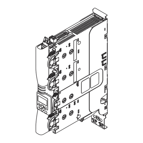
Technical data Dimensions Dimensions Standard device with installation backplane SSP94GGmSo000 Fig. 3−1 Dimensions [mm] Dimensions [mm] Weight Device size Type [kg] E94ASxE0024 E94ASxE0034 E94ASxE0044 E94ASxE0074 E94ASxE0134 E94ASxE0174 E94ASxE0244 EDK94ASH24 ZH/EN 4.1... -
Page 56: Example Circuit
Example circuit Example circuit F1...F3 E94AZPxxxxx X100 ƒ E94ASxExxxx . . . X106 X105 X107 U V W ‚ EYF... SSP94PSP01 E94ASxExxxx 9400 Single Drive servo axis module E94AZPxxxxx Installation backplane F1 ... F4 Fuses Mains filter/RFI filter (optional) "... -
Page 57: Mounting And Wiring The Installation Backplane
Mounting and wiring the installation backplane Mounting and wiring the installation backplane Note! The devices must be installed in housings (e.g. control cabinets) to meet applicable regulations. Mounting and wiring of the installation backplane is described in the Mounting Instructions for the installation backplane. -
Page 58: Mounting The Standard Device
Mounting the standard device Mounting the standard device How to proceed: 1. Insert the device into the installation backplane without twisting it until resistance is felt. 2. Press the device into the installation backplane until it audibly snaps into place. The locking clip moves downwards and back into the locking position. -
Page 59: Wiring Of The Standard Device
Wiring of the standard device Wiring of the standard device Danger! Dangerous electrical voltage All power terminals remain live for up to three minutes after mains disconnection. Possible consequences: Death or severe injuries when touching the power terminals. ƒ Protective measures: Switch off the power supply and wait for at least three minutes before ƒ... - Page 60 Wiring of the standard device System bus CAN on board Terminal X1 Labelling Description Pin 2 CAN−LOW Pin 3 CAN−GND Pin 7 CAN−HIGH 9400SSP000X1 (Housing) CAN−Shield Note! The X1 connection is not available in the "StateLine" design. 24 V supply Terminal X2 Labelling Description...
- Page 61 Wiring of the standard device Terminal X3 Labelling Description GND analog signals Analog input 1 + A1− Analog input 1 − A1− Analog input 1 − Terminating resistor for ±20mA " SSP94SL0X3 Shield connection: Fix the shield with EMC wire clamp. Digital outputs Terminal X4 Labelling...
- Page 62 Wiring of the standard device Digital inputs Terminal X5 Labelling Description GND digital in Controller enable Digital input 1 Digital input 2 Digital input 3 Digital input 4 Digital input 5 Digital input 6 Digital input 7 9400SSP000X5 Digital input 8 Terminal data Conductor cross−section Tightening torque...
- Page 63 Wiring of the standard device Resolver Terminal X7 Labelling Description +REF −REF +COS −COS +SIN −SIN +KTY 9400SSP000X7 −KTY Encoder Terminal X8 Labelling Description Cable EYF001... EYF002... − Hiperface EnDat 2.1 − − +RS485 Data (Z) Data + n. c. n.
-
Page 64: Wiring The Device Modules
Wiring the device modules Communication modules Wiring the device modules The equipment of the device with modules depends on the device variant or on the application. A short description of the different device modules follows. More detailed information is given in the corresponding documentation. Communication modules Use these modules in slot þ... - Page 65 Wiring the device modules Communication modules CANopen E94YCCA001B Fig. 8−2 E94AYCCA communication module (CANopen) Connections Pos. Description X220 Connection for CAN Design: Sub−D plug connector, 9−pin X220 Labelling Description Pin 2 CAN−LOW Pin 3 CAN−GND Pin 7 CAN−HIGH 9400SSP000X1 (Housing) CAN shield EDK94ASH24 ZH/EN 4.1...
- Page 66 Wiring the device modules Communication modules DIP switch Pos. Description Addressing of the bus node Baud CAN Address 9400CAN003 Fig. 8−3 Arrangement and labelling of the DIP switches For the DIP switches that are placed at the front the node address (labelling "1" ... "64") and ƒ...
- Page 67 Wiring the device modules Communication modules PROFIBUS E94YCPM001A Fig. 8−4 E94AYCPM communication module (PROFIBUS) Connections Pos. Description X200 External supply of the communication module Design: Plug connector with screw connection, 2−pole X201 Connection for PROFIBUS Design: Sub−D socket, 9−pole X200 Labelling Description 24 V external supply via a safely separated power supply unit (SELV/PELV)
- Page 68 For addressing purposes, every station must be given an unambiguous address. Valid address range: 1 126 The address can be set freely via the front−panel switch. Note! For S1 − S7 = OFF (Lenze setting): ƒ When switching on the module, the configuration set under code C00899 becomes active.
-
Page 69: Function Modules
− TTL input signal by encoder or encoder simulation The function of this cable has to be set in the basic device: Sense (sensor lead for voltage regulation, Lenze setting) Lamp control Enable TTL input signal by encoder or encoder simulation SUBD09010 EDK94ASH24 ZH/EN 4.1... - Page 70 Wiring the device modules Function modules Designation Explanation TTL output signal from encoder or encoder simulation +5 V ±6 % − TTL output signal from encoder or encoder simulation Enable Digital output signal TTL output signal from encoder or encoder simulation SUBD09010 Displays Pos.
-
Page 71: Memory Modules
Wiring the device modules Memory modules Memory modules Use these modules in slot o MXI1 oMXI2 þMMI oMSI. MM1xx MM1xx equipment 1 MB flash memory ƒ SSP94M0001 Fig. 8−5 E94AYM1x memory module Position Labelling Description − − External elements do not exist. MM2xx / MM3xx / MM4xx MM2xx equipment: 1 MB flash memory... - Page 72 Wiring the device modules Memory modules SSP94M1001 Fig. 8−6 Memory module with DIP switch (as of order designation E94AYM22) Baud CAN Address 9400CAN003 Fig. 8−7 Arrangement and labelling of the DIP switches For the DIP switches that are placed at the front the node address (labelling "1"...
-
Page 73: Safety Modules
Wiring the device modules Safety modules Safety modules Danger! When using safety modules, the notes and descriptions concerning the module type must be strictly observed. They contain important information for the "safe" execution of requested functions. Disregard of the information endangers both people and machines! Use these modules in slot o MXI1 oMXI2 oMMI þMSI. - Page 74 Wiring the device modules Safety modules SM100 Function Safe torque off ƒ (previously: safe standstill, protection against unexpected start−up) SSP94SM112 Fig. 8−9 E94AYAB safety module Connections Pos. Labelling Description Input first shutdown path GND potential for SI1/SI2 Input second shutdown path GND potential feedback 24 V voltage supply feedback Non−safe signalling output Safe pulse inhibit"...
- Page 75 Wiring the device modules Safety modules SM301 Functions Safe torque off (STO) ƒ (previously: safe standstill, protection against unexpected start−up) Safe stop 1 (SS1) ƒ Safe stop 2 (SS2) − in accordance with IEC 61800−5−2: see SOS ƒ Safe stop emergency (SSE) ƒ...
- Page 76 Wiring the device modules Safety modules SSP94SM321 Connections Pos. Description Safety address switch (in the left part of the housing) Module switch for parameter set adoption from the memory module X82.1 X82.2 Plug−in terminal strips for input and output signals X82.3 X82.4 Addressing...
- Page 77 Wiring the device modules Safety modules Terminal assignment Note! Provide for a sufficient strain relief, so that the terminals are not pulled from the plug connectors, in particular when you use rigid cables. X82.1 Labelling Description This part of the terminal strip is not assigned. GND SD−Out1 Safe monitor SD−Out1, channel B Safe monitor SD−Out1, channel A...
- Page 78 Wiring the device modules Safety modules X82.4 Labelling Description GND clock output GND SD−In4 Sensor input SD−In4, channel B Sensor input SD−In4, channel A GND clock output GND SD−In3 Sensor input SD−In3, channel B Sensor input SD−In3, channel A Restart acknowledgement input ("Acknowledge In Stop", 1−channel, bridged to X82.3/AIS) Cable cross−sections and tightening torques Type...
-
Page 79: Final Works
You need the following for commissioning: Keypad EZAEBK0001 ƒ Computer with Windows® operating system (XP or 2000) ƒ Lenze PC software »Engineer« ƒ Connection with the controller via an interface, e.g. ƒ – Diagnostic interface X6 with USB diagnostic adapter –... - Page 80 © 08/2014 Lenze Automation GmbH Service Lenze Service GmbH Postfach 10 13 52, D−31763 Hameln Breslauer Straße 3, D−32699 Extertal Hans−Lenze−Str. 1, D−31855 Aerzen Germany Germany +49 5154 82−0 008000 2446877 (24 h helpline) Ê Ê +49 5154 82−2800 +49 5154 82−1112 š...
Need help?
Do you have a question about the L-force 9400 and is the answer not in the manual?
Questions and answers