
Subscribe to Our Youtube Channel
Related Manuals for Lenze EVF9330-V Series


Summary of Contents for Lenze EVF9330-V Series
- Page 1 EDKVF93−03 Global Drive .MU| Information for the operator of the machine 9300 vector 45 ... 90 kW EVF9330−xV ... EVF9333−xV Frequency inverter...
- Page 2 9300vec160...
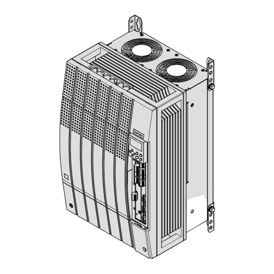
- Page 3 Key for overview Position Description Controller Fixing bracket for standard mounting EMC shield sheet with fixing screws for shielded control cables Cover with fixing screws Shield clamp and strain relief for the motor cable Strain relief for the PE motor cable and the feed cable for the motor temperature monitoring with PTC thermi- stor or thermal contact (NC contact) Connections and interfaces Position...
-
Page 4: Table Of Contents
............General safety and application notes for Lenze controllers . -
Page 5: About This Documentation
9300 vector series installed in your machine/system. You may make further use of the information contained in this documentation without asking Lenze for permission if you do not change the contents. Document history What is new / what has changed? -
Page 6: Validity Information
About this documentation Validity information Validity information ... 9300 vector frequency inverters as of nameplate data: ‚ ƒ Nameplate 93xx ˘ Vxxx 1x 8x Product series EVF = Frequency inverter Type no. / rated power 400V 480 V 9330 = 45 kW 55 kW 9331 = 55 kW 75 kW... -
Page 7: Conventions Used
About this documentation Conventions used Conventions used This documentation uses the following conventions to distinguish between different types of information: Type of information Identification Examples/notes Spelling of numbers Decimal separator language−dependen In each case, the signs typical for the target language are used as decimal separators. -
Page 8: Notes Used
About this documentation Notes used Notes used The following pictographs and signal words are used in this documentation to indicate dangers and important information: Safety instructions Structure of safety instructions: Danger! (characterises the type and severity of danger) Note (describes the danger and gives information about how to prevent dangerous situations) Pictograph and signal word Meaning... -
Page 9: Safety Instructions
Lenze Automation GmbH does not accept any liability for the suitability of the procedures and circuit proposals described. Depending on their degree of protection, some parts of the Lenze controllers ƒ (frequency inverters, servo inverters, DC speed controllers) and their accessory components can be live, moving and rotating during operation. - Page 10 Safety instructions General safety and application notes for Lenze controllers Application as directed Controllers are components which are designed for installation in electrical systems or machines. They are not to be used as domestic appliances, but only for industrial purposes according to EN 61000−3−2.
- Page 11 Reduce housing openings and cutouts to a minimum. Lenze controllers may cause a DC current in the PE conductor. If a residual current device (RCD) is used for protection against direct or indirect contact for a controller with three−phase supply, only a residual current device (RCD) of type B is permissible on the...
-
Page 12: Thermal Motor Monitoring
179 s in the event of a motor with a thermal motor time constant of 5 minutes (Lenze setting C0128), a motor current of 1.5 x I and a trigger threshold of 100 %. -
Page 13: Forced Ventilated Or Naturally Ventilated Motors
C0120 (OC6) or C0127 (OC8). Read release time in the diagram Diagram for detecting the release times for a motor with a thermal motor time constant of 5 minutes (Lenze setting C0128): = 1 × I L [%] = 3 ×... -
Page 14: Self−Ventilated Motors
C0129/x. Parameter setting The following codes can be set for I x t monitoring: Code Meaning Value range Lenze setting C0066 Display of the I x t load of the motor 0 ... 250 % − C0120 Threshold: Triggering of error "OC6"... - Page 15 Safety instructions Thermal motor monitoring Self−ventilated motors Calculate release time and I xt load Calculate the release time and the I x t load of the motor considering the values in C0129/1 and C0129/2(evaluation coefficient "y"). Formulae for release time Information Release time of the I x t monitoring...
-
Page 16: Residual Hazards
Safety instructions Residual hazards Residual hazards Protection of persons Before working on the controller, check that no voltage is applied to the power ƒ terminals: – Because the power terminals V, W, +U and −U remain live for at least 3 minutes after disconnecting from mains. - Page 17 Safety instructions Residual hazards Protection of the machine/system Drives can reach dangerous overspeeds (e. g. setting of high output frequencies in ƒ connection with motors and machines not suitable for this purpose): – The drive controllers do not provide protection against such operating conditions. For this purpose, use additional components.
-
Page 18: Safety Instructions For The Installation According To Ul
Safety instructions Safety instructions for the installation according to UL Safety instructions for the installation according to UL Original − English Warnings! Motor Overload Protection ƒ – For information on the protection level of the internal overload protection for a motor load, see the corresponding manuals or software helps. –... - Page 19 Safety instructions Safety instructions for the installation according to UL Original − French Warnings! Motor Overload Protection ƒ – For information on the protection level of the internal overload protection for a motor load, see the corresponding manuals or software helps. –...
-
Page 20: Parameter Setting
Parameter setting Parameter setting with the XT EMZ9371BC keypad General data and operating conditions Parameter setting Parameter setting with the XT EMZ9371BC keypad Description The keypad is available as an accessory. A full description of the keypad can be obtained from the Instructions included in the keypad delivery. -
Page 21: Installation And Commissioning
Parameter setting Parameter setting with the XT EMZ9371BC keypad Installation and commissioning 3.1.2 Installation and commissioning SHPRG Menu 0050 Code Para 50.00_Hz M C T R L - N O U T EMZ9371BC ‚ E82ZBBXC SHPRG Menu 0050 Code Para G L O B A L D R I V E I n i t... - Page 22 Parameter setting Parameter setting with the XT EMZ9371BC keypad Display elements and function keys Displays 0 Status displays of standard device Display Meaning Explanation Ready for operation Pulse inhibit is active Power outputs are inhibited The set current limit is exceeded in motor or generator mode Speed controller 1 in the limitation Drive is torque−controlled...
-
Page 23: Changing And Saving Parameters
Parameter setting Parameter setting with the XT EMZ9371BC keypad Changing and saving parameters Function keys Note! Shortcuts with T: Press and hold T, then press the second key in addition. Function Menu level Code level Parameter level Operating level Change to the Change to the operating Change to the code parameter level... - Page 24 Display of C0003 "PAR SAVE" 13. Set parameters for another parameter Restart the "loop" with step 1. or 3. The function of the S key can be programmed: C0469 = 1: Controller inhibit C0469 = 2: Quick stop (Lenze setting) EDKVF93−03 EN 3.0...
-
Page 25: Loading A Parameter Set
Parameter setting Parameter setting with the XT EMZ9371BC keypad Loading a parameter set 3.1.5 Loading a parameter set The keypad serves to load a saved parameter set into the main memory when the controller is inhibited. After the controller is enabled, it operates with the new parameters. Danger! When a new parameter set is loaded, the controller is reinitialised and acts ƒ... -
Page 26: Transferring Parameters To Other Standard Devices
Parameter setting Parameter setting with the XT EMZ9371BC keypad Transferring parameters to other standard devices 3.1.6 Transferring parameters to other standard devices Parameter settings can be easily copied from one standard device to another by using the keypad. For this purpose use the "Load/Store" menu Danger! During the parameter transfer from the keypad to the standard device the control terminals can adopt undefined states! - Page 27 Parameter setting Parameter setting with the XT EMZ9371BC keypad Transferring parameters to other standard devices Copying parameter sets fom keypad into the standard device Step Action sequence Connect the keypad to standard device 2 Inhibit controller Terminal X5/28 = LOW The "IMP"...
-
Page 28: Activating Password Protection
Parameter setting Parameter setting with the XT EMZ9371BC keypad Activating password protection 3.1.7 Activating password protection Note! If the password protection is activated (C0094 = 1 ... 9999), you only have ƒ free access to the user menu. To access the other menus, you must enter the password. By this, the ƒ... -
Page 29: Diagnostics
Parameter setting Parameter setting with the XT EMZ9371BC keypad Diagnostics 3.1.8 Diagnostics In the "Diagnostic" menu the two submenus "Actual info" and "History" contain all codes monitoring the drive ƒ fault/error diagnosis ƒ In the operating level, more status messages are displayed. If several status messages are active, the message with the highest priority is displayed. -
Page 30: Menu Structure
Parameter setting Parameter setting with the XT EMZ9371BC keypad Menu structure 3.1.9 Menu structure For simple, user−friendly operation, the codes are clearly arranged in function−related menus: Main menu Submenus Description Display Display User−Menu Codes defined in C0517 Code list All available codes All available codes listed in ascending order (C0001 ... - Page 31 Parameter setting Parameter setting with the XT EMZ9371BC keypad Menu structure Main menu Submenus Description Description Display Display LECOM/AIF Configuration of operation with communication modules LECOM A/B Serial interface AIF interface Process data Status word Display of status words System bus Configuration of system bus (CAN) Management CAN communication parameters CAN−IN1...
-
Page 32: Troubleshooting And Fault Elimination
(e.g. pressure, temperature, speed). Note! The calibration always affects all specified codes simultaneously. Codes for parameter setting Code Possible settings IMPORTANT Name Lenze Selection C0051 MCTRL−NACT −36000 {1 rpm} 36000 Actual speed value, function block MCTRL Read only C0052 MCTRL−Umot... -
Page 33: Diagnostics
— 4.1.2 Diagnostics Description Display codes for diagnostics Codes for parameter setting Code Possible settings IMPORTANT Name Lenze Selection C0093 DRIVE IDENT Controller identification Read only invalid Damaged power section none No power section 9321 9321VC Display of the controller used... -
Page 34: Troubleshooting
Troubleshooting and fault elimination Troubleshooting Status display via controller LEDs Troubleshooting Detecting breakdowns A breakdown can be detected quickly via the LEDs at the controller or via the status information at the keypad. Analysing errors Analyse the error using the history buffer. The list of fault messages gives you advice how to remove the fault. -
Page 35: Fault Analysis With The History Buffer
Troubleshooting and fault elimination Troubleshooting Fault analysis with the history buffer 4.2.2 Fault analysis with the history buffer Retracing faults Faults can be retraced via the history buffer. Fault messages are stored in the 8 memory locations in the order of their appearance. The memory locations can be retrieved via codes. -
Page 36: Drive Behaviour In The Event Of Faults
Troubleshooting and fault elimination Drive behaviour in the event of faults Fault analysis with the history buffer Drive behaviour in the event of faults The controller responds differently to the three possible fault types TRIP, message, or warning: TRIP TRIP (display in keypad XT: c A) Switches the power outputs U, V, W to a high−resistance state until TRIP reset is ƒ... -
Page 37: Fault Elimination
– The motor rotates faster than the speed setpoint by the value set in C0074 (influence of the speed controller, Lenze setting 10 % of n ). After the controller is enabled, it does not stop at zero speed setpoint or quick stop (QSP). -
Page 38: Controller In Clamp Operation
Troubleshooting and fault elimination Fault elimination Controller in clamp operation 4.4.2 Controller in clamp operation The clamp operation is a permissible operating mode. But since, however, pulse inhibit is set again and again, the controller cannot provide the optimum power. If the output power is optimal, the output current mainly is right below the clamp threshold. -
Page 39: Behaviour In Case Of Overvoltage In The Dc Bus (Ou Message)
480 V Operation without brake 770 V 755 V chopper 480 V Operation with brake 800 V 785 V chopper Lenze setting Codes for parameter setting Code Possible settings IMPORTANT Name Lenze Selection C0912 OV delay time à... -
Page 40: System Error Messages
OU is lower than the delay time set in C0912. The pulse inhibit is deactivated after the delay time in C0912 has elapsed. The delay time in [ms] is set under C0912. The Lenze setting can be changed by the ƒ... - Page 41 Troubleshooting and fault elimination System error messages General error messages Description Cause Remedy Fault message Display −−− −−− No fault − − 0011 Overcurrent in motor cable In the event of a short circuit Search for the cause of the >...
- Page 42 Troubleshooting and fault elimination System error messages General error messages Fault message Description Description Cause Cause Remedy Remedy Display x032 Motor phase failure A current−carrying motor phase Check motor. has failed. Check motor cable. Switch off monitoring (C0597 = 3). The current limit value is set too Set higher current limit value low.
- Page 43 Fault while loading a Set the required parameters set 2 parameter set. and save them with C0003 = 2. PLEASE NOTE: The Lenze setting is Interruption during the loaded automatically! transfer of the parameter set via keypad. The parameters saved do not...
- Page 44 Fault while loading a Set the required parameters set 3 parameter set. and save them with C0003 = 3. PLEASE NOTE: The Lenze setting is Interruption during the loaded automatically! transfer of the parameter set via keypad. The parameters saved do not...
-
Page 45: Resetting System Error Messages
Troubleshooting and fault elimination System error messages Resetting system error messages Fault message Description Description Cause Cause Remedy Remedy Display 0140 Error during motor data No motor connected. Check motor connection. identification. Stator resistance too high. Check entered motor data. Controller inhibited externally. - Page 46 © 11/2013 Lenze Automation GmbH Service Lenze Service GmbH Postfach 10 13 52, D−31763 Hameln Breslauer Straße 3, D−32699 Extertal Hans−Lenze−Str. 1, D−31855 Aerzen Germany Germany +49 5154 82−0 008000 2446877 (24 h helpline) Ê Ê +49 5154 82−2800 +49 5154 82−1112 š...
Need help?
Do you have a question about the EVF9330-V Series and is the answer not in the manual?
Questions and answers