Table of Contents
Advertisement
Quick Links
Advertisement
Table of Contents

Subscribe to Our Youtube Channel
Related Manuals for Sungrow SG40KTL


Summary of Contents for Sungrow SG40KTL
- Page 1 User Manual SG40KTL Grid-Connected Inverter ...
-
Page 2: About This Manual
1 Safety Instructions User Manual About This Manual This manual is for the inverter SG40KTL. The inverter is grid-connected, transformer-less, robust and of high conversion efficiency. The device will bring you profit from PV power system. The manual contains information about the inverter, providing you guidelines to connect the inverter into the PV power system and operate the inverter. - Page 3 User Manual 1 Safety Instructions Symbols on the Inverter Body This symbol indicates that you should wait at least 10 minutes after disconnecting the inverter from the utility grid and from the PV input before touching any inner live parts. Hot surface! In order to reduce the risk of burns, do not touch the hot surface when the device is running.
-
Page 4: Table Of Contents
1 Safety Instructions User Manual Contents About This Manual ..............2 1 Safety Instructions ............6 2 Product Introduction ............9 Intended Usage ................9 Product Description ..............10 2.2.1 Product Appearance ..............10 2.2.2 Dimensions of Inverter .............. 11 ... - Page 5 Maintenance ................45 9.2.1 Routine Maintenance ..............45 9.2.2 Maintenance Instruction ............45 Contact Sungrow Service ............47 10 Operation of LCD Display ..........48 10.1 Description of Button Function ..........48 ...
-
Page 6: 1 Safety Instructions
User Manual 1 Safety Instructions IMPORTANT SAFETY INSTRUCTIONS The SG40KTL has been designed and tested strictly according to the international safety regulations. As electrical and electronic equipment, safety instructions related to them must be complied with during installation, commissioning, operation and maintenance. Incorrect operation or work may result in damage to: ... - Page 7 User Manual 1 Safety Instructions PV arrays will produce electrical energy when exposed to sunlight and thus can create an electrical shock hazard. Wiring of the PV arrays should only be performed by qualified personnel. All cables must be firmly attached, undamaged, properly insulated and adequately dimensioned.
- Page 8 Use only accessories and spare parts approved by the inverter manufacturer. Never modify the inverter or the components of the inverter. Otherwise it may void any or all warranty rights from Sungrow. There is a risk of inverter damage due to electrostatic discharge!
-
Page 9: 2 Product Introduction
2 Product Introduction 2.1 Intended Usage SG40KTL (It will be referred to as inverter hereinafter unless otherwise specified) which is a 3-phase string inverter without transformer, is a crucial unit between the PV strings and utility grid in the PV power system. -
Page 10: Product Description
2 Product Introduction User Manual If the PV system exceeds the capacity of one inverter, it is possible to connect several inverters into the PV system, with each one connected to an appropriate section of PV inputs and on the AC side they connected in parallel to the grid. -
Page 11: Dimensions Of Inverter
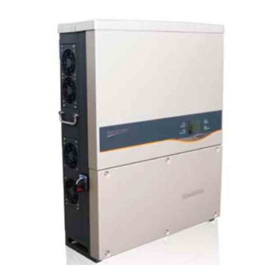
User Manual 2 Product Introduction 2.2.2 Dimensions of Inverter Fig. 2-3 Outline Dimensions of Inverter (unit: mm) 2.2.3 LCD Display Panel As a human-computer interaction interface, LCD display panel comprises LED indicators, buttons and LCD display screen on the front panel of the inverter. ... -
Page 12: Technical Description
2 Product Introduction User Manual Rotate the DC switch to the “ON” position, before restarting the inverter. 2.3 Technical Description 2.3.1 Principle Description PV strings input voltage is transmitted to DC BUS via Boost circuit. The inverter is equipped with MPPTs for two DC inputs to ensure that the maximum power can be utilized even in different PV modules installation conditions. -
Page 13: Derating
User Manual 2 Product Introduction Inverter provides various parameters configuration for optimal operation. Communication interface Standard RS485 interface for connecting other monitoring devices into the PV system is included. Protection functions − Short circuit protection − Insulation resistance to ground surveillance −... - Page 14 2 Product Introduction User Manual = Pn × (Vgrid / 277V) [Vmin…266V] Fig. 2-6 Grid Under-voltage Derating...
-
Page 15: 3 Installation Flow
3 Installation Flow Fig. 3-1 shows the installation flow of inverter. Please follow these procedures when installing the inverter. Start ? Fig. 3-1 Installation Flow Chart Tab. 3-1 Description of Installation Flow Reference Order Description Chapter Unpacking and inspection Section 4.1 Read this manual, especially the section on Chapter 1 “safety instruction”... -
Page 16: 4 Unpacking And Storage
It provides information on type of inverter, along with the most important specifications, marks of certification institutions, website and serial number which is available and identified by Sungrow. Fig. 4-2 Nameplate of Inverters *Image shown here is for reference only. Actual product you receive may differ. -
Page 17: Delivery Contents
User Manual 4 Unpacking and Storage Item Description SUNGROW logo and product type Technical data of inverter Marks of certification institutions of inverter Company name, website and origin Tab. 4-1 Description of Icons on the Nameplate Icon Description Don’t dispose of the inverter with the household waste. -
Page 18: Storage Of Inverter
During the storage time, periodically check any visible damage by rats and other rodents. Replace the packaging if necessary. The packaging should be kept upright. After long term storage, local installer or service dept. of Sungrow should perform a comprehensive test before connecting the inverter into PV power system. -
Page 19: 5 Installing Inverter Onto Wall
5 Installing Inverter onto Wall 5.1 Selecting Installation Location Selecting an optimal installation location for the inverter is decisive for its operating safety as well as its expected efficiency and service life. Take the load capacity of the wall into account. The wall (such as concrete wall and metal structure) should be strong enough to hold the weight of the inverter over a long period of time. - Page 20 5 Installing Inverter onto Wall User Manual The inverter unit with IP65 can be installed indoors or outdoors also. The ambient temperature should range from -25°C to 60°C . The relative humidity at the installation can reach 100%. ...
-
Page 21: Moving Inverter To Installation Site
User Manual 5 Installing Inverter onto Wall 5.2 Moving Inverter to Installation Site If the inverter is to be installed, remove the unit from the packaging and move it to the chosen installation site. During the moving process, the following instructions should be obeyed. -
Page 22: Installing On Metal Frame
5 Installing Inverter onto Wall User Manual In order to avoid electrical shock or other injury, inspect existing electronic or plumbing installations before drilling holes. Attach the backplate to the wall firmly with the supplied expansion bolt Step 5 set. The torque for fastening the nut is 35 Nm. Assemble the cap onto the inverter for better weatherproof function. - Page 23 User Manual 5 Installing Inverter onto Wall Fasten the backplate against the metal frame with bolts and nuts. The Step 5 dimensions of fasteners used in the following diagram are recommended. The torque for fastening the nut is 35 Nm. Item Description Remark...
-
Page 24: 6 Electrical Connection
6 Electrical Connection Once the inverter is firmly attached to the appropriate location, it can be connected to the PV power system. Installation shall comply with local regulations and technical rules. Installation shall comply with the relevant instructions of AS 4777.1. All electrical connection should follow the National Wiring Rules of Standard AS/NZS 3000. - Page 25 Voltage grid. Requirements: Max. grid-connected power is 1.6MVA. Please contact Sungrow for technical evaluation if the grid-connected power exceeds 1.6MVA. Scenario 2: Several inverters are operated in parallel connection to low-voltage side of MV transformer. The high-voltage side of MV transformer is connected to the Middle Voltage Grid.
-
Page 26: Grid Connection
6 Electrical Connection User Manual See technical information “Technical notes for multiple-paralleled grid-connected inverters” in the download area www.sungrowpower.com for more detailed information 6.2.2 Grid Connection An AC terminal block inside the connection cabinet is used for the five-wire grid connection (L1, L2, L3, N, PE) of the inverter. -
Page 27: Connecting Inverter To Pv Arrays
User Manual 6 Electrical Connection Description Remark Accepted cable external diameter ranges Protective layer from 22mm to 27mm. Length of insulation to be 16 mm stripped off Insulation layer Cross section Max. value: 16mm cables Each individual terminal of the terminal board accepts a cable with cross-section of up to 16 mm The table shows the maximum length of the cable conductor based on the cross-section. -
Page 28: Pv Inputs Configuration
6 Electrical Connection User Manual and the impedances between the negative terminal of the PV string and Earth are larger than 1Mohm. 6.3.1 PV Inputs Configuration The inverter has two PV input areas DC1 input and DC2 input, each with its MPP tracker. -
Page 29: Pv Connection Procedures
6.3.2 PV Connection Procedures DC cables from PV strings should be equipped with DC connectors. Sungrow provides corresponding plug connectors in the scope of delivery for quick connection of PV inputs. Pairs of MC4 DC connectors are supplied in the... - Page 30 6 Electrical Connection User Manual To maintain IP65 weatherproof function of inverter, only the supplied DC connectors or the connectors of the same protection class can be used. DC Cable Requirements Tab. 6-1 DC Cable Requirements Max. Max. Input Cross-section Outer Cable Withstand Current for Each...
- Page 31 User Manual 6 Electrical Connection Disconnect the DC switch. Step 7 Configure PV configuration mode via jumper cables according to actual Step 8 PV conditions. Please refer to”6.3.1 PV Inputs Configuration”. If inverter selects parallel PV configuration mode, you should connect DC1+ to DC2+ and DC1- to DC2- on the DC connection circuit board by inserting jumper cables of cross-section not less than 6mm (10 AWG) as the following diagram...
-
Page 32: Grounding The Inverter
6 Electrical Connection User Manual Connect other strings following above-mentioned Step 11 procedures. Seal the unused DC terminals with the waterproof plugs. Step 12 6.4 Grounding the Inverter Because of the transformer-less design of the inverter, neither the DC positive pole nor the DC negative pole of the PV string is permitted to be grounded. -
Page 33: Communication Connection
User Manual 6 Electrical Connection Second PE Terminals There is a second PE terminal on one side of the inverter. Users may choose to connect PE connection. Fig. 6-3 Second PE Terminals Second PE Connection Item Description Remark Screw M4×12mm Lock washer Washer Cable socket... -
Page 34: Communication System
6 Electrical Connection User Manual RS485 cable’s requirements to ensure quality of communication: RS485 shielded twisted pair cables Shielded network cable The diameter of the cable outside diameter should be in the range of 5.1~ 6.5mm. A converter such as RS485-232 converter or SolarInfo Logger, which converts 485 to 232 signal, is needed between inverter and 6.5.2 Communication System For Single Inverter... -
Page 35: Rs485 Communication Connection
If there is more than one inverter to communicate with a PC or a data logger, it is crucial to configure the communication parameters of each inverter. See “10.12 Communication Parameters Setting”. SolarInfo logger and RS485-232 converter are optional parts and can be ordered from Sungrow. - Page 36 If there is more than one inverter to communicate with a PC or a data logger, it is crucial to configure the communication parameters of each inverter. See “10.12 Communication Parameters Setting”. SolarInfo logger and RS485-232 converter are optional parts and can be ordered from Sungrow.
-
Page 37: 7 Commissioning
DC power. PV arrays initialize and supply DC power to inverter. The LCD display is activated to check the validity first. If there is a defect on the display, contact Sungrow. Press to choose country code. Confirm Step 3 ... - Page 38 7 Commissioning User Manual If the country code set as TH, a Grid codes Step 5 page special for Thailand will appear. Press to select grid code. Confirm the selection by Pressing ENTER. If the country code set as RO or AT, a LVRT Param page as shown in the right will appear.
- Page 39 User Manual 7 Commissioning Configure time according to the local Step 10 time. Time setting is very important, which directly affects data logging. Press move cursor and Press to scroll up time value. Confirm the settings by Pressing ENTER Step 11 After configuring all parameters, there...
-
Page 40: 8 Disconnecting, Dismantling And Disposing The Inverter40
8 Disconnecting, Dismantling and Disposing the Inverter 8.1 Disconnecting the Inverter For maintenance work or any service work, inverter must be switched off. In normal operation, switching off is not necessary. In order to disconnect the inverter from the AC and DC power sources, you should proceed as follows. -
Page 41: 9 Troubleshooting And Maintenance
2. Perform troubleshooting in according to fault type in LCD is lit screen. See “9.1.2 Troubleshooting of Faults in LCD Screen”. 3. If it cannot be solved, please contact Sungrow. 1. Warning fault occurs of the inverter. “RUN” indicator 2. Perform troubleshooting in according to fault type in LCD is blinking screen. - Page 42 Islanding 3. Check whether grid is not in service. 4. If all conditions are OK and this fault still occurs in the LCD screen, contact Sungrow Service Dept.. The DC component of 1. Wait a moment for inverter recovery.
- Page 43 Fault with DC SPD Contact Sungrow Service Dept.. Disconnect the inverter and replace the Fuse has blown out fuses. Contact Sungrow Service Dept.. A fault has occurred in the internal Communication fault of communication of the inverter. However, the inverter continues feeding into the grid.
- Page 44 User Manual Fault Description Troubleshooting Code and the warning fault still exists, please contact Sungrow Service Dept.. PVS(X) reverse polarity warning of PV1 1. Check the polarity of the PV1 inputs, if ( X represents the the polarity is reverse, please reconnect PV...
-
Page 45: Maintenance
Devices Replace the fuse. Every 6 months check Contact Sungrow to order new DC SPDs. 9.2.2 Maintenance Instruction Fans’ Maintenance There are four fans at the side of the inverter for active cooling during running operation. If the fans are dirty or out of work, the inverter may not be well cooled down and its efficiency may accordingly decrease. - Page 46 Check the affected string by installer of the PV generator and replace the Step 6 defective string fuse with same specification (order from Sungrow). Remove the blown string fuse. Step 7 Insert the new fuse into the fuse holder.
-
Page 47: Contact Sungrow Service
User Manual 9 Troubleshooting and Maintenance 9.3 Contact Sungrow Service Should you have any problems in operating on the inverter, please contact us: Service hotline: +86 551 65327817 Email: service@sungrow.cn We need the following information to provide you the best assistance: ... -
Page 48: 10 Operation Of Lcd Display
10 Operation of LCD Display 10.1 Description of Button Function Inverter offers two buttons for user to look up the running information and configure parameters. The two buttons have multiple functions. Please refer to 0before any operation onto inverter. Tab. 10-1 Button Function Button Operation Description... -
Page 49: Inverter Menu Structure
User Manual 10 Operation of LCD Display 10.2 Inverter Menu Structure Fig. 10-1 Menu Tree-English 10.3 Main Screen If the inverter succeeds in commissioning, LCD display will enter into the main screen, as shown in Fig. 10-2. Fig. 10-2 Main Screen Description... -
Page 50: Adjust Contrast
10 Operation of LCD Display User Manual Fig. 10-3 Description Power curve. x-axis: time in hours; y-axis: output power yield P in %. Icons (refer to the Tab. 10-3) and the Inverter active power limits (P-W limits). Current output power. Energy generation during this day until now. -
Page 51: Detailed Running Information
User Manual 10 Operation of LCD Display The contrast value ranges from 0 to 100%. The recommended value is 50% or 60%. 10.5 Detailed Running Information On the main screen, there is some basic information about the inverter. For more detailed running information, please operate as follows. Main Screen(Press ENTER)→Menu→Run-info(Press ENTER)... -
Page 52: Fault Records
10 Operation of LCD Display User Manual Inverter shows historical running information pages. Scroll pages pressing . Change to next record pressing . 10.6.2 Fault Records → → ) ) ENTER ENTER Main Screen(Press Menu(Press His-record(Press )→Flt-record(Press ) Press ENTER Inverter shows fault record pages. -
Page 53: System Parameters Setting
User Manual 10 Operation of LCD Display Press to confirm the password ENTER and .enter the “Set-param” sub menu. 10.9 System Parameters Setting Main Screen(Press ENTER)→Menu screen(Press ×3) →Set-param(Press ENTER)→Enter password(Press ENTER)→Sys-param(Press ENTER). On the “Sys-param” screen, you can set the time, adjust the energy, load default and check the firmware version. -
Page 54: Firmware Version
10 Operation of LCD Display User Manual ×3)→Set-param(Press Main Screen(Press ENTER)→Menu screen(Press ENTER)→Enter password(Press ENTER)→Sys-param(Press ENTER, Press ×3)→Load default(Press ENTER) A password confirmation screen will occur. Press move cursor right and Press to input the password 111111. Press ENTER to confirm “load default”. -
Page 55: Reactive Power Regulation
User Manual 10 Operation of LCD Display Fig. 10-4 “IT” Over-frequency Derating Curve 10.10.2 Reactive Power Regulation The inverter provides reactive power regulation function. Use the “ ” Q-Var switch parameter to activate this function and select proper regulation mode. Mode Explanation The reactive power can be regulated by the parameter PF (Power... - Page 56 10 Operation of LCD Display User Manual Fig. 10-5 Reactive Power Regulation Curve in Q(P) Mode Italy “Q(P)” Mode(when the country selection is “IT”) The power factor changes with the output power of the inverter. Select Q(P) mode and Press ...
- Page 57 User Manual 10 Operation of LCD Display “Q(U)” Mode(when the country selection is not “IT”) The reactive power ratio changes with the grid voltage. If the country selection is not “IT” (Italy), after selecting Q(U) mode, Press to enter the Run-param-Q(U) sub-menu.
-
Page 58: Save P/Q-Set
ENTER) → Enter password(Press ENTER, Press × 2) → Pro-param(Press ENTER) A password confirmation screen will occur. Press to move cursor right and Press to input the password. Please ask Sungrow or your dealer for this password. -
Page 59: Pro-Param Setting
User Manual 10 Operation of LCD Display To make protective parameters setting convenient, Inverter provides country code selection. The protective parameters have been configured before delivery according to different countries utility grid requirements. Choose the correct country code by Press and Press ENTER... -
Page 60: Single-Stage Protection Parameter Setting
10 Operation of LCD Display User Manual If the country code set as other countries. You may choose Single-stage or Multi-stage. Press to select protective parameter type. Press ENTER to confirm the selection. 10.11.3 Single-stage Protection Parameter Setting selected protective parameter type... -
Page 61: Multi-Stage Protective Parameter(When The Country Selection Is "It")
User Manual 10 Operation of LCD Display 10.11.5 Multi-stage Protective Parameter(when the country selection is “IT”) selected protective parameter type is “Multi-stage” “[ Ⅱ ]”, following sub-menus will come up. Press to select parameter, Press to move cursor right ... -
Page 62: Communication Parameters Setting
10 Operation of LCD Display User Manual 10.12 Communication Parameters Setting ×3)→Set-param(Press Main Screen(Press ENTER )→Menu screen(Press ENTER) → Enter password(Press ENTER, Press × 3) → Com-param(Press ENTER) Press to move cursor right and Press to set the appropriate value. -
Page 63: Fre Derating
User Manual 10 Operation of LCD Display When the PV inputs are changed, the corresponding “fault” state will be shown on the main screen. You can perform the PVS Detect Reset function to re-detect the PV input strings number. PVS Detect is only valid in the machine that is equipped with this feature. -
Page 64: Grid-Pro
10 Operation of LCD Display User Manual 10.13.4 Grid-pro ) → Menu screen(Press × 4) → Advanced Main Screen(Press ENTER settings(Press ENTER) → Enter password(Press ENTER) → Advanced settings(Press ENTER, Press ×3)→Grid-pro Grid-pro can set the over-voltage protection point in 10min and the Grid voltage unbalance protection point. -
Page 65: 11 Appendix
11 Appendix 11.1 Technical Data Parameters SG40KTL Input Side Data Max. PV input power 40500W Max. PV input voltage 1000V Startup voltage 300V Nominal input voltage 710V MPP voltage range 280…950V MPP voltage range for nominal 560...800V power No. of MPPT(s) Max. -
Page 66: Terminals And Cables
Damages caused by irresistible natural environment The use of supplied software produced by Sungrow Power Supply Co., Ltd. is subject to the following conditions: Sungrow Power Supply Co., Ltd. rejects any liability for direct or indirect damages arising from the use of the SolarInfo software. -
Page 67: About Us
The power rating of Sungrow products covers from hundred watt to mega-watt systems. The vision of Sungrow is to help our customers acquire stable and clean power with minimum cost, maximum reliability and enhanced safety. Contact Information Should you have any question about this product, please contact us.
Need help?
Do you have a question about the SG40KTL and is the answer not in the manual?
Questions and answers