Table of Contents

Subscribe to Our Youtube Channel
Related Manuals for Sungrow SG3150UD-MV-US


Summary of Contents for Sungrow SG3150UD-MV-US
- Page 1 System Manual MV Grid-Connected Inverter SG3150UD-MV-US/SG4400UD-MV-US SG3150UD-MV-US/ MV Grid-Connected SG4400UD-MV-US InverterSystem ManualSG3150_ 4400UD-MV-US-SEN-Ver18- 202312M-D-000313 SG3150_4400UD-MV-US-SEN-Ver18-202312...
-
Page 3: All Rights Reserved
Software Licenses • It is prohibited to use data contained in firmware or software developed by SUNGROW, in part or in full, for commercial purposes by any means. • It is prohibited to perform reverse engineering, cracking, or any other operations that... -
Page 5: Table Of Contents
Contents All Rights Reserved .....................I 1 About This Manual ...................1 1.1 Validity......................1 1.2 Target Group ....................1 1.3 How to Use This Manual .................1 1.4 Symbol Explanations ..................2 2 Safety Instructions ....................3 2.1 Unpacking and Inspection ................4 2.2 Hoisting and Transportation................5 2.3 Electrical Connection ..................5 2.4 Operation.......................7 2.5 Operation and Maintenance ................7... - Page 6 5.2 Inspection Before Installation.................20 5.2.1 Scope of Delivery ................20 5.2.2 Product Inspection ................21 5.3 Installation Environment Requirements ............21 5.3.1 Installation Site ...................21 5.3.2 Foundation ..................21 5.3.3 Installation Spacing ................22 5.4 Hoisting and Fixing ..................22 5.4.1 Preparation Before Hoisting ..............22 5.4.2 During Hoisting ...................23 5.4.3 Fixing ....................24 5.5 Installing Brackets ..................25 6 Electrical Connection...
- Page 7 6.9.1 5KVA Power Distribution Cabinet ............42 6.9.2 40KVA Power Distribution Cabinet............43 6.9.3 Recommended Cables Installation ............43 6.10 Check After Wiring..................44 6.10.1 Inspection ..................44 6.10.2 Locking Cabinet Door ................44 6.10.3 Fixing Cable..................45 7 Powering up and Powering down ..............46 7.1 Safety Instructions ..................46 7.2 Powering Up Operations ................46 7.2.1 Removing Film on Product..............46 7.2.2 Removing Pressure Relief Screw ............48...
- Page 8 8.4.5 Setting Initial Parameters..............56 8.4.6 Setting Operation Parameters ..............57 8.4.7 Setting System Parameters ..............57 8.4.8 Setting Protection Parameters..............57 8.5 Modifying Password..................58 8.6 Logout ......................58 9 Operation Mode ....................59 9.1 Mode Change ....................59 9.2 Operation Mode Description ................59 10 Troubleshooting ....................62 10.1 Inverter Troubleshooting ................62 10.1.1 Viewing Fault/Alarm Information ............62 10.1.2 Check Method...................62...
- Page 9 11.5 Replacing Fans...................89 12 Cyber Security Protocol ................91 12.1 Password Change Requirements..............91 12.2 Port Protection and Isolation................91 12.3 Network Cables and Tamper Evident Seals Inspection ........91 13 Cybersecurity Best Practice ...............93 14 Appendix .......................94 14.1 Technical Parameters .................94 14.2 Tightening Torques ..................96 14.3 Quality Assurance ..................96 14.4 Contact Information ..................97...
-
Page 11: About This Manual
The products and product manuals are always in the process of improvement and upgrade. If the manual received is slightly inconsistent with the product, it may be a result of a product version upgrade, and the actual product shall prevail. For any questions, please contact Sungrow Customer Service. -
Page 12: Symbol Explanations
1 About This Manual System Manual Symbol Explanations To ensure the safety of the users and their properties when they use the product and to make sure that the product is used optimally and efficiently, this manual provides users with the relevant safety information which is marked by the following symbols. -
Page 13: Safety Instructions
Level 6 or stronger winds. SUNGROW shall not be held liable for any damage to the device due to force majeure, such as... -
Page 14: Unpacking And Inspection
Perform operations considering ac- tual onsite conditions. • SUNGROW shall not be held liable for any damage caused by violation of gen- eral safety operation requirements, general safety standards, or any safety in- struction in this manual. -
Page 15: Hoisting And Transportation
System Manual 2 Safety Instructions Hoisting and Transportation Risk of personal injury or device damage due to incorrect operation! • Follow the procedure of work of heights when walking on the top of the product. • All hoisting and transportation must comply with the relevant codes and regula- tions of the nation/region where the project is located. - Page 16 2 Safety Instructions System Manual PV modules will generate lethal high voltage when exposed to sunlight. • Operators must wear proper personal protective equipment during electrical connections. • Before performing an electrical connection, be sure to disconnect the PVS and use measuring equipment to ensure that cables are voltage-free.
-
Page 17: Operation
System Manual 2 Safety Instructions Operation When the product is working, • It is strictly forbidden to touch the live parts of the product. Otherwise, an elec- tric shock may occur. • It is strictly prohibited to disassemble any parts of the product. Otherwise, an electric shock may occur. - Page 18 To avoid the risk of electric shock, do not perform any other maintenance opera- tions beyond those described in this manual. If necessary, contact SUNGROW for maintenance. Otherwise, the losses caused are not covered by the warranty.
-
Page 19: Disposal
System Manual 2 Safety Instructions Disposal Please scrap the inverter in accordance with relevant local regulations and stand- ards to avoid property losses or casualties. -
Page 20: Product Description
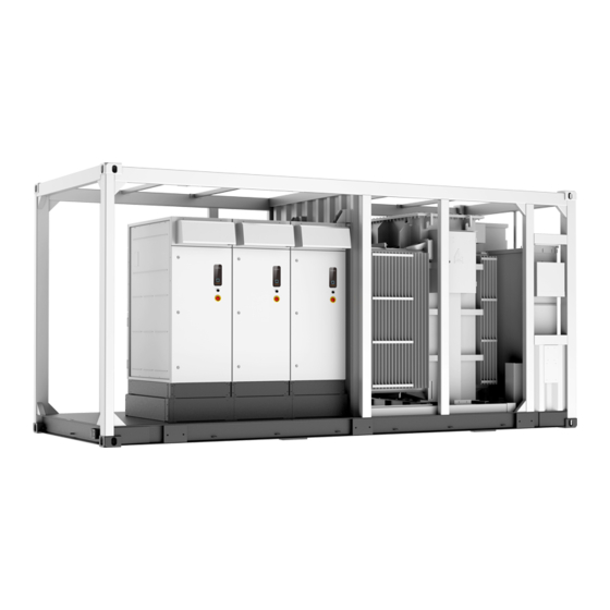
Product Description Product Introduction In large and medium-sized utility power plant systems, the MV grid-connected inverter, which contains multiple PV inverter units, transformers, and other equipment, provides a sound solution to convert the DC power generated by PV arrays into AC power, and feed it into the grid. -
Page 21: Main Internal Equipment
System Manual 3 Product Description * The figure is for reference only. And the actual product received shall prevail. Name Description Convert the DC power generated by PV modules Inverter units into AC power. Convert the low-voltage AC power output by inver- Transformer ter units into medium-voltage AC power. -
Page 22: Internal Structure Of Inverter Unit
3 Product Description System Manual Name Top air inlet Indicator panel DC knob switch. Disconnect the DC load switch. Emergency stop button. In case of emergency, press this button to open the AC circuit breaker and DC load switch. Base LED Indicator table 3-1 Indicator Status Description Description... -
Page 23: Main Parts Of Transformer
System Manual 3 Product Description * The figure is for reference only. And the actual product received shall prevail. Description Name Disconnect it before maintenance and repair. Maintenance switch QS2 Control the on/off of the DC side circuits of the DC load switch QS1 inverter. - Page 24 3 Product Description System Manual Graphics Description Name Oil level gauge Indicate the level of stored oil in the transformer. De-energized tap- Adjust the output voltage of the transformer. changer Drain valve and Drain the oil from the transformer into a container sampling valve through a clean hose.
-
Page 25: Load Switch
System Manual 3 Product Description Graphics Description Name Pressure gauge Read the pressure value inside the oil tank. The alarm threshold is 95 ℃. An alarm signal is sent if the oil temperature reaches 95 ℃. Oil temperature gauge The tripping threshold is 100 ℃. A tripping signal is sent if the oil temperature reaches 100 ℃. - Page 26 3 Product Description System Manual Explanation Marks It is recommended to wear noise-cancellation earplugs since the product may generate noise during operation. It is strictly forbidden to touch the fan blades when the fan is rotating. Read this manual carefully before any operation on the product. Do not dispose of this product as household waste.
-
Page 27: Transport And Storage
Transport and Storage Precautions Failure to transport and store the product in accordance with the requirements in this manual may invalidate the warranty. Transportation Requirements • Choose appropriate means of transportation according to the size and weight of the product. •... -
Page 28: Protection During Storage
• For a product shut down/stored for over six months, inspect its electrical components (IGBT module, switch, etc.), and take dehumidifcation and dedusting mesaures for the whole product. For detailed operation, please contact SUNGROW. -
Page 29: Mechanical Mounting
If there are prob- lems with the above inspection items, do not install the product and contact SUNGROW in time. -
Page 30: Inspection Before Installation
5 Mechanical Mounting System Manual Improper hoisting may cause personal injury! • It is strictly prohibited to stand within 5m - 10m outside the operating area (i.e., under the boom and the hoisted machine) to avoid casualties. • Only professional personnel can operate the product, and be sure to wear per- sonal protective equipment when operating. -
Page 31: Product Inspection
• Visually check the product for any damage. If any problems are found or there is any question, please contact the forwarding company or SUNGROW. Only install the product when it is complete and intact. Before installation, ensure that: •... -
Page 32: Installation Spacing
5 Mechanical Mounting System Manual • Pre-bury the threading pipe at the bottom of the foundation according to the location of the cable inlet holes at the bottom of the product. • A drainage system is necessary to prevent the bottom or internal equipment of the prod- uct from being soaked in water during the rainy season or during heavy rainfall. -
Page 33: During Hoisting
System Manual 5 Mechanical Mounting 5.4.2 During Hoisting • Ensure safe and reliable connections of all slings. • Ensure that the product is steady and not tilting during the whole hoisting process. • The product should be hoisted vertically. Never drag the product on the ground or the top of the lower product, and never pull and push it on any surface. -
Page 34: Fixing
5 Mechanical Mounting System Manual figure 5-3 Hoisting by Two Cranes Be sure to hoist the product smoothly and evenly to avoid collision and vibration. Do not turn the product upside down, nor hoist it for a long time. Otherwise, per- sonal injury or product damage may occur! 5.4.3 Fixing Hoist the product to the intended location and fix it. -
Page 35: Installing Brackets
System Manual 5 Mechanical Mounting Installing Brackets The product is equipped with three brackets, as highlighted in the figure below, which can be used for the installation of SCADA, weather station, and Ethernet switch, etc. -
Page 36: Electrical Connection
Electrical Connection Precautions • Before electrical connections, please make sure that the inverter is not dam- aged, otherwise, it may cause danger! • Before electrical connections, please make sure that the product switch and all switches connected to the product are set to "OFF", and use measuring equip- ment to ensure that there is no voltage at the connection. -
Page 37: Wiring Overview
System Manual 6 Electrical Connection Damage to the device caused by incorrect wiring is not covered by the warranty. • Electrical connection must be performed by professional personnel who wear personal protective equipment. • The cables used in the PV generation system must be firmly connected, in good condition, and well insulated to appropriate sizes. -
Page 38: Preparation Before Wiring
6 Electrical Connection System Manual 1- Inverter 2– Transformer 3– Power Distribution Cabinet table 6-1 Interface Description Description Recommended Cable Specifications DC input port 750MCM (400 mm ) at most AC output port 2/0 AWG — 1250 MCM (70 mm —... - Page 39 System Manual 6 Electrical Connection Heat gun Torque screwdriver Wire stripper Hydraulic clamp Torque wrench Multimeter Electric drill Screwdriver Protective gloves Goggles Insulated shoes Protective clothing Hard hat...
-
Page 40: Open Product Door
6 Electrical Connection System Manual 6.3.2 Open Product Door Step 1 Remove the M8 bolts at the upper and lower ends of the removable beam around the product. Step 2 Open the cabinet door. Step 3 Fix the doors of the inverter unit cabinet and power distribution cabinet. Step 4 Remove the protective cover of the wiring area. -
Page 41: Position Of Cable Inlet
System Manual 6 Electrical Connection • Select cables with a proper diameter according to the maximum load, and the cables should be long enough. • All DC input cables must be of the same specifications and materials. • AC output cables of three phases must be of the same specifications and materials. •... -
Page 42: Ground Connection
AC cables, DC cables, and communication cables. • Both grounding terminals on the side of the product must be connected to the protective grounding points reliably. SUNGROW shall not be held liable for any damage caused by the violation. -
Page 43: Overview
System Manual 6 Electrical Connection Note the following during ground connection: • Observe specific codes and regulations of the country/region where the project is located to perform ground connections. • All grounding connections inside the PV system must be secure and reliable. •... -
Page 44: Dc Input Connection
6 Electrical Connection System Manual 1: Heat shrink tubing 2: OT/DT terminal DC Input Connection The PV string will generate lethal high voltage when exposed to sunlight. Respect all safety instructions listed in relevant documents about PV strings. • Make sure the PV array is well insulated to the ground before connecting it to the inverter. -
Page 45: Installing Insulation Board Before Connection
System Manual 6 Electrical Connection All shown in the figures are 7-way DC input. When DC Input is 6-way, remove the rightmost DC fuse and DC wiring copper bar; When the DC input is 5-way, remove one DC fuse and DC wiring copper bar from each end on the left and right. 6.5.2 Installing Insulation Board before Connection Installing insulation board before cable connections. - Page 46 6 Electrical Connection System Manual Step 3 Install the OT/DT terminal to the wire and crimp them with a crimping tool. Install a heat shrink tubing to the terminal and heat it with a heat gun. Step 4 Secure the OT/DT terminal to the copper bar by M12 x 45 bolts with a tightening torque of 60- 70 N.m.
-
Page 47: Ac Side Connection
System Manual 6 Electrical Connection Step 5 Pull the cable back slightly after wiring to ensure that the cable is long enough. • Ensure that the selected terminal can directly contact the copper bar. If there are any problems, contact the terminal manufacturer. •... - Page 48 6 Electrical Connection System Manual Step 2 Lead external cables inside through the bottom cable entries. Each of the three-phase (phase H1, phase H2, and phase H3) cables is led inside through the same cable entry.
- Page 49 System Manual 6 Electrical Connection Step 3 Prepare the terminals and install them tightly, where reference can be made to the installation manual of the cable connector. Both cooper-core cable and aluminium-core cable are applicable. In case of copper-core cables, use copper wiring terminals. In case of aluminium cables, use copper-to-aluminium adapter terminals.
-
Page 50: Communication Connection
6 Electrical Connection System Manual After completing wiring, fix the cable on the beam (not included in the scope of supply) to avoid excessive stress on the cable. Seal the bottom cable entries with fireproof mud (foaming materials), remove debris in the HV cabinet, close and lock the cabinet door. -
Page 51: Ethernet Communication
System Manual 6 Electrical Connection Step 4 Loosen the screwdriver, the metal plate returns and compresses the cable. * The figure is for reference only. The product received may differ. - - End Ethernet Communication Overview The Ethernet communication port in the power distribution cabinet is shown in figure A below. -
Page 52: 5Kva Power Distribution Cabinet
6 Electrical Connection System Manual Unless the MV transformer disconnect switch is open, 645V AC may be present in the Power Distribution Cabinet. 6.9.1 5KVA Power Distribution Cabinet Internal Components Cable Size (AWG) Name QS8* Control switch for self-constructed grid Control switch for auxiliary transformer Control switch for 120Vac power supply Reserved for 120Vac power supply... -
Page 53: 40Kva Power Distribution Cabinet
System Manual 6 Electrical Connection 6.9.2 40KVA Power Distribution Cabinet Internal Components Please refer to the actual product for the specific wiring diagram. 6.9.3 Recommended Cables Installation The Ethernet and terminal blocks cables in the power distribution cabinet are recommended to be wired as shown in the following figure. -
Page 54: Check After Wiring
6 Electrical Connection System Manual * The figure is for reference only. And the actual product received shall prevail. 6.10 Check After Wiring 6.10.1 Inspection Check the wiring thoroughly and carefully when all electrical connections have been completed. • Seal the gap between cables and the wiring holes with fireproof and waterproof materials. •... -
Page 55: Fixing Cable
System Manual 6 Electrical Connection Step 2 Lock the cabinet door and pull out the key. Electric shock hazard! Be sure to lock the cabinet door. Otherwise, non-professionals may be exposed to the running machine, and it may cause casualties. - - End 6.10.3 Fixing Cable There is no cable fixing point inside the product, and the cable needs to be fixed within 500... -
Page 56: Powering Up And Powering Down
Powering up and Powering down Safety Instructions When the product is working: • It is strictly forbidden to touch the live parts of the product. Otherwise, an elec- tric shock may occur. • It is strictly prohibited to disassemble any parts of the product. Otherwise, an electric shock may occur. - Page 57 System Manual 7 Powering up and Powering down figure 7-1 Remove Film at Air Inlet of Inverter figure 7-2 Remove Film at Air Outlet of Inverter Films Distribution Area of Power Distribution Cabinet figure 7-3 Remove Film at Air Inlet and Outlet of Power Distribution Cabinet * The figure is for reference only.
-
Page 58: Removing Pressure Relief Screw
7 Powering up and Powering down System Manual 7.2.2 Removing Pressure Relief Screw Be sure to remove the pressure relief screws (marked as A in the figure below) before the product is officially put into operation. 7.2.3 Installing Fuse in AC SPD Step 1 Open the fuse holder on the AC side of the inverter that is near the transformer. -
Page 59: Opening Pressure Relief Valve
System Manual 7 Powering up and Powering down Gear Output Voltage 1 (A) Standard voltage x 1.05 2 (B) Standard voltage x 1.025 3 (C) Standard voltage x 1.0 4 (D) Standard voltage x 0.975 5 (E) Standard voltage x 0.95 Take adjusting to gear 1 as an example, operate the de-energized tap changer as follows. -
Page 60: Draining Oil From Transformer
7 Powering up and Powering down System Manual After removal, re-install the protective cover. 7.2.7 Draining Oil from Transformer If the transformer is transported with a full oil tank, drain some oil from the transformer after the product is transported to the site. Device Source Clean hoses and oil tank... -
Page 61: Inspection Before Powering Up
System Manual 7 Powering up and Powering down Step 4 Open the drain valve and the oil in the transformer slowly flows from the transformer into the tank. Step 5 Check the position of the oil level gauge according to the temperature-level curve according to the local ambient temperature. -
Page 62: Transformer
7 Powering up and Powering down System Manual • Record accurately all the measured data. 7.3.4 Transformer • Ensure that there are no oil leaks on the transformer surface. • Check and ensure that the pointer of the oil level gauge is in the normal range. •... -
Page 63: Unplanned (Emergency) Powering Down
System Manual 7 Powering up and Powering down Step 3 Check and ensure that the AC circuit breaker QF1 of all inverters is disconnected. Step 4 Disconnect the DC load switch QS1 inside all inverters. Step 5 Disconnect the maintenance switch QS2 of all inverters. Step 6 Disconnect the internal switch of the power distribution cabinet QS9. -
Page 64: M On Web
O&M on WEB It is recommended to perform O&M on the WEB interface after the device is powered on. Communications Diagram The wiring between the internal devices of the MV grid-connected inverter has been com- pleted before delivery. Connect the PC with the switch inside the power distribution cabinet with the CAT-5e cable on site. -
Page 65: Login (Mobile Device)
SG-xxx (xxx represents the device SN), and enter the password. The password is ESPWifi@123. Step 2 Open a browser on the mobile phone and enter the address (11.11.11.1) or domain (sungrow. net) to access the WEB interface. - - End Login Steps Step 1 Enter the server address to enter the homepage as a visitor by default. -
Page 66: Viewing Fault Information
8 O&M on WEB System Manual Description Navigation bar Function display area Fault number Alarm number Language switching options User center 8.4.2 Viewing Fault Information Step 1 Click “Overview” → “General Information” on the left navigation bar to enter the homepage. -
Page 67: Setting Operation Parameters
System Manual 8 O&M on WEB Step 2 Pull down “Country /Region” to set according to the product location, and pull down “Machine Choose” to set according to the actual product model. Click “Settings” to complete the initial parameter setting. The above parameters have been configured before the product leaves the factory. -
Page 68: Modifying Password
8 O&M on WEB System Manual Modifying Password Click in the upper-right corner of the interface, select Modify Password, enter the origi- nal password and new password, and click Save. The password should be a combination of 6 to 32 uppercase letters, lowercase letters, numbers and special characters. -
Page 69: Operation Mode
Operation Mode Mode Change After being energized, the MV Station switch among different modes as shown in the figure below. figure 9-1 Operation modes change is the DC input voltage of the PV array. Start is the inverter DC side startup voltage. Operation Mode Description Stop This is the initial state of the module. - Page 70 9 Operation Mode System Manual Startup This is the transient process between the Initial Standby mode and the Run mode. Once the Startup mode is complete, module will start powering the grid. In this mode, module converts the DC energy into AC energy and feeds it to the grid by way of MPPT.
- Page 71 System Manual 9 Operation Mode latest history alarm information through “Function”->”History information”->”his alarm”. Module automatically turns to Run mode when the alarm is removed.
-
Page 72: Troubleshooting
Whether the emergency stop button is pressed • Whether the inverter limits the output of active power If the problem still persists or there are any other questions, please contact SUNGROW. It would be helpful if the following information is provided during a call: •... - Page 73 System Manual 10 Troubleshooting Fault Name Fault Cause Fault Level Corrective Method 1. Check whether a short circuit occurs on the AC or DC sides of The drive board the inverter. generates a fault 2. Check the grid for any Important Module fault signal or a hard-...
- Page 74 10 Troubleshooting System Manual Fault Name Fault Cause Fault Level Corrective Method 1. Check whether the grid volt- age is normal. 2. Check whether the control fan is normal. The temperature Control cabinet 3. Check the AC filter system. inside the control Important temperature Check whether there are abnor-...
- Page 75 System Manual 10 Troubleshooting Fault Name Fault Cause Fault Level Corrective Method 1. Check whether the ambient temperature is normal; Use a thermometer to check whether the current ambient temperature is within the temper- ature range advertised by the If the temperature inverter.
- Page 76 10 Troubleshooting System Manual Fault Name Fault Cause Fault Level Corrective Method 1 Check whether the protection parameters on the interface meet the grid standards of the lo- cation where the inverter is The grid fre- Frequency fault Important installed. quency is abnormal.
- Page 77 System Manual 10 Troubleshooting Fault Name Fault Cause Fault Level Corrective Method Check whether the power grid is The inverter fails Important abnormal, such as harmonics Soft start fault to start. and voltage balance. Check the status indicator of the SPD.
- Page 78 10 Troubleshooting System Manual Fault Name Fault Cause Fault Level Corrective Method Disconnect the DC switch of the inverter and check whether the open-circuit voltage of the PV ar- rays is normal; If not, the PV ar- ray configuration may be faulty. The DC side volt- 2.
- Page 79 System Manual 10 Troubleshooting Fault Name Fault Cause Fault Level Corrective Method 1. Check the air inlet. 2. Check whether the air outlet The temperature of the inverter is blocked. Re- Module over- of modules inside place the air filter screen if Important temperature the inverter is ex-...
- Page 80 AC cabinet. Clean it if necessary. Check whether the DC fuse is The fuse on the blown. DC fuse Secondary DC side of the in- anomaly If so, please contact SUNGROW verter fails. to replace the fuse.
- Page 81 2. Check the communication ter- minal of the meter is loose. Check whether the DC fuse is The fuse on the blown. Secondary DC fuse fault DC side of the in- If so, please contact SUNGROW verter fails. to replace the fuse.
- Page 82 HVRT or LVRT. voltage. If the fault/alarm cannot be cleared following the above corrective methods and still persists, please contact SUNGROW directly. Fault Name Fault Cause Fault Level Corrective Method The AC switch is...
- Page 83 Fault Level Corrective Method The addresses of the inver- Machine code Please contact Important ter units inside the inverter repetition fault SUNGROW. are the same. Temperature and The communication of the humidity board Please contact Secondary temperature and humidity communication SUNGROW.
-
Page 84: Other Faults
If the fault is not caused by the fore- going reasons and still persists, please contact SUNGROW as soon as possible. 1. Refresh the Web page manually. 2. Restart or replace the mobile de-... - Page 85 Method”. If the fault is not caused by the fore- going reasons and still persists, please contact SUNGROW as soon as possible. 1. Export data in batches multiple The amount of data ex- Fail to export measur- times.
-
Page 86: Routine Maintenance
11 Routine Maintenance 11.1 Safety Instructions Risk of inverter damage or personal injury due to incorrect service! • Disconnect the switches between the product and all power supplies before maintenance. • After the inverter is powered off for 5 minutes, measure the voltage and current with measuring equipment. - Page 87 Otherwise, damage may be caused to the product! To avoid the risk of electric shock, do not perform any other maintenance opera- tions beyond those described in this manual. If necessary, contact SUNGROW for maintenance. Otherwise, the losses caused are not covered by the warranty.
-
Page 88: Maintenance Period
11 Routine Maintenance System Manual 11.2 Maintenance Period 11.2.1 Maintenance (Once Every Three Years) Item Check method • Oil thermometer: Alarm temperature and tripping temperature. • Pressure relief valve: Check whether the pressure re- lief valve is in good contact. Monitoring and protective equipment of the transformer •... -
Page 89: Maintenance (Every Two Years)
System Manual 11 Routine Maintenance 11.2.2 Maintenance (Every two years) Item Check method Check the following items, and correct immedi- ately those failing to meet the relevant requirements: • Check whether there is any damage or deforma- tion of the inverter and internal equipment. •... -
Page 90: Maintenance (Once A Year)
11 Routine Maintenance System Manual 11.2.3 Maintenance (Once A Year) Item Check method Check the following items, and correct immediately those fail- ing to meet relevant requirements: • Check whether there are flammable objects on the top of the inverter. •... -
Page 91: Maintenance (Every Half A Year To Once A Year)
System Manual 11 Routine Maintenance Item Check method Screw Check whether internal screws fell off. Check the following items, and correct immediately those fail- ing to meet relevant requirements: • Check whether there are flammable objects on the top of the inverter. -
Page 92: Common Maintenance Items
11 Routine Maintenance System Manual Item Check method Check the temperature of the heat sink and the amount of dust accumulated. Clean heat-dissipation modules with a vacuum Air inlet and outlet cleaner if necessary. • Carry out regular inspection for corrosion of all metal components. -
Page 93: Cleaning Air Outlet Of Inverter
System Manual 11 Routine Maintenance Procedure Step 1 Use a screwdriver to remove the M5 fixing screws for the first maintenance. Step 2 Pull the spring plunger at both ends of the filter at the air inlet outward and tilt the filter down- ward to remove it. -
Page 94: Cleaning Air Inlet Of Power Distribution Cabinet
11 Routine Maintenance System Manual Step 3 After cleaning, install the filter in reverse steps. - - End 11.3.3 Cleaning Air Inlet of Power Distribution Cabinet Step 1 Remove the screws from the upper air inlet of the power distribution cabinet using a screwdriver. -
Page 95: Appearance Repair
System Manual 11 Routine Maintenance - - End 11.3.5 Appearance Repair Check the appearance of the product: Case 1: Erasable traces Case 2: Indelible traces Case 3: Broken primer Check whether the protective paint sprayed on the casing of the product fell off or peeled off. -
Page 96: Broken Primer
11 Routine Maintenance System Manual Step 3 Perform paint repair for the scratched parts with a soft brush after the surface is dried; brush the paint as uniform as possible. - - End 11.3.5.3 Broken Primer Tools Name Source Abrasive paper Cleaning cloth Water Beyond the scope of supply... -
Page 97: Checking Door Locks And Hinges
System Manual 11 Routine Maintenance Step 4 Perform paint repair for the damaged parts with a soft brush after the primer is dried, and brush the paint uniformly. - - End 11.3.6 Checking Door Locks and Hinges Check if the door locks and hinges of the inverter can be used normally after cleaning. Lubri- cate the door lock holes and hinges properly if necessary. -
Page 98: Replacing Fuse Outside Power Distribution Cabinet
11 Routine Maintenance System Manual Step 6 Identify the faulty fuse,use a socket wrench to unscrew the fastening bolt of the fuse to be replaced,and remove the faulty fuse. Step 7 Secure the new fuse with M10×30 bolts with a tightening torque of 34 - 40 N.m. - - End 11.4.2 Replacing Fuse Outside Power Distribution Cabinet The fuse is located at the bottom of the inverter that near the transformer, and the location is... -
Page 99: Replacing Fans
System Manual 11 Routine Maintenance Distribution Cabinet" "7.2.3 Installing Fuse in AC SPD" for the specific steps to remove and install the fuse. * The image shown here is for reference only. The actual product received may differ. 11.5 Replacing Fans Overview This section describes how to replace fans with an example of replacing the fan at the top right end of the AC side of the inverter as an example. - Page 100 11 Routine Maintenance System Manual - - End...
-
Page 101: Cyber Security Protocol
6 to 32 uppercase letters, lowercase letters, numbers and special characters. If you forget the password or you want to restore factory settings, contact SUNGROW. 12.2 Port Protection and Isolation Ensure that the inverters are installed such that the network zone has ingress protection and minimized port exposure. - Page 102 12 Cyber Security Protocol System Manual Ensure that all RS-485 data cables are inspected periodically for damage, wear and tear.
-
Page 103: Cybersecurity Best Practice
13 Cybersecurity Best Practice It’s important to locate the Inverter in a secure network zone (e.g., SCADA network or PCN), that is blocked from direct communication with the Internet and/or Corporate IT networks by network security devices (e.g., firewalls). This network isolation concept is a best practice recommendation based on the Purdue Reference Model (PRM), an industry leading Industrial Control System (ICS) cybersecurity model adopted by standards and frameworks such as the ISA 62443,... -
Page 104: Appendix
14 Appendix 14.1 Technical Parameters SG3150UD-MV-US SG4400UD-MV-US Model Input (DC) Max. PV input voltage 1500 V Min. PV input voltage / Start- 875 V / 915 V 915 V / 955 V up input voltage 250A, 315A, 400A, 450A, 500A, 630A... - Page 105 System Manual 14 Appendix SG3150UD-MV-US SG4400UD-MV-US Model 0.6 kV /( 12–35 ) kV 0.645 kV / 34.5 kV LV / MV voltage Dy1(Optional: Dy11, Yny0) Transformer vector KNAN (Optional: ONAN) Transformer cooling type Protection Load switch + fuse DC Input Protection...
-
Page 106: Tightening Torques
• The customer shall give SUNGROW a reasonable period to repair the faulty device. Exclusion of Liability In the following circumstances, SUNGROW has the right to refuse to honor the quality guarantee: • The free warranty period for the whole machine/components has expired. -
Page 107: Contact Information
The fault or damage is caused by installation, repairs, modification, or disassembly per- formed by a service provider or personnel not from SUNGROW. • The fault or damage is caused by the use of non-standard or non-SUNGROW compo- nents or software. •... - Page 108 Sungrow Power Supply Co., Ltd. www.sungrowpower.com...
Need help?
Do you have a question about the SG3150UD-MV-US and is the answer not in the manual?
Questions and answers
What are the normal noise levels during operation and shut down?
The normal noise levels during operation for the Sungrow SG3150UD-MV-US should not exceed levels specified in the inverter/PCS specifications. No specific decibel values are provided. There is no information about noise levels during shutdown.
This answer is automatically generated