
Related Manuals for API Legacy AXS


Summary of Contents for API Legacy AXS
- Page 1 Discrete Mixing and Recording Console OPERATOR’S MANUAL V2.0 W r i t t e n f o r A u t o ma t e d P r o c e s s e s I n c o r p o r a t e d b y Da n i e l P f e i f e r 2 0 1 7...
- Page 2 8301 Patuxent Range Road Jessup, MD 20794 USA 301-776-7879 http://www.apiaudio.com...
-
Page 3: Table Of Contents
Table of Contents About this Manual ................6 Introduction ..................7 Features ....................7 Configuration Options................8 Channel Features ..................8 Central Facilities ..................8 Console Configuration ..............9 Mainframe and Channel Slots ..............9 Channel Bucket ..................9 Upper 200 Slot ..................9 Lower 200 Slot .................. - Page 4 Channel Faders and Controls ............30 968 Input Module ................. 30 Small Fader Path Controls ..............31 Large Fader Path and Channel Routing Controls ........33 Large Fader ..................35 Auxiliary Sends ................. 36 Channel VU Meters ................37 Large Fader and Small Fader Peak Indicators ......... 38 Channel Output Routing and Bus Assignment .........
- Page 5 Talkback Patch Points ................. 84 Oscillator Patch Points ................ 84 Phase Reverse (polarity inverter) ............84 Appendix ..................85 API 2500C Stereo Bus Compressor ............85 Setup Documents ................91 2500C Setup Sheet ................91 205 Setup Sheet ................... 92 212 Setup Sheet ...................
-
Page 6: About This Manual
Experienced engineers may get up and running quickly by simply checking the graphic overviews at the start of the sections. If you are new to API consoles and multitrack recording, it’s recommended that you read the entire manual at least once and keep it at the console for reference. -
Page 7: Introduction
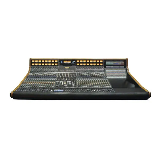
We continue the API Legacy with the Legacy AXS Recording and Mixing Console. Featuring the traditional API analog signal path, the AXS also offers a new and powerful feature set, all at an attractive price for today's studios, artists, engineers and producers. -
Page 8: Configuration Options
Routable Sine-wave oscillator Four USER buttons (toggled contact closures on D-connector) As with all API products, The Legacy AXS Console offers the same exacting craftsmanship featured on all API large format consoles, including a unique 5-year warranty on all parts. -
Page 9: Console Configuration
200 slot may be fitted with one of three dynamic processors or filters. The 500 EQ slot can be fitted with one of four API EQ and filter options or any VPR Alliance approved 500 Series module (except preamps). Any or all of the slots may be left open for future expansion. -
Page 10: Lower 200 Slot
The 500 Series slot on each channel strip is intended to house the channel equalizer (EQ). This 500 Series slot complies with VPR Alliance standards so it can accept any API or VPR approved 500 Series module except preamps. This slot is not designed to house a preamp and does not have a 48v power supply for phantom power. -
Page 11: Master Bucket
Master Bucket The master bucket of the Legacy AXS contains routing and controls for buses, summing, outputs, monitoring and other central console controls. From top to bottom the sections include: • Program Meter Bridge 2500C Stereo Bus Compressor • •... -
Page 12: Channel Signal Path Architecture
After recording, both audio paths can be routed to the program buses to provide additional inputs during mix-down. On the Legacy AXS these audio paths are referred to as the Small Fader path and the Large Fader path. -
Page 13: Multitrack Buses
Multitrack Buses There are twenty-four (24) Multitrack Buses which feed the Active Combining Amplifiers (ACA). The Large Fader or Small Fader can be assigned to any of the 24 Multitrack Buses in the 624 Bus Assignment Module. Only one audio path, Small Fader or Large Fader, can be assigned to the Multitrack Buses at a time. -
Page 14: Small Fader To Multitrack
Default AXS Signal Flow: With no routing buttons engaged, the default channel signal flow is as follows: • Small Fader path: Input: output of the preamp (upper 200 slot) Signal Processing: Lower 200 slot (COMP) Output: Assignable (Direct Output, Multitrack Buses, & Program Buses) •... -
Page 15: Large Fader To Multitrack
In this configuration, the Large Fader path will be used to mix the multitrack returns and must be assigned to a stereo Program Bus for monitoring. Assign the Large Fader path to the desired stereo bus by engaging the STA, STB, or STC and the PAN buttons in the LG section on the 624 Bus Assignment module. -
Page 16: Channel Strip Overview
Channel Strip Overview Upper 200 Slot 212 Microphone Preamplifier (standard configuration) • • Optional 205 Direct Input Module Lower 200 Slot - May be fitted with one of three processor options: 215 Sweep Filter • 225 Compressor/Limiter (standard configuration) • 235 Noise Gate/Expander •... -
Page 17: Channel Input
Model 1608, thus preserving its sonic qualities. This mic-pre articulates high frequencies with great detail, while delivering the big sounding, warm bottom end that API is famous for. Whether it's a live performance or the private setting of a studio session, the 212 will capture every nuance of the moment. -
Page 18: Direct Input
All Discrete Design • The API 205 Direct Instrument Input is specifically designed to accept a guitar or bass direct into it, without any loading on the pickups. The Gain Control is used to normalize the instrument's input level, up to a +4dBu output level. With the use of the unique TONE control, the low end "mud"... -
Page 19: Channel Input Patch Points
Unbalanced • • Blue illumination -20 PAD: Inserts a -20dB pad at the instrument input 100K LOAD: Engages a 100K Ohm input load • Changes the tone of the pickup and tends to darken the high frequency content. GAIN: Sets the preamplifier gain from -40 to +20dB TONE: Adjusts the tonal characteristics of inputs signal Adjusting the TONE control between “Thin”... - Page 20 Patch points for alternate external sources (such as virtual instruments, extra DAW returns, etc.) normalled to the ALT LINE INPUT patch points are not provided in the standard configuration. However, the ALT LINE INPUTs are available via a multi-pin connector on the back of the patch bay to allow normal interfacing to these points.
-
Page 21: Channel Signal Processing
The lower 200 slot is usually designated for dynamic processing, although a filter set can be installed instead. Lower 200 Slot The lower 200 slot is designed to house one of the three API 200 Series signal processor modules: 225 Compressor/Limiter (standard configuration) 235 Noise Gate 215 Sweep Filter The lower 200 slot is typically fitted with an API 225 Compressor/Limiter. -
Page 22: Noise Gate/ Expander
Transformer Output, to +28dBu • The API 235 Noise Gate/Expander has the ability to reduce noise in any type of program. The 235 can open unusually fast, without losing any part of the sound. Its extreme flexibility, repeatable settings, and superb sound make it ideal for all studio, live sound, and broadcast applications. - Page 23 100mS. The 235 makes use of the 2510 and 2520 op-amps and therefore exhibits the reliability, long life, and uniformity which are characteristic of all API products. The controls for the 235 Noise Gate/Expander function as follows:...
-
Page 24: High-Pass, Low-Pass Sweep Filter
500 Series Equalizer Slot The Legacy AXS channel strip is 1.5” inches wide in order to accommodate a VPR Alliance approved 500 Series slot. This slot is designed to house the channel equalizer. The 500 Series EQ slot may be fitted with one of the four API equalizer/filter choices or any VPR Alliance approved 500 Series module, except preamps (the channel signal flow is not designed to accommodate a preamp in this slot.) -
Page 25: Discrete 3-Band Equalizer
Still copied, but never duplicated, the 550A became API's standard channel module EQ when the company began manufacturing consoles in 1971. With virtually all existing units spoken for, popular demand for this EQ resulted in API finally resuming production in 2004. -
Page 26: Discrete 4-Band Eq
"undo" what has been done previously with exact precision. The benefits of the API 550b are most obvious to those who work with EQ on a continuous basis. If major tonal restructuring is required, the extraordinary headroom made possible with API's 2520 Op Amp offers the predictable and warm analog performance, even under duress. -
Page 27: 10-Band Graphic Equalizer
• Based on the original 1969 API 560 EQ Originally conceived for use in API consoles of the '60s and '70s, the 560 is a unique device designed to accomplish tasks that no other EQ can. Extremely fast to set and reset using accurate zero detents, the curve shaping potential of the 560 remains unmatched. -
Page 28: Filter Bank
Traditional API fully discrete circuit design • • Uses API 2520 and 2510 Op-Amps as well as the same discrete transistor buffers used in the famous 550 series equalizers The 565 Filter Bank module has circuits that are true to the musical filters of the famed 215 module found in large format API consoles. -
Page 29: Channel Insert Patch Points
Channel Insert Patch Points A set of INSERT SEND and INSERT RETURN patch points for each fader path (Large and Small) are provided in the Channel patch bay. LARGE INSERT SEND: Insert Send from Large Fader path Always active Pre-fader, post-EQ LARGE INSERT RETURN: Insert Return to the Large Fader path Patched signal is inserted in the Large Fader path when the INS button is engaged... -
Page 30: Channel Faders And Controls
Channel Faders and Controls 968 Input Module The illustration above shows the 968 Input Module with a brief description of each control. This serves as a quick reference guide. A more detailed description of each control follows. L e g a c y A X S A P I... -
Page 31: Small Fader Path Controls
Small Fader Path Controls The 968 Small Fader audio path is a complete audio channel designed to serve the following functions: • Routing microphone and instrument inputs to a multitrack recorder OR monitor mix during multitrack recording • Additional inputs during mix down •... - Page 32 The SAFE button protects the Small Fader from being muted when the Solo-In-Place function is active and another channel is soloed Protects from global changes to channel routing (input and compressor) Illuminates when engaged Ø (Phase Reverse): Inserts a polarity inverter into the Small Fader path Illuminates when engaged PAN: This is the pan pot control for the Small Fader path -2.5dB pan law...
-
Page 33: Large Fader Path And Channel Routing Controls
Large Fader Path and Channel Routing Controls The 968 Large Fader audio path is the primary audio channel designed to serve the following functions: Primary signal path during mixing with 100mm, automated fader Monitor mix during multitrack recording Routing microphone and instrument inputs to a multitrack recorder Retuning effects, virtual tracks, and other sources during mix-down The Large Fader path is fed from the Line Input by default. - Page 34 The -6dB Line Pad will reduce distortion and increase headroom in the audio path when the level from the multitrack recorder return is hot enough to overload the Line Input Illuminates when engaged COMP LRG (Compressor to Large Fader): Moves the 200 slot processor into the Large Fader path •...
-
Page 35: Large Fader
Large Fader AUTOMATION MUTE: (Channel Mute) Cuts the Large Fader audio output The MUTE button is the on/off switch for the Large Fader Activates the 968 MUTE button Not activated by the 968 MUTE button Controlled by automation • Illuminates in red when engaged LARGE FADER: Controls the output level of the Large Fader audio path Full-size 100mm resistive fader +10dB of gain... -
Page 36: Auxiliary Sends
Auxiliary Sends The Legacy AXS console provides a powerful Auxiliary Send system that provides a complete set of options for Cue Sends (headphone feeds) and Effects Sends. There are twelve (12) Auxiliary Buses, all of which may be used simultaneously. -
Page 37: Channel Vu Meters
NOTE: Aux Sends 5-12 can be fed from the Small Fader path by engaging the AUX 5-12 button in the 968 Small Fader controls. Stereo Aux Sends 7-12 Aux Sends 7-12 are organized as three stereo Aux Sends that may be used as a cue sends for headphones during recording or effects sends during mix down. -
Page 38: Large Fader And Small Fader Peak Indicators
The METER SELECT controls for the channel VU Meters function as follows: VU LRG (Large Fader): Routes the Large Fader path input to the VU meters • Illuminates when engaged VU SM (Small Fader): Routes the Small Fader path input to the VU meters •... -
Page 39: Channel Output Routing And Bus Assignment
Channel Output Routing and Bus Assignment The output of each audio path (Small Fader and Large Fader) may be routed to the following destinations: Channel Direct Output Multitrack Buses 1-24 Stereo Program Bus A Stereo Program Bus B Stereo Program Bus C IMPORTANT NOTE: If no output assignments have been made, the output of the Large Fader will feed the Channel Direct Output and the Small Fader will not be routed anywhere. -
Page 40: Bus Assignment Module
624 Bus Assignment Module The 642 Bus Assignment Module provides comprehensive output signal flow routing for both fader paths and allows the assignment of the Large Fader and Small Fader path outputs to the following buses: Multitrack Buses 1-24 Stereo Program Bus A Stereo Program Bus B Stereo Program Bus C Only one fader path at a time (Large or Small) can feed the Multitrack buses (1-... -
Page 41: Channel Patch Bay
Channel Patch Bay The Legacy AXS has 14 patch points associated with channel signal flow. These points are located in the Channel patch bay. The 14 channel patch points are as follows: MIC TIE-LINE MIC PREAMP INPUT (upper 200 slot mic preamp in) - Page 42 Breaking input: Inserted patch cord will replace normalled • connection Not used with 205 Direct Input Module • CAUTION: The MIC PREAMP INPUT patch point will carry 48-Volt phantom power when the 48V button is engaged on the associated 212 Mic Preamp. Care should be used and 48V should be always be disengaged when patching to these points.
- Page 43 DIRECT OUTPUT: Channel Direct Output (as assigned) Fed post-fader from the Large Fader by default Half-normalled to the MULTITRACK INPUT • Outputs split if patched MULTITRACK INPUT: Connection to multitrack recorder inputs Half-normalled from the DIRECT OUTPUT Breaking input: Inserted patch cord will replace normalled connection NOTE: The multitrack recorder may alternately be fed from the Multitrack Buses by patching the BUS OUTPUT patch points to the MULTITRACK INPUT patch points.
-
Page 44: Master Bucket
Master Bucket The AXS master bucket accommodates all the central facilities modules that work in concert with the channels to provide a complete, flexible, comprehensive recording and production system. Main Stereo Meters Indicators 2500C Stereo Bus Compressor Stereo Program Bus Masters Multitrack Auxiliary Masters Bus Masters... -
Page 45: Master Channel Routing Controls
The Legacy AXS master bucket provides a comprehensive suite of master controls, facilities, and features that address all the needs of modern audio production. These facilities include: Master Channel Routing Controls • • 6 Assignable Stereo Returns 3 Stereo Program Bus Masters and Master Faders (A, B, C) •... - Page 46 0dB SM (Small Fader): Engages a 0dB fader bypass for Small Faders globally • Illuminates when engaged L e g a c y A X S A P I...
-
Page 47: Stereo Return Modules 1-6
Stereo Return Modules 1-6 Every Legacy AXS is equipped with six Stereo Return modules, located in the master bucket. The six Stereo Returns are designed to provide extra capacity and flexibility during mixing and support techniques such as returning stereo stems to a mix,... -
Page 48: Stereo Return Signal Flow
Stereo Return Signal Flow The diagram below shows the basic Stereo Return signal flow from input to the stereo Program Masters/Grand Master and Direct Output. In interest of space, patch points for only 3 of the 6 Stereo Returns are shown. The Stereo Returns have two input options: Line-Level: STEREO RETURN INPUT patch points •... -
Page 49: Stereo Return Controls
A balanced stereo Insert with an in/out switch is provided for each Stereo Return. Engage the INS button to route the Insert Return to the Stereo Return signal path. Stereo Return Insert patch points are available on the System patch bay. In addition to Stereo Program Bus and Grand Master output assignments, the Stereo Returns have Direct Outputs that are available in the System patch bay (STEREO RETURN DIRECT OUT). -
Page 50: Stereo Return Patch Points
Illuminates in red when engaged Stereo Fader (not shown): Controls the output level of the Stereo Return output Full-size 100mm resistive fader +10dB of gain -∞ dB of attenuation Unity gain when set to 0dB Controlled by automation Meter: Displays Stereo Return output level •... -
Page 51: Stereo Program Bus Masters And Master Faders
Stereo Program Bus Masters and Master Faders The Legacy AXS is equipped with three stereo Program Buses (STA, STB, and STC) that are accessible from channels and the six Stereo Returns. The output of each stereo Program Bus “Active Combining Amplifier”... -
Page 52: 624Sm Stereo Program Master Module
The diagram on the previous page shows the basic Stereo Program Bus signal flow from channel Program Bus assignment, through the stereo Masters and Grand Master, to the 2Track Inputs. 624SM Stereo Program Master Module The 624SM Stereo Program Master Module contains the controls for the three stereo Program Buses as well as the stereo Grand Master. -
Page 53: 2500C Stereo Bus Compressor
2500C Stereo Bus Compressor The Legacy AXS is equipped with a 2500C Stereo Bus Compressor. This compressor is available only on patch, but can be routed to STA, STB, STC, or GM via insert. See the user guide in the appendix. -
Page 54: Stereo Program Master Patch Points
The Main Meters have two controls in the METER SELECT area of the Master Section. The METER SELECT controls for the Main Meters function as follows: MAIN VU 0=+10: Inserts a -10dB pad before the Main Meter inputs • Use to meter high level signals Illuminates when engaged •... - Page 55 NOTE: The 2500C Stereo Bus Compressor must be patched to be used. L e g a c y A X S A P I...
-
Page 56: Multitrack Buses
Multitrack Buses There are twenty-four (24) Multitrack Buses. Multitrack Bus assignments are made using the 624 Bus Assignment module in each channel. Multitrack Buses may be fed from either the Small Fader path or Large Fader path, but not both simultaneously. -
Page 57: Multitrack Patch Points
Each Multitrack Bus Master has a gain control and trim control. These controls feed the BUS OUTPUT patch points 1-24 in the System patch bay. Controls for the 624M Multitrack Bus Masters are as follows: ON (on/off switch): On/off switch for the Multitrack Bus outputs Illuminates when engaged •... -
Page 58: Auxiliary Buses And Masters
Auxiliary Buses and Masters The Legacy AXS console provides a powerful Auxiliary Send system with a variety of options for headphone cue sends, effects sends, and other applications. There are twelve (12) Auxiliary Buses and Masters. While all the Aux Buses are technically mono, like... -
Page 59: Auxiliary Masters 1-12
Auxiliary Masters 1-12 Auxiliary Bus Masters 1-12 are located above the Stereo Returns in the 265 Aux Master module. Each Aux Master is the output control for the corresponding Auxiliary Bus. Aux Bus Masters 1-6 Aux Bus Masters 7-12 provide output level provide output level control for mono Aux control for stereo Aux... - Page 60 To create normalled connections to headphone cue systems and effects devices, through external effects processors, and back to the program buses for mixing, the Legacy AXS provides AUX DEVICE INPUT and AUX DEVICE OUTPUT patch points to. The AUX DEVICE INPUT (CUE AMP) patch points are half-normalled from the AUX SEND OUTPUT (CUE) patch points.
- Page 61 L e g a c y A X S A P I...
-
Page 62: Monitor Control
Monitor Control The Legacy AXS console provides comprehensive control room and studio monitor control facilities. Features include: Control room stereo and surround monitoring Control room monitor systems: Two stereo ALT systems with independent level One MAIN stereo/5.1 surround system Individual monitor cuts... -
Page 63: Control Room Monitor Source Selection (Monitor Select)
Control Room Monitor Source Selection (MONITOR SELECT) The MONITOR SELECT section contains selectors for seven internal console (PGM MNTR) or six external (PLAY MNTR) sources for the control room monitor systems. This section also contains the main Control Room monitor level control (C/R LEVEL). -
Page 64: Control Room Speaker Selection And Controls
Control Room Speaker Selection and Controls The Legacy AXS console provides support for three (3) control room monitoring systems, with a main C/R LEVEL control and independent level trims for ALT1 and ALT2. The Left and Right MAIN monitors are used primarily for stereo monitoring. However, the MAIN monitors support a 5.1 monitor system for playback of... -
Page 65: Studio Monitoring
MONO: Sums the Left and Right speaker feeds to mono • Illuminates when engaged ALL CUT: Cuts the feed to all control room speaker feeds Illuminates when engaged • Studio Monitoring Studio monitor feeds are provided for two (2) studio monitor systems. There is one studio monitor output that normally feeds the main studio monitor system. - Page 66 CAUTION: Exercise great care when patching into any of the Amplifier Input (AMP IN) patch points. There is no level control between these patch points and the inputs to the monitor system amplifiers. Patching unattenuated signals into these patch points can result in very loud output from the Control Room monitor system.
-
Page 67: Solo Modes And Controls
Solo Modes and Controls Solo Modes The Legacy AXS provides five solo modes: After-Fader Listen (AFL) Pre-Fader Listen (PFL) Pre-Fader Listen 2(PFL 2) Solo-In-Place (SIP) Mix-Over-Solo After-Fader Listen (AFL) is the default Solo mode (no buttons engaged). Solo modes are selected using the SOLO controls in the Master Section. The selected solo mode is activated when a channel or Stereo Return SOLO button is engaged. -
Page 68: Solo Controls
Solo Controls SOLO controls operate as follows: MIX OVER: Activates the “Mix Over Solo” function • Enables mixing of the Solo Bus and the selected control room monitor source Illuminates when engaged MIX OVER SOLO: Level control for the “Mix Over Solo” function Adjusts the balance between the Solo Bus and the control room •... - Page 69 LATCH: Activates the Latch solo mode on channels and Stereo Returns Only one SOLO button may be engaged at once • The SOLO button will remain engaged when pressed and released • The active SOLO button will be disengaged by pressing a it second time •...
-
Page 70: Talkback
Talkback The Legacy AXS console provides a comprehensive Talkback system with flexible routing and options. The control room Talkback facility has two inputs: a microphone mounted on a “gooseneck” in the console Master Section and an EXT TBK microphone input that appears on the patch bay. These microphones provide control room communication to a variety of destinations. -
Page 71: Talkback Patch Points
AUX (TALK): Routes the output of the Talkback Mic preamp to Auxiliary Masters Useful for talking to headphone cues sends The T/B button must be engaged on the Aux Master for Talkback to be passed to its output • Can be activated from the T/B ALL button •... -
Page 72: Vu Meters And Peak Indicators
VU Meters and Peak Indicators The Legacy AXS console provides the following displays for monitoring levels: Main stereo VU meters Channel VU meters Channel peak indicators 200 Module LED meters Stereo Return LED meters Auxiliary Master LED meters The following 200 Series modules have built-in LED output meters:... -
Page 73: Channel Peak Indicators
Stereo Program Buses A, B, C, and Grand Master (meters 25-32) The feed to the channel VU meter is determined by the selection made using the VU SELECT controls in the Master Section. These selections are global and apply to all channel VU Meters. The METER SELECT controls for the channel VU meters function as follows: VU LRG (Large Fader): Routes the Large Fader path input to the VU meters •... -
Page 74: Stereo Return Meters
control room Monitor Source is replaced with the output of the Solo Bus and the Solo Bus is displayed on the LEFT and RIGHT Main Meters (SOLO). The Main Meters have two controls in the METER SELECT area of the Master Section. The METER SELECT controls for the Main Meters function as follows: MAIN VU 0=+10: Inserts a -10dB pad before the Main Meter inputs. -
Page 75: Patch Bay
Patch Bay All API console patch bays provide extended access throughout the audio signal flow. In the standard configuration 12 patch points are provided for every channel and options for additional points are available. A comprehensive set of patch points that support buses, masters, monitors, and central facilities is also provided. -
Page 76: Channel Patch Bay
Channel Patch Bay The Legacy AXS has 14 patch points associated with channel signal flow. These points are located in the Channel patch bay. The 14 channel patch points are as follows: MIC TIE-LINE MIC PREAMP INPUT (upper 200 slot mic preamp in) - Page 77 MIC PREAMP INPUT: 212 Mic Preamp inputs • Balanced, low-impedance, mic-level input Full-normal from MIC TIE-LINE patch points • • Breaking input: Inserted patch cord will replace normalled connection • Not used with 205 Direct Input Module CAUTION: The MIC PREAMP INPUT patch point will carry 48-Volt phantom power when the 48V button is engaged on the associated 212 Mic Preamp.
-
Page 78: System Patch Bay
LARGE INSERT RETURN: Insert Return to the Large Fader path Patched signal is inserted in the Large Fader path when the INS button is engaged Pre-fader, post-EQ DIRECT OUTPUT: Channel Direct Output (as assigned) Fed post-fader from the Large Fader by default Half-normalled to the MULTITRACK INPUT Outputs split if patched •... -
Page 79: Stereo Return Patch Points
Stereo Return Patch Points The following section outlines Stereo Return patch points. AUX DEVICE OUTPUT: Stereo output connections for external devices Half-normalled to the STEREO RETURN INPUT Outputs split if patched STEREO RETURN INPUT: Balanced, line-level, low-impedance Half-normalled from the AUX DEVICE OUTPUT •... -
Page 80: 2500C Stereo Bus Compressor Patch Points
GM INSERT SEND (Grand Master): Insert Send from the stereo Grand Master Always active Pre-fader GM INSERT RETURN (Grand Master): Insert Return to the stereo Grand Master Patched signal is inserted in the Program Master signal flow when the INS button is engaged Pre-fader GM OUTPUT (Grand Master): Main outputs for the stereo Grand Master •... - Page 81 To create normalled connections to headphone cue systems and effects devices, through external effects processors, and back to the program buses for mixing, the Legacy AXS provides AUX DEVICE INPUT and AUX DEVICE OUTPUT patch points to. The AUX DEVICE INPUT (CUE AMP) patch points are half- normalled from the AUX SEND OUTPUT (CUE) patch points.
- Page 82 L e g a c y A X S A P I...
-
Page 83: Monitor System Patch Points
Monitor System Patch Points Control Room Monitor Patch Points MAIN CR MNTR OUT (Main Control Room Monitor Outputs): Outputs to the MAIN control room monitor system Half-normalled to MAIN CR MNTR AMP INPUT Outputs split if patched MAIN CR MNTR AMP INPUT (Main Control Room Monitor Amplifier Inputs): Inputs to the main control room monitor amplifiers Half-normalled from MAIN CR MNTR OUT •... -
Page 84: Talkback Patch Points
2 TRACK MNTR IN (2-Track Monitor Inputs): Feeds the 2T1, 2T2, 2T3, 2T4 monitor playback selectors Half-normalled from 2T1 – 2T4 OUT Patching to these points will replace the feed to the 2 track monitor selectors with the patch cord signal 6T1-6T2 OUT (6-Track Outputs 1-2): Returns from the external 5.1 surround playback source outputs Left, Right, Left Surround, Right Surround,... -
Page 85: Appendix
The GAIN pot can be either switched IN for manual gain control, or it can be left OUT and the 25OO will bring the output level up and down automatically, keeping the signal at the same level regardless of where the THRESH or RATIO controls are set. This is the same as the API 525 Ceiling control. - Page 86 Just to the right of the VU meters, there is a set screw adjustment. This adjustment is to rock or tilt the signal left or right when in the auto gain mode, allowing subtle corrections in the stereo image if it is off center when compressing. This control only affects the image when the 25OO is above the threshold, and does not do anything when the signal is not being compressed.
- Page 87 Compressor Section L e g a c y A X S A P I...
- Page 88 Tone Section L e g a c y A X S A P I...
- Page 89 Link and Output Section L e g a c y A X S A P I...
- Page 90 Meter and Trim Section When in doubt start with all the controls straight up! L e g a c y A X S A P I...
-
Page 91: Setup Documents
Setup Documents 2500C Setup Sheet L e g a c y A X S A P I... -
Page 92: Setup Sheet
205 Setup Sheet L e g a c y A X S A P I... -
Page 93: Setup Sheet
212 Setup Sheet L e g a c y A X S A P I... -
Page 94: Setup Sheet
215 Setup Sheet L e g a c y A X S A P I... -
Page 95: Setup Sheet
225 Setup Sheet L e g a c y A X S A P I... -
Page 96: Setup Sheet
235 Setup Sheet L e g a c y A X S A P I... -
Page 97: Setup Sheet
550A Setup Sheet L e g a c y A X S A P I... -
Page 98: Setup Sheet
550b Setup Sheet L e g a c y A X S A P I... -
Page 99: Setup Sheet
560 Setup Sheet L e g a c y A X S A P I... -
Page 100: Setup Sheet
624 Setup Sheet L e g a c y A X S A P I... -
Page 101: Setup Sheet
968 Setup Sheet L e g a c y A X S A P I... - Page 103 8301 Patuxent Range Road Jessup, MD 20794 USA 301-776-7879 http://www.apiaudio.com L e g a c y A X S A P I...
Need help?
Do you have a question about the Legacy AXS and is the answer not in the manual?
Questions and answers