
Related Manuals for API The BOX


Summary of Contents for API The BOX
- Page 1 Recording & Mixing Console Operator’s Manual 10-01-13 Written for Automated Processes Incorporated by Dan Pfeifer 2013...
-
Page 2: Table Of Contents
API “The BOX” Operator’s Manual Table of Contents Overview Input Channels 1-4 Preamp Filter, Routing, and Meter 2.2.1 High-Pass Filter 2.2.2 Compressor Routing 2.2.3 Insert 2.2.4 Output Routing and Pan-Pot 2.2.5 Meter and Meter Routing Fader, Mute, Solo, and Solo-Safe 550A Equalizer –... - Page 3 Application Guide 14.1 Recording 14.1.1 Input Channels While Recording 14.1.2 Summing Inputs While Recording 14.1.3 Using DAW Mixes While Recording 14.1.4 Cue and Headphones 14.1.5 Talkback 14.2 Mixing in “The BOX” 14.2.1 Program Bus Compression 14.2.2 Effect Sends and Returns...
- Page 4 API “The BOX” Operator’s Manual APPENDIX Limited Warranty and Service Information Block Diagram DB-25 Pin-out Diagrams...
-
Page 5: Important Safety Instructions
API “The BOX” Operator’s Manual Important Safety Instructions Please read these instructions Keep this Information in a safe place Do not use this console near water Clean only with a dry cloth Do not block any ventilation openings Do not install near any heat sources such as radiators, heat registers, stoves, or other devices... -
Page 6: Overview
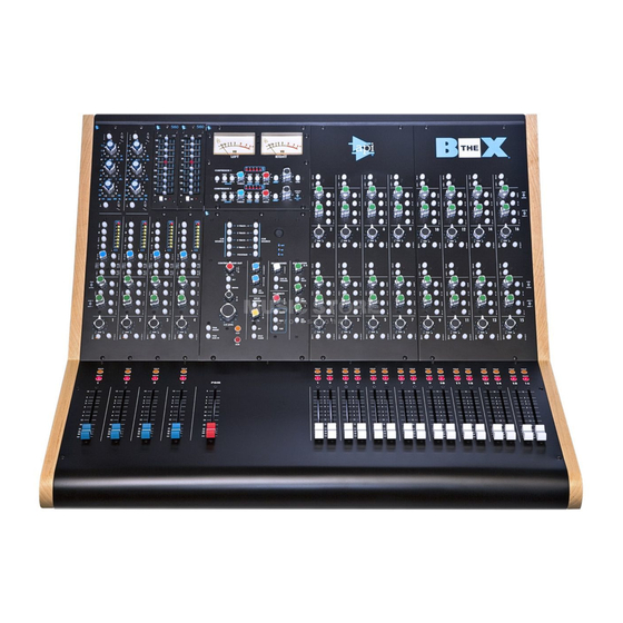
BOX” handles all the functions needed for production not provided by most DAWs, including a preamp, input signal processing, high-quality mix bus, cue sends with talkback, monitor control, and more, without the redundant capacities of larger consoles. Most importantly, “The BOX” provides the legendary “all discrete” API sound in an efficient, cost-effective package. Features Two (2) input channels with mic/instrument/line preamp, HP filter, &... - Page 7 • Console Layout For recording, “The BOX” provides four (4) input channels. Channels 1 & 2 are equipped with preamp, filter, built-in 550A equalizer, insert, assignable compression, and output routing. Channels 3 & 4 provide the same features, but are each equipped with an API 500 series slot...
- Page 8 In addition, the master section contains two (2) 527 compressors that can be assigned to the input channels when recording and the program bus when mixing. To help assure reliability and longevity, “The BOX” is built to the same exacting API quality standards as our Vision, Legacy Plus, and 1608 consoles.
-
Page 9: Input Channels
API “The BOX” Operator’s Manual Input Channels 1-4 “The BOX” provides four (4) input channels that are designed primarily for recording, but can be used as additional channels while mixing. All four channels are identical except for equalization. Channels 1 & 2 have a built-in 550A equalizer. - Page 10 API “The BOX” Operator’s Manual The basic signal flow through the input channels module is as follows: Preamplifier ⇒ compressor ⇒ EQ/500 slot ⇒ insert ⇒ fader/mute ⇒ filter ⇒ output The compressor can be moved to after the insert (COMP POST) to yield: Preamplifier ⇒...
- Page 11 API “The BOX” Operator’s Manual Preamplifier The preamplifier section of the input channels provides a fully featured input stage that’s identical to the channel preamps in the API 1608. The preamp can accept the following input signals: Microphone • Instrument •...
- Page 12 API “The BOX” Operator’s Manual Preamp Controls: No switches engaged: LINE INPUT is selected by default 48V (Phantom Power): Applies 48 volt phantom power to the MIC INPUT XLR connector for use with condenser mics and active DI boxes Illuminates in red when engaged •...
- Page 13 API “The BOX” Operator’s Manual Rear Panel Preamp Connections All four input channels have the same preamp input connections on the rear panel. INSTRUMENT INPUT: ¼” tip-sleeve, unbalanced, high- impedance • MIC must be engaged to use this input •...
-
Page 14: Filter, Routing, And Meter
API “The BOX” Operator’s Manual Filter, Routing, and Meter Input channels provide a 50Hz high-pass filter, an 8-segment LED full-scale meter, and several routing possibilities. Routing possibilities include: Compressor assignment to input channels • Compressor placement in signal flow •... -
Page 15: Compressor Routing
Operator’s Manual 2.2.2 Compressor Routing “The BOX” includes two API 527 compressor/limiters in the center section of the console. These compressors are assigned to the program bus by default for mixing, but can be routed to the input channels while recording. -
Page 16: Insert
API “The BOX” Operator’s Manual 2.2.3 Insert A balanced insert with switch is provided on each input channel. INS (insert): Routes the insert return to the signal path The insert return is active only when the INS switch is engaged •... -
Page 17: Output Routing And Pan-Pot
API “The BOX” Operator’s Manual 2.2.4 Output Routing and Pan-Pot Direct Output Each input channel has a direct output intended to feed a DAW analog input while recording. The direct output is fed post-fader/mute by default, but can be fed by the preamp output. -
Page 18: Meter And Meter Routing
API “The BOX” Operator’s Manual 2.2.5 Meter and Meter Routing Input channels are equipped with an 8-segment LED full-scale meter. The meter displays the post-fader output from the channel by default, but can be switched to display the output of the preamp. A calibration trim-pot is provided so 0dBFS on the meter matches 0dBFS in the connected DAW. -
Page 19: Fader, Mute, Solo, And Solo-Safe
API “The BOX” Operator’s Manual Fader, Mute, Solo, and Solo-Safe The fader module with blue fader caps contains the faders, MUTE and SOLO switches for input channels 1-4. These faders are the primary output level controls for the input channels. - Page 20 API “The BOX” Operator’s Manual INPUT FADER: Primary output level control 100mm full-size audio-taper fader • -∞dB to +12dB range • 0dB is unity gain • Blue fader cap • The input channel MUTE and SOLO switches are located just above the fader.
-
Page 21: 550A Equalizer - 500 Slot
API “The BOX” Operator’s Manual 550A Equalizer – 500 Slot Input channels 1 & 2 provide semi-parametric equalization using the legendary API 550A EQ. Input channels 3 & 4 provide two (2) 500 slots for modules that conform to the standards set forth by the API VRP Alliance. This combination provides the classic... - Page 22 API “The BOX” Operator’s Manual The combination of Walker's incomparable 2520 op-amp, and his "Proportional Q" circuitry gives the 550A user an uncomplicated way to generate acoustically superior equalization. With the long-awaited reissue of this unit, an EQ that has had such a part in the history of recording is continuing to make history in today's music.
- Page 23 API “The BOX” Operator’s Manual IN: Places the EQ in the signal path when engaged Silent operation • Illuminates when engaged • High Frequency: Center Frequency (knob & blue numbers): • 2.5kHz, 5kHz, 7kHz, 10kHz, 12.5kHz, 15kHz, 20kHz Boost/Cut (ring & white numbers): •...
-
Page 24: Api 500 Series Slot
API “The BOX” Operator’s Manual 2.4.2 API 500 Series Slot Input channels 3 & 4 are each equipped with an API 500 series slot that can accept any module that conforms the standards set forth by the API VPR Alliance. These 500 series slots are built to power and interface any API or JDK Audio 500 series module. -
Page 25: Auxiliary/Cue Sends
API “The BOX” Operator’s Manual Auxiliary/Cue Sends “The BOX” is equipped with four (4) auxiliary sends fed by two (2) mono auxiliary sends (1/2), and one (1) stereo auxiliary/cue send (3/4). Each pair of sends has pre/post-fader routing and an on/off switch. The stereo aux send (3/4) can be routed to feed the stereo cue bus instead of aux buses 3 &... -
Page 26: Mono Aux Sends
API “The BOX” Operator’s Manual 2.5.1 Mono Aux Sends 1/2 AUX 1 and AUX 2 are mono auxiliary sends that feed aux buses 1 and 2. These sends are commonly used as effects sends, but can be used for additional headphone feed or other purposes. -
Page 27: Stereo Cue Sends
Operator’s Manual 2.5.3 Stereo Cue Sends In addition to auxiliary buses 1-4, “The BOX” is equipped with a separate stereo cue bus, cue master, and balanced output. When recording, the primary purpose of this cue system is the creation of a headphone feed, so talkback and other sources can be routed to the cue master. -
Page 28: Input Channel Rear Panel Connections
API “The BOX” Operator’s Manual Input Channel Rear Panel Connections The rear panel provides a comprehensive flexible input channel connections. Connections include: Preamp inputs (mic, • instrument, and line) Insert sends and returns • Direct outputs / preamp • outputs Preamp output / 500 slot •... -
Page 29: Input Channel Insert Connections
API “The BOX” Operator’s Manual 2.6.2 Input Channel Insert Connections All insert sends and returns are balanced, low-impedance, line-level signals routed via ¼” tip-ring-sleeve jacks on the rear panel. The insert send is post-EQ on channels 1 & 2. EQUALIZER OUT- INSERT SEND: ¼” tip-ring- sleeve, balanced, low-impedance, line-level INSERT RETURN: ¼”... -
Page 30: Input Channel Direct And Preamp Output Connections
API “The BOX” Operator’s Manual 2.6.3 Input Channel Direct and Preamp Output Connections The DIRECT OUTPUTS / PRE OUTPUTS connector carries direct or preamp outputs from input channels 1-4, as well as the insert send from input channels 1 & 2 and the preamp outputs from input channels 3 &... -
Page 31: Summing Input Channels
API “The BOX” Operator’s Manual Summing Input Channels 1-16 “The BOX” provides sixteen (16) summing input channels (summing inputs) that optimized for mixing in a DAW environment. sixteen summing inputs are identical. Along with their associated faders, each summing input... - Page 32 API “The BOX” Operator’s Manual 2-Channel Summing Input Strip Sections...
-
Page 33: Input Routing
API “The BOX” Operator’s Manual Summing Input Controls Input Routing Summing inputs accept balanced, low-impedance, line-level signals from the SUMMING INPUTS 1-8 and SUMMING INPUTS 9-16 DB-25 connectors on the rear panel. This line input is the primary summing channel input. Other than the insert return, it’s the only input available. -
Page 34: 0Db (Unity Gain)
DAW returns on a console. To preserve the balance of automated tracks coming from the DAW, “The BOX” includes a fader bypass (“0dB” switch) on the summing inputs to route these tracks directly to the program bus at unity gain. -
Page 35: Fader, Mute, Solo, And Solo-Safe
API “The BOX” Operator’s Manual Fader, Mute, Solo, and Solo-Safe The fader modules with white fader caps contain the faders, MUTE and SOLO switches for summing inputs 1-16 (1 & 2 shown). The summing input fader controls for each pair of channels are arranged in a side-by- side configuration. - Page 36 API “The BOX” Operator’s Manual SUMMING FADER: Primary output level control 100mm full-size audio-taper fader • -∞dB to +12dB range • 0dB is unity gain • White fader cap • The summing input MUTE and SOLO switches are located just above the fader.
-
Page 37: Output Routing And Pan-Pot
API “The BOX” Operator’s Manual Output Routing and Pan-Pot Each summing input can be routed to the program bus via the PGM assignment switch. The program bus is fed post-fader/mute and pan-pot. Program Bus Assignment PGM (Program): Assigns the summing channel output to the program... -
Page 38: Auxiliary Sends
API “The BOX” Operator’s Manual Auxiliary Sends “The BOX” is equipped with four (4) auxiliary sends fed by two (2) mono auxiliary sends (1/2), and one (1) stereo auxiliary/cue send (3/4). Each pair sends pre/post-fader routing and an on/off switch. The stereo aux send (3/4) can be routed to feed the stereo cue bus instead of aux buses 3 &... -
Page 39: Stereo Aux Sends
• 3.4.3 Stereo Cue Sends In addition to auxiliary buses 1-4, “The BOX” is equipped with a separate stereo cue bus, cue master, and balanced output. When recording, the primary purpose of this cue system is the creation of a headphone feed, so talkback and other sources can be routed to the cue master. -
Page 40: Summing Input Rear Panel Connections
API “The BOX” Operator’s Manual Summing Input Rear Panel Connections The rear panel provides a comprehensive and flexible set of summing input connections. Connections include: Line inputs • Insert sends and returns • 3.5.1 Summing Input Line Input Connections The line inputs for the sixteen summing inputs are distributed across two DB-25 connectors. -
Page 41: Summing Input Insert Connections
API “The BOX” Operator’s Manual 3.5.2 Summing Input Insert Connections All insert sends and returns are balanced, low-impedance, line-level signals routed via ¼” tip-ring-sleeve jacks on the rear panel. The insert send is fed immediately after the input on summing inputs 1-16. -
Page 42: Master Section
API “The BOX” Operator’s Manual Master Section The master section of “The BOX” is equipped with a comprehensive set of components needed to support a wide range of recording and mixing applications. - Page 43 API “The BOX” Operator’s Manual The master section includes the following facilities: Stereo program bus master: PGM SUM IN, PGM INSERT, and master fader • Auxiliary bus masters: AUX MASTER 1-4 • Cue master: CUE • Solo master: SOLO MASTER •...
-
Page 44: Stereo Program Master
Channels ⇒ program bus ⇒ compressor ⇒ insert ⇒ master fader ⇒ output Program Sum Inputs “The BOX” is equipped with a stereo pair of external inputs that sum with the program bus. This is useful for adding an external stereo source, such as a sub-mix to the program bus in “The BOX.”... -
Page 45: Program Bus Compression
Operator’s Manual Program Bus Compression “The BOX” includes two API 527 compressor/limiters in the center section of the console. These compressors are assigned to the program bus by default for mixing, but can be routed to the input channels while recording. -
Page 46: Program Bus Inserts
API “The BOX” Operator’s Manual Program Bus Inserts The program bus is equipped with a stereo balanced insert with switch. PGM INSERT (program insert): Routes the program insert return to the signal path The program insert return is active only when the PGM INSERT •... -
Page 47: Program Bus Outputs
API “The BOX” Operator’s Manual Program Bus Outputs “The BOX” is equipped with stereo, balanced, low-impedance line-level program outputs terminated with XLR connectors. PROGRAM BUS OUTPUT (LEFT & RIGHT): 3-pin male XLR, balanced, low-impedance, line-level Located post-master fader • Program Bus Rear Panel Connections... -
Page 48: Program Sum Input Connections
API “The BOX” Operator’s Manual 5.6.1 Program Sum Input Connections PROGRAM SUM INPUT (LEFT & RIGHT): 3-pin female XLR, balanced, low-impedance, line-level Located pre-insert and compressor • 5.6.2 Program Bus Outputs PROGRAM BUS OUTPUT (LEFT & RIGHT): 3-pin male XLR, balanced, low-impedance, line-level Located post-master fader •... -
Page 49: 527 Compressors
Operator’s Manual 527 Compressors “The BOX” is equipped with two API 527 compressor/limiters that are located above the master section of the console. These compressors are assigned to the program bus by default for mixing, but can be routed to the input channels while recording. -
Page 50: Input Channel Routing
Audio circuit uses the 2520 discrete op-amps • The 527 compressors in “The BOX” are identical to the API 527 modules and the 527 in API’s “The Channel Strip,” with the exception of the gain reduction meter and the a side-chain input on the TCS. -
Page 51: Program Bus Routing & Link
API “The BOX” Operator’s Manual Program Bus Routing & Link To use the compressors while mixing, they need to be assigned to the program bus, with Compressor 1 assigned to Left side of the program bus and Compressor 2 assigned to the Right. The compressors are located after the PROGRAM SUM INPUT and before the insert send. -
Page 52: Compressor Controls
API “The BOX” Operator’s Manual Compressor Controls The 527 compressor provide a complete set of functions and parameters, including the ® unique THRUST side-chain filter. 6.3.1 Compressor Routing Controls IN: Places the compressor in the signal path when engaged Silent operation •... -
Page 53: Compressor Configuration Controls
API “The BOX” Operator’s Manual 6.3.2 Compressor Configuration Controls Knee KNEE (SOFT-HARD): Toggles between soft and hard knee compression Changes the shape of the compression curve at the rotation point • SOFT is selected when not engaged • Hard is selected when engaged •... - Page 54 API “The BOX” Operator’s Manual Compressor Circuit Topologies The 527 compressors can be set to operate in two circuit topologies: OLD: Feed-back: The RMS detector receives the signal from after the VCA • NEW: Feed-forward: The RMS detector receives the signal from before the VCA •...
- Page 55 API “The BOX” Operator’s Manual ® THRUST ® The 527 compressor includes API’s patented THRUST circuit that can be switched in ® or out as needed. This places the THRUST filter before the RMS detector that decreases the compressor’s reaction to low frequency content. The result is a noticeable increase of punch and low frequencies, but a uniformly compressed signal.
-
Page 56: Compressor Parameter Controls
API “The BOX” Operator’s Manual ® THRUST filter response Stereo Link LINK: Activated DC link between compressions 1 and 2 Stereo compression when engaged • Sums the DC gain reduction voltage of both units • Illuminates when engaged • NOTE: Both compressors must be IN, assigned to the program bus, with the link engaged to apply proper stereo mix compression. -
Page 57: Gain Reduction Meter
API “The BOX” Operator’s Manual Attack and release times are fully variable on the 527 compressor and share a dual-concentric potentiometer for control. Attack time is adjusted using the outer ring of the pot and Release time is adjusted using the inner knob. -
Page 58: Auxiliary Masters
Operator’s Manual Auxiliary Masters “The Box” is equipped with four (4) auxiliary buses arranged as two mono buses (1 and 2) and one stereo bus (3/4). Accordingly, the console is fitted with matching aux masters in the same configuration. The aux system provides effects sends while mixing, additional headphone feeds while recording, and extra routable sends for other applications. -
Page 59: Aux Master Solos
API “The BOX” Operator’s Manual 7.1.1 Aux Master Solos Each aux master can be soloed using either the AFL or PFL solo mode. When AFL is the current solo mode, mono aux masters 1 & 2 feed the LEFT and RIGHT sides of the stereo AFL solo bus in mono. -
Page 60: Cue Master
Operator’s Manual Cue Master In addition to the four auxiliary buses, “The BOX” is equipped with a separate stereo cue bus and associated cue master. The cue system supports headphone feeds while recording and can be used as an alternate stereo effects send while mixing. -
Page 61: Cue Master Solo
API “The BOX” Operator’s Manual 8.1.1 Cue Master Solo The cue master can be soled using either the AFL or PFL solo mode. When AFL is the current solo mode, the stereo cue master feeds the AFL solo bus in stereo, immediately after the CUE MASTER potentiometer. -
Page 62: Cue Master Rear Panel Connections
API “The BOX” Operator’s Manual Cue Master Rear Panel Connections AUX OUTPUTS / CUE OUTPUTS: DB-25, balanced, low-impedance, line-level • Fed from the aux and cue masters • Standard pin-out: 1-4=aux outputs 1-4, 5-6=cue outputs L-R... -
Page 63: Talkback Microphone And Trims
API “The BOX” Operator’s Manual Talkback “The BOX” is equipped with a complete talkback system for use when recording. The talkback systems includes: Internal electret microphone • Level control • Momentary talk button • Preset routing • Talkback can be routed to the following: SLATE: Program bus •... -
Page 64: Talkback Routing And Controls
API “The BOX” Operator’s Manual Talkback Routing and Controls GAIN: Talkback level control SLATE: Enables talkback routing to the program bus Illuminates when engaged • AUX: Enables talkback routing to the auxiliary master Illuminates when engaged • CUE: Enables talkback routing to the cue master Illuminates when engaged •... -
Page 65: Solo System
API “The BOX” Operator’s Manual 10.0 Solo System “The BOX” is equipped with a fully featured solo system that allows the engineer to isolate exactly what needs to be heard in three different ways: PFL: Pre-Fader-Listen (default solo mode) •... -
Page 66: Solo Master Controls
API “The BOX” Operator’s Manual soloed audio is heard in the loudspeakers in stereo. The program bus outputs are unaffected when an AFL solo is engaged (non-destructive). The overall solo level is controlled with the solo TRIM pot. SIP (Solo-In-Place) Solo-In-Place (SIP) is a stereo, destructive solo mode. -
Page 67: Monitoring Systems
Operator’s Manual 11.0 Monitoring Systems “The BOX” is equipped with a comprehensive stereo control room monitoring system that supports two (2) sets of loudspeakers, In addition, the console provides a fully routable cue and headphone system for studio and control room monitoring. Both systems employ many of the features found on larger consoles. -
Page 68: Control Room Monitor Controls
API “The BOX” Operator’s Manual 11.2 Control Room Monitor Controls The CONTROL ROOM OUT master section provides a full set of controls for two (2) sets of loudspeakers. Level and Cut C/R LEVEL (control room level): Sets the output level of the... - Page 69 API “The BOX” Operator’s Manual Main and Alternate Control Room Monitors The selected C/R SOURCE can be routed to one of two sets of stereo loudspeakers. Main and alternate monitors are selected using the ALT switch, with the main system selected by default.
- Page 70 API “The BOX” Operator’s Manual Loudspeaker DIM Function DIM: Activates the control room loudspeaker DIM function when engaged Monitor output is attenuated by the amount set with the DIM pot • DIM activates when the TALK button is engaged •...
-
Page 71: Headphone Amplifier
Operator’s Manual 11.3 Headphone Amplifier In addition to the two control room monitor controls, “The Box” is equipped with separate headphone amplifier and associated controls. The system supports a single stereo headphone feed to two (2) headphone jacks, one on the rear panel and one under the armrest. -
Page 72: Monitor System Rear Panel Connections
API “The BOX” Operator’s Manual 11.4 Monitor System Rear Panel Connections Loudspeaker and Headphone Outputs ALT C/R OUTPUT (alternate control room outputs): 3- pin male XLR, balanced, low-impedance, line-level LEFT & RIGHT stereo outputs • Fed from the C/R LEVEL and ALT TRIM when •... -
Page 73: Vu Meters
Operator’s Manual 12.0 VU Meters “The BOX” come equipped with a pair of LEFT and RIGHT stereo VU meters mounted above the 527 compressors. These VU meters are back-lit and have an extended range to +5 to accommodate high output content. 0VU = +4dBu The meters are fed from the C/R SOURCE selectors above the control room monitors controls. -
Page 74: Rear Panel Connections
API “The BOX” Operator’s Manual 13.0 Rear Panel Connections “The BOX” rear panel contains all the connections needed to interface the console with other studio equipment. Connections are organized in several sections: Input Channels 1-2: Preamp inputs, insert sent/return, direct/pre out •... -
Page 75: Input Channels 1-4 Connections
API “The BOX” Operator’s Manual 13.1 Input Channels 1-4 Connections The rear panel provides a comprehensive flexible input channel connections. Connections include: Preamp inputs (mic, • instrument, and line) Insert sends and returns • Direct outputs / preamp • outputs Preamp output / 500 slot •... - Page 76 API “The BOX” Operator’s Manual Input Channel Insert Connections All insert sends and returns are balanced, low-impedance, line-level signals routed via ¼” tip-ring-sleeve jacks on the rear panel. The insert send is post-EQ on channels 1 & 2. EQUALIZER OUT- INSERT SEND: ¼” tip-ring- sleeve, balanced, low-impedance, line-level INSERT RETURN: ¼”...
-
Page 77: Summing Inputs 1-16 Connections
API “The BOX” Operator’s Manual Input Channel Direct and Preamp Output Connections The DIRECT OUTPUTS / PRE OUTPUTS connector carries direct or preamp outputs from input channels 1-4, as well as the insert send from input channels 1 & 2 and the preamp outputs from input channels 3 &... - Page 78 API “The BOX” Operator’s Manual The rear panel provides a comprehensive and flexible set of summing input connections. Connections include: Line inputs • Insert sends and returns • Summing Input Line Input Connections The line inputs for the sixteen summing inputs are distributed on two DB-25 connectors.
- Page 79 API “The BOX” Operator’s Manual 13.3 Program Bus Connections The rear panel provides a comprehensive and flexible set of stereo program master connections. LEFT and RIGHT program bus connections include: Program bus outputs • Insert sends • Insert returns •...
-
Page 80: Auxiliary & Cues Connections
API “The BOX” Operator’s Manual Program Bus Insert Connections INSERT SEND (ACA OUTPUT) (LEFT & RIGHT): ¼” tip-ring-sleeve, balanced, low- impedance, line-level INSERT RETURN (LEFT & RIGHT): ¼” tip- ring-sleeve, balanced, low-impedance, line- level Program Bus Output Connections PROGRAM BUS OUTPUT (LEFT & RIGHT): 3-pin male... -
Page 81: Control Room Monitor/Headphone Output Connections
API “The BOX” Operator’s Manual 13.5 Control Room Monitor/Headphone Output Connections Loudspeaker and Headphone Output Connections ALT C/R OUTPUT (alternate control room outputs): 3- pin male XLR, balanced, low-impedance, line-level LEFT & RIGHT stereo outputs • Fed from the C/R LEVEL and ALT TRIM when •... -
Page 82: Ac Power Connections
API “The BOX” Operator’s Manual 13.6 AC Power Connections POWER SWITCH: On/off AC power switch FUSE: 2 amp slow-blow IEC Connector: • Connection to AC power mains • 100-240v • 47-63Hz... -
Page 83: Application Guide
API “The BOX” Operator’s Manual 14.0 Application Guide “The BOX” is a highly versatile audio production console and is at home with a wide variety of applications including: Multitrack Recording • Overdubbing • Mixing • Broadcasting • Post Production •... -
Page 84: Summing Inputs While Recording
API “The BOX” Operator’s Manual API 500 Series Slot Patches: Channels 3 & 4 only. In additional to the • insert, external signal processor may be connected via the PREAMP OUTPUT and 500 SLOT INPUT connections on the rear panel. Refer to section 2.4.2 500 Slot. -
Page 85: Using Daw Mixes While Recording
API “The BOX” Operator’s Manual If a desirable automated mix has already been created in the DAW, use the following procedure to return the automated tracks to the program bus: Recreate the panning used in the DAW mix on the corresponding summing inputs. -
Page 86: Cue And Headphones
API “The BOX” Operator’s Manual 14.1.4 Cue and Headphones The cue system is designed to support headphone feeds while recording. The stereo cue master can be fed from the cue sends on all channels as well as the output of the CUE SOURCE selectors. - Page 87 API “The BOX” Operator’s Manual “More Me” Headphone Feeds From Cue Sends and Program Bus When recording a simple overdub, the program bus is all that is needed in the headphone feed. However it is sometimes desirable to add more of the tracks being recorded to the headphone feed.
- Page 88 API “The BOX” Operator’s Manual 11) Engage the CUE talkback assignment switch and adjust the GAIN as needed. Headphone Feeds From DAW Via Summing Inputs or Input Channels Use the following procedure to return a DAW headphone mix to a pair of channels and add talkback.
- Page 89 API “The BOX” Operator’s Manual 14.2 Mixing This setup uses summing inputs 1-16 and input channels 1-4 to return up to twenty (20) individual multitrack returns from the DAW, effects processors, and other sources. These returns can be routed to the program bus, as well as cue/aux sends for effects.
-
Page 90: Program Bus Compression
API “The BOX” Operator’s Manual 14.2.1 Program Bus Compression Use the following procedure to use stereo program bus compression: Disengage the PGM-CHAN switches on compressors 1 and 2. Engage the LINK switch on the compressor. This will sum the DC gain reduction control voltage for stereo processing. - Page 91 API “The BOX” Operator’s Manual APPENDIX API Limited Warranty and Service Information Warranty Information: This product carries a one year labor and a five year parts warranty from date of purchase. API (Automated Processes, Incorporated) does not cover claims for damage due to alteration and/or abuse. This warranty is limited to failures during normal use, which are due to defects in material or workmanship.
- Page 92 API "The BOX" A.2 Block Diagram Operator's Manual...
- Page 93 API “The BOX” Operator’s Manual DB-25 Pin-Out Diagrams The DB-25 connectors use a typical 8-channel pin-out standard. Channel Signal Channel 1: High: 24 Low: 12 Ground: 25 Channel 2: High: 10 Low: 23 Ground: 11 Channel 3: High: 21 Low:...
- Page 94 API “The BOX” Operator’s Manual Summing Input Line Input Connections SUMMING INPUTS 1-8: Standard = API 1 = Summing Line Input 1 • 2 = Summing Line Input 2 • 3 = Summing Line Input 3 • 4 = Summing Line Input 4 •...
- Page 95 API “The BOX” Operator’s Manual Direct/Preamp Output Connections DIRECT OUTPUTS/PRE OUTPUTS: Standard = API 1 = Direct Output / Pre Output 1 • 2 = Direct Output / Pre Output 2 • 3 = Direct Output / Pre Output 3 •...
- Page 96 API “The BOX” Operator’s Manual External 2-Track Input Connections 2 TRACK INPUTS 1-4: 1 = 2-TRACK 1 Input LEFT • 2 = 2-TRACK 1 Input RIGHT • 3 = 2-TRACK 2 Input LEFT • 4 = 2-TRACK 2 Input RIGHT •...
- Page 97 API “The BOX” Operator’s Manual Dan Pfeifer is a Professor of Recording Industry at Middle Tennessee State University Automated Processes, Inc. 8301 Patuxent Range Road Jessup, MD 20794 USA http://apiaudio.com...
Need help?
Do you have a question about the The BOX and is the answer not in the manual?
Questions and answers