Embest SBC8600B Quick Start Manual
Hide thumbs
Also See for SBC8600B:
- Quick start manual (33 pages) ,
- User manual (161 pages) ,
- Quick operation manual (19 pages)
Table of Contents
Advertisement
Quick Links
Advertisement
Table of Contents

Subscribe to Our Youtube Channel
Related Manuals for Embest SBC8600B


Summary of Contents for Embest SBC8600B
- Page 1 SBC8600B Single Board Computer Quick Start Guide Version 1.1 Jan 2014...
- Page 2 Copyright Statement: SBC8600B and its related intellectual property are owned by Shenzhen Embest Technology Co., Ltd. Shenzhen Embest Technology has the copyright of this document and reserves all rights. Any part of the document should not be modified, distributed or duplicated in any approach and form without prior written permission issued by Embest Technology Co., Ltd.
-
Page 3: Table Of Contents
Table of Contents 1 Product Overview .............. 1 1.1 Introduction ..............1 1.2 Kit Contents ..............1 1.3 Board Interfaces .............. 2 1.4 System Block Diagram ............. 3 1.5 Physical Dimensions ............4 2 Hardware Features ............6 2.1 Processor ............... 6 2.2 On-Board Memory ............ - Page 4 4.1 MINI8600B ..............11 4.1.1 CN1 Interface ................11 4.1.2 CN2 Interface ................15 4.2 Extension Board ............19 4.2.1 Power Jack ................19 4.2.2 TFT_LCD Interface ..............20 4.2.3 Audio Output Interface ............. 22 4.2.4 Audio Input Interface ............... 23 4.2.5 USB HOST Interface ..............
- Page 5 6.1.3 Kernel compilation ..............34 6.2 Generation of the file system .......... 34 6.2.2 Android system compilation ............35 6.3 System Customization ............ 36 6.3.1 Modification of Kernel Configuration ........... 36 6.3.2 Compilation ................37 6.4 Introduction to Drivers ........... 38 6.4.1 NAND ..................
- Page 6 6.8.10 Network Testing ..............68 6.8.11 CAN Testing ................69 6.8.12 RS485 Testing ............... 71 6.8.13 Serial Interface Testing ............72 6.8.14 Buzzer Testing ............... 72 6.8.15 CDMA8000-U Module .............. 73 6.9 Demo ................73 6.9.1 Android System Demonstration ..........73 6.9.2 TISDK System Demonstration ...........
- Page 7 1.2 Installing the Ubuntu Linux System ........99 Appendix 2: Driver Installation Of Linux USB Ethernet/RNDIS Gadget Appendix 3: Making a Linux Boot Disk ......108 Appendix 4: TFTP Server Setup ........113 Appendix 5: ESD Precautions & Handling Procedures ..115 Appendix 6: Technical support &...
-
Page 8: Product Overview
GPIOs from the CPU. Embest has designed a single board computer SBC8600B which has an expansion board to carry the Mini8600B. The flexible design allows the fast and easy way of realizing and upgrading the controller’s capabilities. In... -
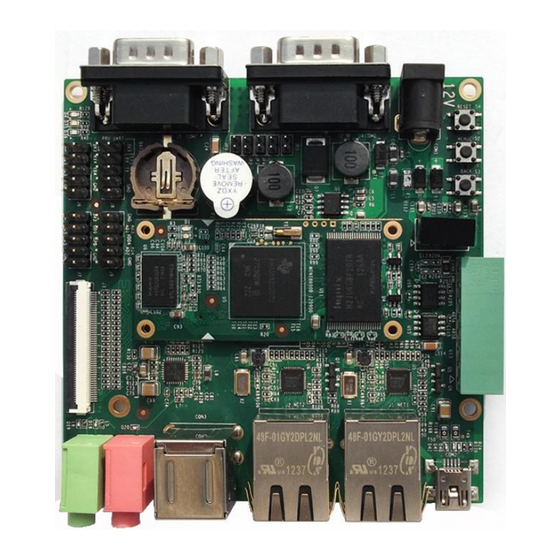
Page 9: Board Interfaces
1.3 Board Interfaces Figure 1: SBC8600B Interfaces Page | 2... -
Page 10: System Block Diagram
1.4 System Block Diagram Figure 2: SBC8600B System Block Diagram Page | 3... -
Page 11: Physical Dimensions
1.5 Physical Dimensions Figure 3: MINI8600B Physical Dimensions Page | 4... - Page 12 Figure 4: SBC8600B Physical Dimensions Page | 5...
-
Page 13: Hardware Features
2 Hardware Features 2.1 Processor 720-MHz ARM Cortex™-A8 32-Bit RISC Microprocessor NEON™ SIMD Coprocessor 32KB/32KB of L1 Instruction/Data Cache with Single-Error Detection (parity) 256KB of L2 Cache with Error Correcting Code (ECC) SGX530 Graphics Engine ... -
Page 14: Operational Parameters
GPMC Signals Note: Some of the pins are multiplexed for UART、IIC、SPI、CAN. Please refer to the CPU datasheet and schematics on the DVD for details. 2.4 Operational Parameters Working Temperature: 0 °C~ 70°C Working Humidity: 20% ~ 90%, Non-Condensing ... -
Page 15: Hardware Details
3 Hardware Details 3.1 Introduction to CPU The AM335x microprocessors, based on the ARM Cortex-A8, are enhanced with image and graphics processing, peripherals, and industrial interface options such as EtherCAT and PROFIBUS. The device has support for high-level operating systems such as Linux, WinCE and Android. The AM335x microprocessor contains these subsystems: ... -
Page 16: General-Purpose Interfaces
Advanced Shader Feature Set in Excess of Microsoft VS3.0, PS3.0 and OGL2.0 Industry Standard API Support of Direct3D Mobile, OGL-ES 1.1 and 2.0, OpenVG 1.0, and OpenMax 3.3 Introduction to Peripherals 3.3.1 NAND Flash H27U4G8F2DTR-BC The H27U4G8F2DTR-BC is a 512M NAND Flash used on SBC8600B. Page | 9... -
Page 17: Ddr H5Tq2G83Cfr-H9C
If you need to know more about the SDRAM, please refer to H5TQ2G83DFR.pdf under Disk-SBC8600B\HW design\datasheet\DDR\. 3.3.3 Ethernet AR8035 AR8035 is a low-power and low-cost Ethernet PHY used on SBC8600B and integrated with a 10/100/1000Mb transceiver. It is a single-port tri-speed Ethernet PHY and supports MAC.TM RGMII interfaces. -
Page 18: Hardware Interfaces
4 Hardware Interfaces 4.1 MINI8600B 4.1.1 CN1 Interface Figure 5: MINI8600B CN1 Interface Signal Function VDDS_RTC Supply voltage for RTC CLK_OUT1 Clock out1 CLK_OUT2 Clock out2 MMC0_DAT0 MMC0 data bus MMC0_DAT1 MMC0 data bus MMC0_DAT2 MMC0 data bus GLOBLE_RESETN SYS_RESET IN/ OUTPUT MMC0_DAT3 MMC0 data bus AM335X_PWRON_RESETN... - Page 19 Signal Function AM355X_PRU_UART0_RX PRU UART0 receive data AM355X_PRU_UART0_RTS PRU UART0 request to send AM355X_PRU_UART0_TX PRU UART0 transmit data AM355X_UART0_RX UART0 receive data AM355X_UART3_RX UART3 receive data AM355X_UART0_TX UART0 transmit data AM355X_UART3_TX UART3 transmit data AM355X_CAN0_RX CAN0 receive data AM355X_I2C0_SDA I2C0 master serial data AM355X_CAN0_TX CAN0 transmit data AM355X_I2C0_SCL...
- Page 20 Signal Function MII1_TXD3 MII1 transmit data MII1_CRS MII1 carrier sense MII1_TXD2 MII1 transmit data MII1_RX_ER MII1 receive data error MII1_TXD1 MII1 transmit data MII1_RX_DV MII1 receive data valid MII1_TXD0 MII1 transmit data MII1_RX_CLK MII1 receive clock MII_MDIO MII MDIO DATA MII1_RXD3 MII1 receive data MII_MDC...
- Page 21 Signal Function USB1_VBUS USB1 bus voltage GPMC_A0 GPMC address GPMC_A7 GPMC address GPMC_A5 GPMC address GPMC_A11 GPMC address GPMC_A4 GPMC address GPMC_A10 GPMC address GPMC_A3 GPMC address GPMC_A9 GPMC address GPMC_A2 GPMC address GPMC_A8 GPMC address GPMC_A6 GPMC address GPMC_A1 GPMC address VDD_3V3 Power...
-
Page 22: Cn2 Interface
4.1.2 CN2 Interface Figure 6: SBC8600B CN2 Interface MODE1 Function MCASP0_AHCLKX MCASP0 transmit master clock MCASP0_ACLKX MCASP0 transmit bit clock MCASP0_FSX MCASP0 transmit frame sync MCASP0_AXR0 MCASP0 serial data(I/O) MCASP0_AHCLKR MCASP0 receiver master clock MMC0_CLK MMC0 clock MCASP0_FSR MCASP0 receive frame sync... - Page 23 MODE1 Function AM355X_ADC4 ADC4 AM355X_ADC5 ADC5 AM355X_ADC6 ADC6 AM355X_ADC7 ADC7 GND_ADC GND ADC LCD_DATA1 LCD data bus LCD_DATA12 LCD data bus LCD_DATA0 LCD data bus LCD_DATA10 LCD data bus LCD_DATA5 LCD data bus LCD_DATA13 LCD data bus LCD_DATA4 LCD data bus LCD_DATA11 LCD data bus LCD_DATA6...
- Page 24 MODE1 Function GPMC_AD11 GPMC address & data LCD_DATA3 LCD data bus GPMC_AD15 GPMC address & data LCD_DATA2 LCD data bus GPMC_AD14 GPMC address & data LCD_DATA7 LCD data bus GPMC_WAIT0 GPMC wait0 LCD_HSYNC LCD horizontal sync GPMC_BEN1 GPMC byte enable 1 LCD_EN LCD AC bias enable chip select GPMC_WPN...
- Page 25 MODE1 Function GPMC_CSN1 GPMC chip select1 GPMC address valid/address GPMC_ADVN_ALE latch enable GPMC_AD5 GPMC address & data GPMC byte enable 0/Command GPMC_BEN0_CLE latch enable GPMC_AD4 GPMC address & data GPMC_OEN_REN GPMC output /read enable GPMC_AD1 GPMC address & data GPMC_AD2 GPMC address &...
-
Page 26: Extension Board
4.2 Extension Board Figure 7: Extension Board Interfaces The interface is on the bottom of the board The interface is on the top of the board 4.2.1 Power Jack CON1 Signal Description +12V Power supply (+12V) Page | 19... -
Page 27: Tft_Lcd Interface
4.2.2 TFT_LCD Interface Signal Description LCD Pixel data bit 0 LCD Pixel data bit 1 LCD Pixel data bit 2 LCD Pixel data bit 3 LCD Pixel data bit 4 GND1 LCD Pixel data bit 5 LCD Pixel data bit 6 LCD Pixel data bit 7 LCD Pixel data bit 8 LCD Pixel data bit 9... - Page 28 Signal Description LCD Pixel data bit 13 LCD Pixel data bit 14 LCD Pixel data bit 15 GND3 AC bias control (STN) or pixel data enable (TFT) HSYNC LCD Horizontal Synchronization VSYNC LCD Vertical Synchronization LCD Pixel Clock GND4 X+ Position Input X- Position Input Y+ Position Input Y- Position Input...
-
Page 29: Audio Output Interface
Signal Description VDD4 RESET Reset PWREN Backlight enable Note: Please do NOT disconnect the LCD flat cable while the board is powered on. 4.2.3 Audio Output Interface HEADPHONE1 Signal Description Right Right output Left Left output Page | 22... -
Page 30: Audio Input Interface
4.2.4 Audio Input Interface MIC1 Signal Description MIC IN Input MIC IN Input 4.2.5 USB HOST Interface CON3 Signal Description VBUSA USB Data- USB Data+ GNDA 4.2.6 USB OTG Interface CON2 Signal Description USB Data- USB Data+ USB ID Page | 23... -
Page 31: Tf Card Interface
4.2.7 TF Card Interface Signal Description DAT2 Card data 2 CD/DAT3 Card data 3 Command Signal CLOCK Clock DAT0 Card data 0 DAT1 Card data 1 Card detect 4.2.8 LAN Interface J1,J2 Signal Description TD1+ Transmit Data1+ TD1- Transmit Data1- TD2+ Transmit Data2+ TD2-... -
Page 32: Serial Interface
J1,J2 Signal Description GRLC LINK active LED YELC 100M linked LED YELA +2.5V 4.2.9 Serial Interface J4(UART0), J5(UART2) Signal Description Receive data Transmit data Request To Send Clear To Send 4.2.10 CAN&RS485 Interface Signal Description +12V +12V GND2 Isolated GND 485B1 485B 485A1... -
Page 33: Adc Interface
Signal Description CANL1 CANL CANH CANH 4.2.11 ADC Interface Signal Description ADC_CH1 ADC1 ADC_CH3 ADC3 VDDA_ADC Power VDDA_ADC Power ADC_CH2 ADC2 ADC_CH4 ADC4 4.2.12 SPI Interface Signal Description +3.3V 3.3V +3.3V 3.3V SPI0_D1 SPI0 data1 SPI0_CLK SPI0 clock SPI0_CS0 SPI enable0 SPI0_D0 SPI data0 Page | 26... -
Page 34: Extension Interface
Signal Description 4.2.13 Extension Interface Signal Description VIO_3V3 +3.3V VIO_3V3 +3.3V UART3_TX_3V3 UART3 Transit data 3.3V level UART4_TX_3V3 UART4 Transit data 3.3V level UART3_RX_3V3 UART3 receive data 3.3V level UART4_RX_3V3 UART4 receive data 3.3V level Signal Description VIO_3V3 +3.3V VIO_3V3 +3.3V UART5_TX_3V3 UART5 Transit data 3.3V level... -
Page 35: Buttons
UART5_RX_3V3 UART5 receive data 3.3V level GPIO2_0 GPIO 4.2.14 Buttons S1-3 Signal Description MENU System menu key BACK System back key Reset System Reset key 4.2.15 LEDs LEDs Definition Description Power Indicator User Custom LED User Custom LED Page | 28... -
Page 36: Linux Operating System
5 Linux Operating System 5.1 Introduction This chapter will introduce the Linux software system of SBC8600B through the following topics: Introducing the software resources provided along with SBC8600B Introducing the software features. Introducing the creation of a development environment, system development, driver principles and development. -
Page 37: Software Features
Features and functions of each part of the system are listed below: 1. spl is a first level bootstrap program. After the system starts up, the ROM inside the CPU will copy spl to internal RAM and perform its routine work. Its main function is to initialize the CPU, copy u-boot into the memory and let u-boot lead the booting process;... -
Page 38: System Development
5.4 System Development 5.4.1 Establishment of development environment Before developing software for the SBC8600B, users have to establish a Linux cross development environment on the PC. This section will use the Ubuntu operating system as an example to introduce how to establish a cross development environment. -
Page 39: Addition Of Environment Variables
mkdir $HOME/tools cd /media/cdrom/linux/tools tar arm-2009q1-203-arm-none-linux-gnueabi-i686-pc-linux-g nu.tar.bz2 -C $HOME/tools tar xvf arm-eabi-4.4.0.tar.bz2 -C $HOME/tools Some of the other development tools used for source code compilation are saved under the same directory; the user can execute the following commands to copy them to local folder: ... -
Page 40: Establishment Of Android Development Environment
6 Establishment of Android Development Environment Apart from the cross compilation tools and environment variables, there are a few additional software packages which need to be installed and several configurations that need to be set in the Ubuntu system before any Android system source code can be compiled. -
Page 41: Compilation Of Boot Code
6.1.2 Compilation of boot code SBC8600B can boot up from TF card or NAND Flash, with the former as the first boot-up device and the latter as the secondary. We will introduce the generation of boot code image files for both the boot-up devices. -
Page 42: Android System Compilation
Please visit: http://www.elinux.org/DevKit8600_FAQ For details of how to generate a RAMdisk file. 2. UBI file cd $HOME/work sudo $HOME/tools/mkfs.ubifs -r rootfs -m 2048 -e 126976 -c 812 -o ubifs.img sudo $HOME/tools/ubinize -o ubi.img -m 2048 -p 128KiB -s 512 -O 2048 $HOME/tools/ubinize.cfg After above operations are executed, a ubi.img file will be generated under the current directory. -
Page 43: System Customization
ubi.img can be found under temp/. Note: Before the compilation of Android file system, the Android kernel source code Linux-3.1.0-android needs to be compiled first, or errors might occur during the process. 6.3 System Customization As the Linux kernel has many kernel configuration options, users can add or remove drivers and some kernel features in the default configuration to meet specific requirements. -
Page 44: Compilation
Device Drivers USB support USB Gadget Support USB Gadget Drivers Type <M> for “File-backed Storage Gadget”, and select Save when you exit, and compile the kernel again. 6.3.2 Compilation Save configuration, execute the following commands to recompile kernel: ... -
Page 45: Introduction To Drivers
6.4 Introduction to Drivers 6.4.1 NAND The Solid-state memory used in embedded systems is mainly flash; this system uses NAND Flash. NAND Flash is used as a block device, on which the file system is arranged; interaction between the user and NAND Flash is mainly administered by a specific file system. -
Page 46: Sd/Mmc
Linux-3.2.0-psp04.06.00.08.sdk/drivers/mtd/nand/omap2.c 6.4.2 SD/MMC The SD/MMC card drivers under Linux mainly include four parts: SD/MMC core, mmc_block, mmc_queue and the SD/MMC driver: 1. SD/MMC core handles core codes unrelated to structure in the SD/MMC card operation. 2. mmc_block controls driver structure when SD/MMC card is used as a block device. -
Page 47: Lcdc
Drivers and relevant documents: Linux-3.2.0-psp04.06.00.08.sdk/drivers/mmc/ Linux-3.2.0-psp04.06.00.08.sdk/drivers/mmc/host/omap_hsmmc.c 6.4.3 LCDC The LCD controller (LCDC) of AM335x is the latest version integrated in OMAP-L138 SoC which has differences as follows comparing with OMAP-L138. Interrupt configuration and status registers are different ... -
Page 48: Audio In/Out
6.4.4 Audio in/out ASoC basically splits an embedded audio system into three components: Codec driver: The codec driver is platform independent and contains audio controls, audio interface capabilities, codec dapm definition and codec IO functions. Platform driver: The platform driver contains the audio dma engine and audio interface drivers (e.g. -
Page 49: Driver Development
6.5 Driver Development 6.5.1 Driver for the gpio_keys 1. Device definition Linux-3.2.0-psp04.06.00.08.sdk/arch/arm/mach-omap2/board-am335xev Setup GPIO 0.2 as a “menu” key, return value as “KEY_F1”, triggered on low level; set GPIO 2.1 as a ”back”key, return value as ”KEY_ESC”, triggered on low level, the structure template is shown below. static struct gpio_keys_button gpio_key_buttons[] = { .code = KEY_F1,... - Page 50 2. GPIO pinmux Configuration Define the GPIO0.20 and GPIO2.1 as MODE7 (GPIO mode) and AM33XX_PIN_INPUT (configuration input). Linux-3.2.0-psp04.06.00.08.sdk/arch/arm/mach-omap2/board-am335xev static struct pinmux_config gpio_keys_pin_mux[] = { {"xdma_event_intr1.gpio0_20",OMAP_MUX_MODE7 | AM33XX_PIN_INPUT}, {"gpmc_clk.gpio2_1",OMAP_MUX_MODE7|AM33XX_PIN_INPUT}, {NULL, 0}, 3. Driver Design Linux-3.2.0-psp04.06.00.08.sdk/drivers/input/keyboard/gpio_keys.c Call platform_driver_register to register gpio_keys driver static struct platform_driver gpio_keys_device_driver = { .probe = gpio_keys_probe,...
- Page 51 MODULE_DESCRIPTION("Keyboard driver for GPIOs"); MODULE_ALIAS("platform:gpio-keys"); Call input_register_device to register input driver static int __devinit gpio_keys_probe(struct platform_device *pdev) … input = input_allocate_device(); … for (i = 0; i < pdata->nbuttons; i++) { struct gpio_keys_button *button = &pdata->buttons[i]; struct gpio_button_data *bdata = &ddata->data[i]; unsigned int type = button->type ?: EV_KEY;...
- Page 52 struct gpio_keys_button *button) const char *desc = button->desc ? button->desc : "gpio_keys"; struct device *dev = &pdev->dev; unsigned long irqflags; int irq, error; setup_timer(&bdata->timer, gpio_keys_timer, (unsigned long)bdata); INIT_WORK(&bdata->work, gpio_keys_work_func); error = gpio_request(button->gpio, desc); if (error < 0) { dev_err(dev, "failed to request GPIO %d, error %d\n", button->gpio, error);...
- Page 53 if (!button->can_disable) irqflags |= IRQF_SHARED; error = request_threaded_irq(irq, NULL, gpio_keys_isr, irqflags, desc, bdata); if (error < 0) { dev_err(dev, "Unable to claim irq %d; error %d\n", irq, error); goto fail3; return 0; fail3: gpio_free(button->gpio); fail2: return error; Interrupt processing When button is pressed, an interrupt is generated and key value is displayed.
-
Page 54: Driver For The Gpio_Leds
input_event(input, type, button->code, !!state); input_sync(input); 6.5.2 Driver for the gpio_leds 1. Device Definition Linux-3.2.0-psp04.06.00.08.sdk/arch/arm/mach-omap2/board-am335xev Configure GPIO 1.30 as ”sys_led” (system indicator)and GPIO 1.31 as “user_led”, both activated by a high level signal. static struct gpio_led gpio_leds[] = { .name = "sys_led", .default_trigger = "heartbeat", .gpio... - Page 55 Configure GPIO1.30 and GPIO1.31 as MODE7 (GPIO mode) and AM33XX_PIN_OUTPUT (configuration output) static struct pinmux_config gpio_led_pin_mux[] = { {"gpmc_csn1.gpio1_30", OMAP_MUX_MODE7 | AM33XX_PIN_OUTPUT}, {"gpmc_csn2.gpio1_31", OMAP_MUX_MODE7 | AM33XX_PIN_OUTPUT}, {NULL, 0}, Driver Design Linux-3.2.0-psp04.06.00.08.sdk/drivers/leds/leds-gpio.c Call platform_driver_register to register gpio_leds driver static struct platform_driver gpio_led_driver = { .probe = gpio_led_probe, .remove...
- Page 56 static int __devinit gpio_led_probe(struct platform_device *pdev) … if (pdata && pdata->num_leds) { priv = kzalloc(sizeof_gpio_leds_priv(pdata->num_leds), GFP_KERNEL); if (!priv) return -ENOMEM; priv->num_leds = pdata->num_leds; for (i = 0; i < priv->num_leds; i++) { ret = create_gpio_led(&pdata->leds[i], &priv->leds[i], &pdev->dev, pdata->gpio_blink_set); if (ret < 0) { /* On failure: unwind the led creations */ for (i = i - 1;...
-
Page 57: Updating The System
6.6.1 Updating the TF card system image 1. Formatting the MMC/SD card The HP USB Disk Storage Format Tool is recommended: The software can be downloaded from: http://www.embest-tech.com/resource/download/HP-USB-Disk-St orage-Format-Tool.rar Insert the TF card into the card reader of the PC. ... - Page 58 Figure 9: HP USB Disk Storage Format Tool Settings Select “FAT32” from the file system drop down box. Click “Start”. When formatting is completed, click “OK”. Note: HP USB Disk Storage Format Tool will erase the partitions of TF card. ...
- Page 59 Booting from MMC... OMAP SD/MMC: 0 reading u-boot.img reading u-boot.img U-Boot 2011.09-svn55 (Dec 04 2012 - 09:29:02) I2C: ready DRAM: 512 MiB WARNING: Caches not enabled Did not find a recognized configuration, assuming General purpose EVM in Profile 0 with Daughter board NAND: HW ECC Hamming Code selected 512 MiB MMC:...
- Page 60 G++ Lite 2009q1-203) ) #17 Fri Dec 7 10:04:07 CST 2012 ……… ……… RAMDISK: gzip image found at block 0 VFS: Mounted root (ext2 filesystem) on device 1:0. Freeing init memory: 260K INIT: version 2.86 booting Starting udevudevd (741): /proc/741/oom_adj is deprecated, please use /proc/741/oom_score_adj instead.
-
Page 61: Updating Nand Flash
The above information indicates a successful boot-up of Linux from the TF card. Note: The default display is a 4.3” LCD. If you are working with the LCDs of other size, please enter u-boot when the board is booting up to configure the display mode, and then type boot to continue boot-up process. - Page 62 Note: You may short the jumper JP5 on the board to allow SBC8600B boot up from TF card and enter uboot to write the image in NAND Flash, and then disconnect JP5 to allow system boot up from NAND Flash.
-
Page 63: Instructions
NAND write: device 0 offset 0x80000, size 0x39590 234896 bytes written: OK reading uImage 3224184 bytes read HW ECC BCH8 Selected NAND write: device 0 offset 0x280000, size 0x313278 3224184 bytes written: OK reading ubi.img 14811136 bytes read SW ECC selected NAND write: device 0 offset 0x780000, size 0xe20000 Skip bad block 0x00ce0000 14811136 bytes written: OK... -
Page 64: Using A 4.3" Lcd Display
U-Boot SPL 2011.09-svn55 (Nov 20 2012 - 10:37:42) I2C: ready DRAM: 512 MiB WARNING: Caches not enabled Did not find a recognized configuration, assuming General purpose EVM in Profile 0 with Daughter board NAND: HW ECC Hamming Code selected 512 MiB MMC: OMAP SD/MMC: 0 *** Warning - bad CRC, using default environment... -
Page 65: Using A 7" Lcd Display
6.7.3 Using a 7” LCD Display Modify the parameter by executing the command as follows in the U-boot command mode. SBC8600# setenv dispmode 7inch_LCD SBC8600# saveenv 6.7.4 Using a VGA Display Modify the parameter by executing the command as follows in the U-boot command mode. - Page 66 root@SBC8600:~# evtest /dev/input/event1 Input driver verevdev: (EVIOCGBIT): Suspicious buffer size 511 Input device ID: bus 0x19 vendor 0x1 product 0x1 version 0x100 Input device name: "gpio-keys" Supported events: Event type 0 (Sync) Event type 1 (Key) Event code 1 (Esc) Event code 59 (F1) Testing ...
-
Page 67: Touch Screen Testing
6.8.3 Touch Screen Testing This test requires the Linux system to boot up from NAND Flash. 1. Execute the following instruction to test touch-screen root@SBC8600: # ts_calibrate The LCD display will guide you to click the "+" icon 5 times to complete the calibration. -
Page 68: Rtc Testing
/sys/class/backlight/pwm-backlight/brightness The screen is now turned to maximum brightness. 6.8.5 RTC Testing The development board contains a hardware clock to save and synchronize the system time. A test can be accomplished with the following steps: 1. Set the system time as Mar 22 20:00:00 2012 root@SBC8600: # date 032220002012 Thu Mar 22 20:00:00 UTC 2012 Write the system clock into RTC... -
Page 69: Tf Card Testing
Note: You may find the RTC stops running in the scenario where the board is powered off and then powered on again. This is caused by a bug in the CPU. Please refer to the errata provided by TI. ... -
Page 70: Usb Device Testing
Note: The system can mount the TF card automatically when you insert it on the board. However, we recommend mounting it manually because automatic mounting may lead to a slow writing speed. 6.8.7 USB DEVICE Testing USB DEVICE testing is accomplished by using a cable to connect the miniUSB interface of the development board to the USB interface on a PC;... - Page 71 4. Right-click virtual network adapter on the PC and select “Properties”, and then double-click the “Internet Protocol (TCP/IP)” to configure the IP address of the virtual network adapter: Figure 10: IP Configuration Use the ping command in the HyperTerminal to test whether the settings of the development board are correct: root@SBC8600:~# ping 192.168.1.15 PING 192.168.1.15 (192.168.1.15): 56 data bytes...
-
Page 72: Usb Host Testing
6.8.8 USB HOST Testing 1. After inserting the USB flash disk on the board, the system will mount the disk under the directory /media automatically; root@SBC8600:~# df -h Filesystem Size Used Available Use% Mounted on rootfs 31.0M 19.7M 11.3M 64% / /dev/root 31.0M 19.7M... -
Page 73: Audio Testing
tmpfs 250.6M 3.0M 247.6M 1% /media/ram /dev/sda1 99.2M 3.3M 95.9M 3% /media/card 6.8.9 AUDIO Testing The board has audio input and output interfaces. Users can enter the following instructions to test alsa-utils audio player and recorder in the file system: 1. - Page 74 root@SBC8600:~# aplay -t wav -c 2 -r 44100 -f S16_LE -v k Playing WAVE 'k' : Signed 16 bit Little Endian, Rate 44100 Hz, Mono Plug PCM: Route conversion PCM (sformat=S16_LE) Transformation table: 0 <- 0 1 <- 0 Its setup is: stream : PLAYBACK access...
-
Page 75: Network Testing
6.8.10 Network Testing 1. There are two Ethernet interfaces, NET1 (J1) and NET2 (J2), associated with two device nodes, eth0 and eth1. Please use two network cables to connect the interfaces to a network and ensure that the IP addresses of the interfaces are set in different network subnets. -
Page 76: Can Testing
64 bytes from 192.168.168.121: seq=1 ttl=64 time=0.319 ms The above information indicates a successful network test. 6.8.11 CAN Testing SBC8600B can work as a CAN device. Please connect the CAN interfaces on your SBC8600B and another CAN device according to the schematics and the figure shown below:... - Page 77 2. Transmit and receive data on the two devices respectively by typing the following instructions. root@SBC8600:~# cansend can0 -i 0x10 0x11 0x22 0x33 0x44 0x55 0x66 0x77 0x88 Note: The instruction sends data only once. Type it again to send another date package.
-
Page 78: Rs485 Testing
(not simultaneously). Copy the file uart_test under linux\example\uart_test onto the TF card, and then insert the card into the SBC8600B and execute the following instructions: root@SBC8600:~# cd /media/mmcblk0p1/ root@SBC8600:/media/mmcblk0p1# ./uart_test -d /dev/ttyO1 -b 115200... -
Page 79: Serial Interface Testing
/dev/ttyO2 RECV 10 total /dev/ttyO2 RECV: 1234567890 The same testing method can be applied on serial interfaces 3, 4 and 5 of J6 and J7 on the SBC8600B 6.8.14 Buzzer Testing 1. Enable the buzzer; root@SBC8600:~# echo 1 > /sys/class/misc/buzzer_ctl/state 2. -
Page 80: Cdma8000-U Module
http://www.timll.com/chinese/uploadFile/cdma8000.rar 6.9 Demo 6.9.1 Android System Demonstration SBC8600B provides an Android system demonstration, please follow the steps listed below: 1. Copy all files under the directory \linux\demo\Android\image of the DVD-ROM to a TF card; 2. Insert the TF card on the board and short jumper JP5, and then power on the board. - Page 81 Skipping bad block at 0x03620000 Erasing at 0x1ffe0000 -- 100% complete. reading MLO 36079 bytes read HW ECC BCH8 Selected NAND write: device 0 offset 0x0, size 0x8cef 36079 bytes written: OK reading flash-uboot.img 234620 bytes read HW ECC BCH8 Selected NAND write: device 0 offset 0x80000, size 0x3947c 234620 bytes written: OK reading uImage...
-
Page 82: Tisdk System Demonstration
6.9.2 TISDK System Demonstration 1. Format a TF card into two partitions by following the steps described in 7Appendix 3:Making a Linux Boot Disk; 2. Insert the DVD-ROM and TF card into the PC, and then execute the following instructions: cp /media/cdrom/linux/demo/tisdk/image/MLO /media/LABEL1 /media/cdrom/linux/demo/tisdk/image/u-boot.img /media/LABEL1... - Page 83 CCCCCCCC U-Boot SPL 2011.09-svn55 (Dec 04 2012 - 09:33:23) Texas Instruments Revision detection unimplemented Booting from MMC... OMAP SD/MMC: 0 reading u-boot.img reading u-boot.img U-Boot 2011.09-svn55 (Dec 04 2012 - 09:33:23) I2C: ready DRAM: 512 MiB WARNING: Caches not enabled Did not find a recognized configuration, assuming General purpose EVM in Profile 0 with Daughter board NAND: HW ECC Hamming Code selected...
-
Page 84: Application Development
The TISDK file system features some applications running on QT which allow users find and run example programs easily through a friendly graphic interface. Note: The system image supports 4.3” display by default. If you are working with a display of another size, you need to modify the parameters in UBOOT. - Page 85 return -1; for(;;){ i++; dat1 = i&0x1 ? '1':'0'; dat2 = (i&0x2)>>1 ? '1':'0'; write(f_led1, &dat1, sizeof(dat1)); write(f_led2, &dat2, sizeof(dat2)); usleep(300000); Cross compiling arm-none-linux-gnueabi-gcc led_acc.c -o led_acc 3. Downloading and running Download the code to the development board system through a TF card, a USB flash disk or the network connection and enter the directory where the led_acc file is saved, and then execute the following instructions to run led_acc in the background.
-
Page 86: Wince Operating System
7 WinCE Operating System 7.1 Introduction This section mainly introduces the SBC8600B system and application development of Windows Embedded CE 6.0 R3, as well as software resources on the disc, software features, establishment of a development environment, and how to build sysgen and the BSP (board support package) and so on. -
Page 87: Software Features
Ebootnd.nb0 Second bootloader for NAND flash boot Nk.bin WinCE runtime image 7.3 Software Features Resources Contents of BSP: Catalogue Item Source code / binary X-Loader NAND Source (First boot loader) Source EBOOT NAND Source (Second boot source loader) Boot parameter Source KILT(EMAC) Source... -
Page 88: System Development
TOUCH driver Source SD/MMC/SDIO driver Source EMAC driver Source USB OTG driver Source GPIO keyboard driver Source DMA driver Source Backlight driver Source Battery driver Source RPU driver Source powerVR DDK & SDK Binary & Source 7.4 System Development 7.4.1 Installation of Integrated Development Environment Please install all the items below to windows XP/Vista in the order listed: 1. -
Page 89: Sysgen & Build Bsp
2. Extract [CD\WINCE700\BSP\COMMON_TI_V1.rar] to [C:\WINCE700\PLATFORM\COMMON\SRC\SOC]. 3. Extract [CD\WINCE700\BSP\3rdParty.rar] to [C:\WINCE700]. 4. Extract [CD\WINCE700\BSP\powerVR.rar] to [C:\WINCE700\public]. 5. Extract [CD\WINCE700\project\SBC8600.rar] to the [C:\WINCE700\OSDesigns] directory. Note: The default installation path of the Windows Embedded Compact 7 in this context is [C:\WINCE700]. 7.4.3 Sysgen & Build BSP Below are the steps given for building Sysgen and the BSP: Open the existing project file SBC8600.sln located in 1)... -
Page 90: Driver Introduction
7.4.4 Driver Introduction Source code path of all drivers in BSP: NLED driver BSP\SBC8600\SRC\DRIVERS\NLED BSP\SBC8600\SRC\DRIVERS\GPIO GPIO BSP\COMMON_TI_V1\COMMON_TI_AMXX\GPIO BSP\COMMON_TI_V1\COMMON_TI_AMXX\OAL\OALI2C BSP\COMMON_TI_V1\COMMON_TI_AMXX\SPI BSP\SBC8600\SRC\DRIVERS\MCSPI MCASP driver BSP\COMMON_TI_V1\COMMON_TI_AMXX\MCASP BSP\COMMON_TI_V1\COMMON_TI_AMXX\SERIAL Serial port driver BSP\SBC8600\SRC\DRIVERS\UART Audio driver BSP\SBC8600\SRC\DRIVERS\WAVEDEV2 BSP\SBC8600\SRC\DRIVERS\BLOCK NAND driver BSP\COMMON_TI_V1\COMMON_TI_AMXX\BLOCK BSP\COMMON_TI_V1\COMMON_TI_AMXX\DSS_Netra Display driver BSP\SBC8600\SRC\DRIVERS\DISPLAY TOUCH driver BSP\SBC8600\SRC\DRIVERS\TOUCH BSP\SBC8600\SRC\DRIVERS\SDHC SD/MMC/SDIO driver... -
Page 91: Updating The System Image
Content(C) Windows Embedded Compact 7->Device Driver. 7.5 Updating the System Image The SBC8600B supports boot-up from a TF card and NAND; this section will respectively introduce the two different system update methods. 7.5.1 Update TF Card Image 1. Format TF Card HP USB Disk Storage Format Tool 2.0.6 is recommended:... - Page 92 Open the HP USB Disk Storage Format Tool, the following window will be displayed. Figure 13: HP USB Disk Storage Formatting Tool Settings Select “FAT32” from the file system drop down box. Click “Start”. When formatting is complete then click “OK”. Note: ...
- Page 93 Insert a TF card and reboot the system. And then, the system will boot from the TF card. Press the space button and enter EBOOT menu. To select boot device and LCD module display output, follow these steps: Enter EBOOT menu CCCCCCCC Texas Instruments Windows CE SD X-Loader33X Built Jul 27 2012 at 11:25:59...
- Page 94 e0311800 56e4 -> 0 18 31 e0 e4 56 e0311800 57e4 -> 0 18 31 e0 e4 57 Hit space to enter configuration menu [56] 5...(Press the space key to enter EBOOT menu) Type [2]->[2] select boot from TF card ---------------------------------------------------------------------------- ---- Main Menu...
- Page 95 [1] Show Current Settings [2] Select Boot Device [3] Select KITL (Debug) Device [4] Network Settings [5] SDCard Settings [6] Set Device ID [7] Save Settings [8] Flash Management [9] Enable/Disable OAL Retail Messages [a] Select Display Resolution [b] Select OPP Mode [0] Exit and Continue Selection: a ----------------------------------------------------------------------------...
- Page 96 [a] Select Display Resolution [b] Select OPP Mode [0] Exit and Continue Selection: 0 mode = 3 LcdPdd_LCD_GetMode:3 mode = 3 LcdPdd_LCD_Initialize:3 OEMPreDownload: Filename nk.bin Init HW: controller RST SDCARD: requested speed 1000000, actual speed 1000000 SDCARD: requested speed 25000000, actual speed 19200000 BL_IMAGE_TYPE_BIN +OEMMultiBinNotify(0x8feb24d8 ->...
-
Page 97: Update Nand Flash Image
7.5.2 Update NAND Flash image Format TF Card Please refer to p84. Copy Runtime Image Copy MLO, EBOOTND.nb0, NK.bin, XLDRNAND.nb0 and EBOOTSD.nb0 image files located in CD\WINCE700\image to the TF card. Flashing Image File Insert the TF card and reboot the system. The system will then boot from the TF card. -
Page 98: Application Development
This chapter introduces how to develop Windows Embedded Compact 7 application programs in SBC8600B. 7.7.1 Application Program Interfaces and Examples The API used for development of SBC8600B application programs employs the Microsoft Windows Embedded Compact 7 standard application program interface definition, SBC8600B only expands the interface definitions of... - Page 99 IOCTL_GPIO_GETMODE Read the working mode of GPIO pin IOCTL_GPIO_GETIRQ Read the corresponding IRQ of GPIO pin An example is shown below: 1. Open the GPIO device HANDLE hFile CreateFile ("GIO1:"), (GENERIC_READ|GENERIC_WRITE), (FILE_SHARE_READ|FILE_SHARE_WRITE), 0, OPEN_EXISTING, 0, 0); 2. Set the working mode of the GPIO DWORD id = 48, mode = GPIO_DIR_OUTPUT;...
- Page 100 DeviceIoControl (hFile, IOCTL_GPIO_SETBIT, &id, sizeof (DWORD), NULL, 0, NULL, NULL); Output low level: DeviceIoControl (hFile, IOCTL_GPIO_CLRBIT, &id, sizeof (DWORD), NULL, 0, NULL, NULL); Read the pin state DeviceIoControl (hFile, IOCTL_GPIO_GETBIT, &id, sizeof (DWORD), &pinState, sizeof (DWORD), NULL, NULL); "id" is the GPIO pin number, "pinSate" returns to pin state Other optional operations Read the corresponding IRQ number of a GPIO pin DWORD id = 0, irq = 0;...
-
Page 101: Appendix 1: Installing An Ubuntu Linux System
Appendix 1: Installing an Ubuntu Linux System An appropriate development environment is required for software development. The CD included with the product contains a development environment which needs to be installed under a Linux environment. If you are working on a PC running Windows, you have to create a Linux system first, and then you can install the environment. - Page 102 2. Click Next to create a new virtual machine. 3. Enter a name for the new virtual machine and select the operating system type as shown below: Enter a name in the Name field, e.g. Ubuntu, and select Linux in the Operating System drop-down menu, and then click Next.
- Page 103 Note: If your PC has 1GB of RAM or lower, keep the default setting; If your PC has more than 1GB of RAM, you can allocate up to 1/4 to the virtual machine, for example, 512MB out of 2GB memory could be allocated to virtual machine.
- Page 104 7. Select Fixed-size storage in the following window and click Next 8. Define where the hard disk data is stored and the default space of the virtual disk (8GB at least), and then click Next 9. Click Finish in the following window Page | 97...
- Page 105 10. Your PC will then create a new virtual disk 11. A window with summary of the newly created virtual machine will be shown as below when the creation process is done. Please click Finish to complete the whole process. Page | 98...
-
Page 106: Installing The Ubuntu Linux System
1.2 Installing the Ubuntu Linux System After VirtualBox is installed, we can install the Ubuntu Linux system. Visit: http://www.Ubuntu.com/download/Ubuntu/download to download the ISO image file of Ubuntu and then follow the steps below: 1. Start VirtualBox from the Start menu and click Settings on the VirtualBox window. - Page 107 3. Select the ISO file you downloaded and click OK as shown below 4. Click Start on the VirtualBox window, the Ubuntu installation program will start as shown below: Page | 100...
- Page 108 5. Some prompt windows will pop up during the initiation process. You need only click OK all the way to the end of the process. 6. Click Install Ubuntu to start installation when the following window appears 7. Click Forward to continue the process Page | 101...
- Page 109 8. Select Erase disk and install Ubuntu and click Forward Note: Selecting this option will only affect the virtual hard drive you created earlier and will not lead to any content loss on your physical hard drive. 9. Click Install Now in the following window to start the installation: Page | 102...
- Page 110 10. Some simple questions need to be answered during the installation process. Please enter appropriate information and click Forward. The following window is the last question that will appear during the process: 11. After all the required information is properly entered in to the fields, select Log in automatically and click Forward.
- Page 111 Note: The Normally the ISO file shown below will be ejected automatically by VirtualBox after restarting Ubuntu. If it is not, you can eject the ISO file manually in the Settings window of VirtualBox. The following window shows the settings window after the ISO file is ejected. 13.
-
Page 112: Appendix 2: Driver Installation Of Linux Usb Ethernet/Rndis Gadget
Appendix 2: Driver Installation Of Linux USB Ethernet/RNDIS Gadget 1. If you don’t install drivers for the Linux USB Ethernet/RNDIS Gadget, the PC will find the new hardware and give you a hint on the screen, please select “From list or designated location”, then click “Next” 2. - Page 113 3. When the following appears, select “Continue” 4. Please wait until the installation is completed Page | 106...
- Page 114 Page | 107...
-
Page 115: Appendix 3: Making A Linux Boot Disk
Appendix 3: Making a Linux Boot Disk The following content will show you how to create a dual-partition flash disk for booting up a Linux system from the first partition, while saving the root filesystem in the second one; 1. Insert a TF card into a TF card reader and then connect the reader to your PC;... - Page 116 Note: If TF card has two or more partitions, there would be multiple paths such as /dev/sdc1, /dev/sdc2 and /dev/sdc3 corresponding to the partitions. 3. Execute the following instruction to unmount the device; $ umount /media/disk 4. Execute an fdisk instruction; $ sudo fdisk /dev/sdc Please make sure you type the device path for the whole device, not one of the partitions such as /dev/sdc1 or /dev/sdc2;...
- Page 117 Command (m for help): [ x ] (type x to enter expert mode) Expert Command (m for help): [ h ] (type h to set heads) Number of heads (1-256, default xxx): [ 255 ] (set heads to 255) Expert Command (m for help): [ s ] (type s to set sectors) Number of sectors (1-63, default xxx): [ 63 ] (set sector to 8.
- Page 118 Selected partition 1 Hex code (type L to list codes): [ c ] (type c to set partition type) Changed system type of partition 1 to c (W95 FAT32 (LBA)) 11. Type a and 1 to set the TF card to bootable mode; Command (m for help): [ a ] Partition number (1-4): [ 1 ] 12.
- Page 119 Command (m for help): [ w ] The partition table has been altered! Calling ioctl() to re-read partition table. WARNING: Re-reading the partition table failed with error 16: Device or resource busy. The kernel still uses the old table. The new table will be used at the next reboot. WARNING: If you have created or modified any DOS 6.x partitions, please see the fdisk manual page for additional information.
-
Page 120: Appendix 4: Tftp Server Setup
Appendix 4: TFTP Server Setup 1. Install client $>sudo apt-get install tftp-hpa $>sudo apt-get install tftpd-hpa 2. Install inet $>sudo apt-get install xinetd $>sudo apt-get install netkit-inetd 3. Configure the server First, create tftpboot under root directory, and set the properties as “a random user can write and read”... - Page 121 wait = yes user = root server = /usr/sbin/in.tftpd server_args = -s /tftpboot -c per_source = 11 = 100 2 4. Reboot the server: $>sudo /etc/init.d/xinetd restart $>sudo in.tftpd -l /tftpboot 5. Test the server Conduct a test; create a file under folder /tftpboot $>touch abc Enter into another folder $>tftp 192.168.1.15 (192.168.1.15was the server IP)
-
Page 122: Appendix 5: Esd Precautions & Handling Procedures
Appendix 5: ESD Precautions & Handling Procedures Please note that the board comes without any case/box and all components are exposed. Therefore, extra attention must be paid to ESD (electrostatic discharge) precautions. To effectively prevent electrostatic damage, please follow the steps below: ... -
Page 123: Appendix 6: Technical Support & Warranty
Appendix 6: Technical support & Warranty Embest Technology Co., Ltd. established in March of 2000, is a global provider of embedded hardware and software. Embest aims to help customers reduce time to market with improved quality by providing the most effective total solutions for the embedded industry. In the rapidly... -
Page 124: Maintenance Service Clause
Products malfunction due to disassembly or alteration of components by customers, or repair by persons or organizations unauthorized by Embest Technology, or alteration from factory specifications, or configured or expanded with components that are not provided or recognized by Embest Technology;... -
Page 125: Basic Guidelines For Protection And Maintenance Of Lcds
3. Do not clean the surface of the screen with unsuitable chemicals Note: Embest do not supply a maintenance service for LCDs. We suggest the customer immediately checks the LCD once in receipt of the goods. In the event that the LCD does not run or shows no display, the customer should inform Embest within 7 business days of delivery. -
Page 126: Value Added Services
6.4 Value Added Services We will provide following value added services: Driver development based on Embest embedded platforms for devices such as: serial ports, USB interface devices, and LCD screens. Control system transplantation, BSP driver development, API software development.
Need help?
Do you have a question about the SBC8600B and is the answer not in the manual?
Questions and answers