Nibe ACS 45 Installer Manual
Passive/active cooling (4 pipe)
Hide thumbs
Also See for ACS 45:
- Installer manual (92 pages) ,
- Installer manual (60 pages) ,
- Installer manual (32 pages)

Related Manuals for Nibe ACS 45


Summary of Contents for Nibe ACS 45
- Page 1 ACS 45 Installatörshandbok Passiv/aktiv kyla (4-rör) Installer manual Passive/active cooling (4 pipe) Installateurhandbuch Passiver/aktiver Vierrohrkühlung IHB 1710-3 431285...
-
Page 3: Viktig Information
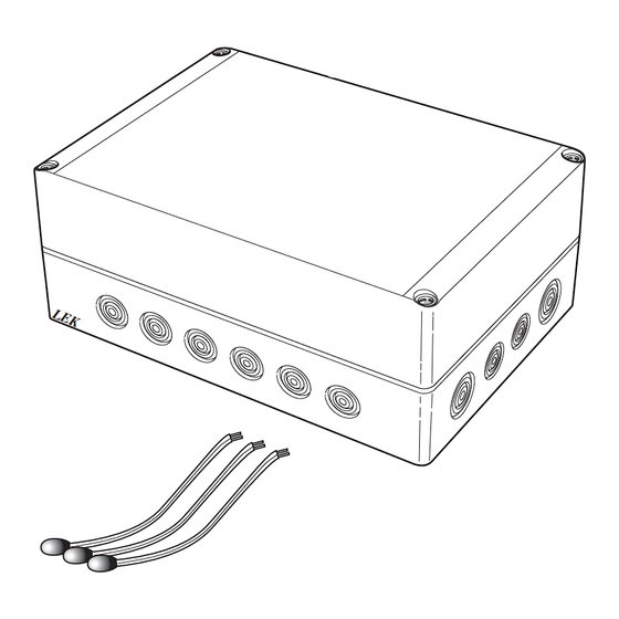
Komponentplacering apparatlåda (AA25) ning. Allmänt ACS 45 är ett tillbehör som möjliggör för din värmepump att styra produktion av värme och kyla oberoende av varandra. AA7-X2 Utöver detta tillbehör (beroende på systemlösning) kan växelventil för kyla, cirkulationspump, shuntventil samt... - Page 4 (normalt öppen, motor i viloläge). Cirkulationspump, värmedump Montera cirkulationspumpen (GP20) efter shuntventilen för värmedump (QN36) på framledningen till fläktkon- vektorn. Volymkärl Montera volymkärlet (CP21) för kyla på mellan växelventil (QN12), shuntventil (QN18) och kylsystemet. ACS 45 | SE...
- Page 5 RM10 - RM13 Backventil EP25 Kylsystem Temperaturgivare, framledning EP25 Fläktkonvektor GP20 Cirkulationspump QN25 Shuntventil Passiv/aktiv kyla 4-rör AA25 Apparatlåda med tillbehörskort (ACS 45) BT57 Temperaturgivare, kollektor BT64 Temperaturgivare, framledning kyla BT75 Temperaturgivare, framledning efter vär- medump CP21 Volymkärl, kyla EP24 Fläktkonvektor GP20 Cirkulationspump, värmedump...
- Page 6 Principschema F1145/F1155 med ACS 45 och passiv/aktiv kyla (4-rör) -EQ1 -EP24 -GP20 -QN36 -CP20 -EQ1 -EQ1 -BT75 -RM22 -GP10 -EB100 -BT1 -EQ1 -AA25 -BP6 -QM21 -FL4 -CM2 -EP25 -QM31 -QM32 -XL15 -EP25 -BT2 -BT64 -QN25 -CP21 -GP20 -QM34 -EB100-HQ1 -CP10...
- Page 7 Principschema F1345 med ACS 45 och passiv/aktiv kyla (4-rör) Principschema F1355 med ACS 45 och passiv/aktiv kyla (4-rör) -QZ3 -QZ5 -QZ2 -QZ4 ACS 45 | SE...
- Page 8 -AA101 -X10 1 2 3 4 Värmepumpen ska vara spänningslös vid instal- lation av ACS 45. Elkopplingsversioner F1345 F1345 har olika elinkopplingar beroende på när värme- pumpen tillverkades. För att se vilken elinkoppling som F1345 utan 2.0 F1345 med 2.0/F1355...
- Page 9 En extra temperaturgivare (rumsgivare för kyla) kan kopplas till värmepumpen för att bättre kunna avgöra när det är dags att byta mellan kyl- och värmedrift. För inkoppling av BT74 se respektive produkts IHB. Använd en 2-ledare med minst 0,5 mm² kabelarea. ACS 45 | SE...
- Page 10 Möjlighet finns till extern kyllägesindikering genom relä- Apparatlåda Externt funktion via ett potentialfritt växlande relä (max 2 A) på kopplingsplint X5. Ansluts kyllägesindikering till kopplingsplint X5 måste det väljas i meny 5.4. Öppna SH + Stäng SH - QN18 AA5-X9 ACS 45 | SE...
-
Page 11: Tekniska Uppgifter
Meny 4.9.2 - autolägesinställning Programinställningar Om värmepumpens driftläge är satt till "auto" väljer den Programinställningen av ACS 45 kan göras via startgui- själv, beroende på medelutetemperatur, när start och den eller direkt i menysystemet. stopp av tillsats samt värmeproduktion respektive kyldrift ska tillåtas. -
Page 12: Pipe Connections
Component location unit box (AA25) ing your installation. General ACS 45 is an accessory that makes it possible for your heat pump to control the production of heating and cooling independently of each other. AA7-X2... - Page 13 Install the circulation pump (GP20) after the shunt valve for the heating dump (QN36) on the supply line to the fan coil. Volume vessel Install the volume vessel (CP21) for cooling between re- versing valve (QN12), shunt valve (QN18) and cooling system. ACS 45 | GB...
-
Page 14: Outline Diagrams
Temperature sensor, flow pipe EP25 Fan convectors GP20 Circulation pump QN25 Shunt valve Passive/active cooling 4-pipe AA25 Unit box with accessory card (ACS 45) BT57 Temperature sensor, collector BT64 Temperature sensor, flow line cooling BT75 Temperature sensor, flow line after heat dump CP21... - Page 15 -CP21 -GP20 -QM34 -EB100-HQ1 -CP10 -EB100 -BT7 -FL2 -QN12 -BT57 -CM1 -EB100 -BT6 -QN18 -EP12 Outline diagram F1245/F1255 with ACS 45 and passive/active cooling (4 pipe) -EQ1 -EP24 -GP20 -QN36 -EQ1 -CP20 -EQ1 -BT75 -GP10 -RM22 -EQ1 -AA25 -BP6 -FL4...
- Page 16 Outline diagram F1345 with ACS 45 and passive/active cooling (4 pipe) Outline diagram F1355 with ACS 45 and passive/active cooling (4 pipe) -QZ3 -QZ5 -QZ2 -QZ4 ACS 45 | GB...
-
Page 17: Electrical Connection
(terminal block AA3-X4) in F1145/F1155/F1245/F1255, on terminal block X6 in Connecting the supply Connect the power supply to terminal block X1 as illus- trated. Unit box External 230V 50Hz ACS 45 | GB... - Page 18 To connect BT74 see the respective product's IHB Use a 2 core cable with a cable area of at least 0,5 mm². ACS 45 | GB...
- Page 19 (max. 2 A) on the terminal block X5. If cooling mode indication is connected to terminal block X5, it must be selected in menu 5.4. Open SH + Close SH - QN18 AA5-X9 ACS 45 | GB...
-
Page 20: Program Settings
Program settings When heat pump operating mode is set to "auto“ it se- Program setting of ACS 45 can be performed via the start lects when start and stop of additional heat, heat pro- guide or directly in the menu system. - Page 21 Position der Komponenten im Gerätegehäuse ten sind. (AA25) Allgemeines Mit dem Zubehör ACS 45 kann Ihre Wärmepumpe die Erzeugung von Wärme und Kälte unabhängig voneinan- der steuern. Neben diesem Zubehör (je nach Systemlösung) kann ein Umschaltventil für Kühlung, Umwälzpumpe, Mischventil AA7-X2 und Kühlverteilersystem erforderlich sein.
- Page 22 Verbinden Sie den Rücklauf vom Gebläsekonvektor ■ Fühler- und Kommunikationskabel dürfen nicht mit dem Vorlauf zum Klimatisierungssystem über ein T-Rohr mit dem Anschluss B des Mischventils (schließt in der Nähe von Starkstromleitungen verlegt bei Schließersignal). werden. ACS 45 | DE...
- Page 23 (ACS 45) BT57 Fühler, Kollektor BT64 Vorlauffühler Kühlung BT75 Vorlauffühler hinter der Wärmeableitungs- vorrichtung CP21 Pufferspeicher, Kühlung EP24 Kälteverbraucher GP20 Umwälzpumpe, Wärmeableitung QN12 Umschaltventil, Kühlung/Heizung QN18 Mischventil, Kühlableitung QN36 Mischventil, Wärmeableitung RM22 Rückschlagventil Sonstiges Manometer, Wärmequellenseite Brauchwasservorlauffühler ACS 45 | DE...
- Page 24 Prinzipskizze F1145/F1155 mit ACS 45 und passiver/aktiver Vierrohrkühlung -EQ1 -EP24 -GP20 -QN36 -CP20 -EQ1 -EQ1 -BT75 -RM22 -GP10 -EB100 -BT1 -EQ1 -AA25 -BP6 -QM21 -FL4 -CM2 -EP25 -QM31 -QM32 -XL15 -EP25 -BT2 -BT64 -QN25 -CP21 -GP20 -QM34 -EB100-HQ1 -CP10 -EB100...
- Page 25 Prinzipskizze F1345 mit ACS 45 und passiver/aktiver Vierrohrkühlung Prinzipskizze F1355 mit ACS 45 und passiver/aktiver Vierrohrkühlung -QZ3 -QZ5 -QZ2 -QZ4 ACS 45 | DE...
-
Page 26: Elektrischer Anschluss
1 2 3 4 gen der Leitungen sind die geltenden Vorschrif- ten zu berücksichtigen. Die Wärmepumpe darf bei der Installation von ACS 45 nicht mit Spannung versorgt werden. Elektroanschlussversionen F1345 F1345 ohne 2.0 F1345 mit 2.0/F1355 F1345 verfügt je nach Herstellungsort der Wärmepumpe über verschiedene elektrische Anschlüsse. - Page 27 Wärmepumpe verbunden werden, damit genau- er ermittelt werden kann, wann zwischen Kühl- und Heizbetrieb umzuschalten ist. Hinweise zum Anschluss von BT74 entnehmen Sie dem jeweiligen IHB-Dokument für das Produkt. Verwenden Sie einen 2-Leiter mit einem Mindestkabel- querschnitt von 0,5 mm². ACS 45 | DE...
- Page 28 Relais (max. 2 A) an Anschlussklemme X5 kann eine ex- terne Kühlmodusanzeige geschaltet werden. Wird die Kühlmodusanzeige mit Anschlussklemme X5 verbunden, muss dies in Menü 5.4 ausgewählt werden. Öffnen SH + Schließen SH - QN18 AA5-X9 ACS 45 | DE...
-
Page 29: Technische Daten
Menü 4.9.2-Automoduseinst. Programmeinstellungen Wenn als Betriebsmodus für die Wärmepumpe "auto" Die Programmeinstellung von ACS 45 kann per Startas- eingestellt ist, bestimmt die Wärmepumpe ausgehend sistent oder direkt im Menüsystem vorgenommen wer- von der mittleren Außenlufttemperatur selbst, wann den. Start und Stopp der Zusatzheizung sowie Brauchwasser- bereitung bzw. - Page 30 Wiring diagram ACS 45 |...
- Page 32 WS name: -Gemensamt WS version: a343 WS release date: 2017-04-04 08:10 Publish date: 2017-04-27 15:35 NIBE AB Sweden Hannabadsvägen 5 Box 14 SE-285 21 Markaryd info@nibe.se www.nibe.eu 431285...
Need help?
Do you have a question about the ACS 45 and is the answer not in the manual?
Questions and answers