Nibe AXC 40 Installer Manual
Accessory card
Hide thumbs
Also See for AXC 40:
- Installer manual (64 pages) ,
- Installer manual (36 pages) ,
- Installer manual (60 pages)
Table of Contents
Advertisement
Quick Links
Advertisement
Table of Contents

Related Manuals for Nibe AXC 40


Summary of Contents for Nibe AXC 40
- Page 1 AXC 40 Installer Manual Accessory card IHB 2236-1 731176...
- Page 2 S-series F-series S1255 S-series F-series...
-
Page 3: Table Of Contents
General Common electrical connection Shunt controlled additional heat Step controlled additional heat Hot water comfort Ground water system Shunt controlled brine Hybrid connection - charge pumps Hybrid connection - reversing valves Pulse energy meter Technical data Contact information AXC 40... -
Page 4: Important Information
Cleaning and user maintenance shall not be made by children without supervision. This is an original manual. It may not be translated without the approval of NIBE. Rights to make any design or technical modifications are reserved. ©NIBE 2022. -
Page 5: General
General COMPONENT LOCATION, AXC MODULE (AA25) This accessory is used to enable connection and control of AA5-X4 AA5-S2 the following accessory functions. One AXC 40 is required for each function. • shunt-controlled additional heat • step-controlled additional heat • control of circulation pump for hot water circulation •... -
Page 6: Common Electrical Connection
0.5 mm² up to 50 m, for example EKKX, LiYY or equivalent. • AXC 40 must be installed via an isolator switch. The cable area has to be dimensioned based on the fuse rating used. •... - Page 7 CONNECTING COMMUNICATION AXC 40 contains an accessory board (AA5) that connects directly to the main product’s PCB (terminal block AA2-X30). If several accessories are to be connected, or are already installed, the boards are connected in series. Because there can be different connections for accessories...
-
Page 8: Shunt Controlled Additional Heat
The heat pump/indoor module controls a shunt valve (EM1- line to the climate system after the heat pump according to QN11) and a circulation pump (EM1-GP10) via AXC 40. If the the outline diagram. heat pump/indoor module cannot manage to maintain the •... - Page 9 External AA25 24 23 22 21 20 19 18 17 16 15 14 13 AA5-X2 Caution The relay outputs on the accessory board can have a max load of 2 A (230 V) in total. AXC 40 S-series | EN...
- Page 10 Connection of 0-10 V control of shunt motor (EM1-QN11) Connect a 2-core cable to AA5-X2:5 (0-10 V) and AA5-X2:6 (GND). External AA25 7 6 5 4 AA5-X2 At 0 V the shunt is closed and at 10 V the shunt is open. AXC 40 S-series | EN...
- Page 11 PROGRAM SETTINGS NOTE Activating AXC 40 can be performed via the start guide or directly in the menu system. Forced control is only intended to be used for troubleshooting purposes. Using the function in The main product’s software must be the latest version.
- Page 12 ELECTRICAL CIRCUIT DIAGRAM AXC 40 S-series | EN...
-
Page 13: Step Controlled Additional Heat
This is an outline diagram. Actual installations must electric boiler, to aid with heating. be planned according to applicable standards. With AXC 40, three potential-free relays can be used for EXPLANATION additional heat control, which then gives max. 3 linear or 7 binary steps. - Page 14 2 A (230 V) in total. CONNECTING HEATING MEDIUM PUMP (EB1-GP10) Connect the external heating medium pump (GP10) to AA5- X9:8 (230 V), AA5-X9:7 (N) and X1:3 (PE). AA25 External AA5-X9 GP10 AA25-X1 AXC 40 S-series | EN...
- Page 15 PROGRAM SETTINGS NOTE Activating AXC 40 can be performed via the start guide or directly in the menu system. Forced control is only intended to be used for troubleshooting purposes. Using the function in The main product’s software must be the latest version.
- Page 16 ELECTRICAL CIRCUIT DIAGRAM AXC 40 S-series | EN...
-
Page 17: Hot Water Comfort
Heat pump Temperature sensor, hot water Temperature sensor, hot water top OUTLINE DIAGRAM WITH ADDITIONAL WATER HEATER, HWC AND ELECTRONIC MIXING VALVE -EB100 -QZ1 -QZ1-AA25 -QZ1-FQ3 -QZ1-BT70 -BT82 -QZ1-RN1 -QZ1-RM1 -QZ1-GP11 -CP1 -EB100-BT7 -CP2 -QZ1-BT83 -EB100-BT6 AXC 40 S-series | EN... - Page 18 Connect the sensor to AA5-X2:19-20. Connect the circulation pump (GP11) to AA5-X9:8 (230 V), AA5-X9:7 (N) and X1:. BT83 AA25 External AA5-X9 GP11 External AA25 24 23 22 21 20 19 18 17 16 15 14 13 AA25-X1 AA5-X2 AXC 40 S-series | EN...
- Page 19 CONNECTION OF THE MIXER VALVE (QZ1-FQ3) PROGRAM SETTINGS Connect the mixing valve motor (FQ3) to AA5-X9:6 (230 V, Activating AXC 40 can be performed via the start guide or open), AA5-X9:5 (N) and AA5-X9:4 (230 V, close). directly in the menu system.
- Page 20 Activating mixing valve: Activated if mixer valve is installed and it is to be controlled from AXC 40. When the option is active, you can set the outgoing hot water temperature, shunt amplification and shunt waiting time for the mixer valve.
- Page 21 ELECTRICAL CIRCUIT DIAGRAM AXC 40 S-series | EN...
-
Page 22: Ground Water System
EB100 Heat pump GENERAL BT57 Brine sensor, supply line With AXC 40 a ground water pump can be connected to the BT58 Brine sensor, return line heat pump if the software controlled output (AUX output) OUTLINE DIAGRAM WITH GROUNDWATER is used for something else. - Page 23 When the contact closes, the groundwater pump is blocked. 7 6 5 4 AA5-X2 Pump speed EP12-GP3 100 % approx 0 V DC 50 % approx 5 V DC approx 10 V DC AXC 40 S-series | EN...
- Page 24 DIP SWITCH PROGRAM SETTINGS The DIP switch (S2) on the accessory board (AA5) must be Activating AXC 40 can be performed via the start guide or set as follows. directly in the menu system. The main product’s software must be the latest version.
- Page 25 ELECTRICAL CIRCUIT DIAGRAM AXC 40 S-series | EN...
-
Page 26: Shunt Controlled Brine
Electrical installation and wiring must be carried out in accordance with national provisions. NOTE The main product must be disconnected from the power supply when installing AXC 40. To prevent interference, sensor cables to external connections must not be laid close to high voltage cables. - Page 27 2 A (230 V) in total. CONNECTION OF SHUNT MOTOR (EP10-QN41) Connect the shunt motor (QN41) to AA5-X9:6 (230 V, open), AA5-X9:5 (N) and AA5-X9:4 (230 V, close). External AA25 AA5-X9 QN41 Open SH + Close SH - AXC 40 S-series | EN...
- Page 28 PROGRAM SETTINGS Activating AXC 40 can be performed via the start guide or directly in the menu system. The main product’s software must be the latest version. START GUIDE The start guide appears upon first start-up after heat pump installation, but is also found in menu 7.7.
- Page 29 ELECTRICAL CIRCUIT DIAGRAM AXC 40 S-series | EN...
-
Page 30: Hybrid Connection - Charge Pumps
A CPD type charge pump is recommended to allow the use GP12.2 Charge pump of speed control, which guarantees correct delta-t in the Miscellaneous various operating modes during the year. AXC 40 also en- Water heater ables external blocking of each associated subordinate heat Non-return valve pump. - Page 31 An additional switch can be connected to AA5-X2:15-16 to allow blocking of the heat pump(s). When the contact closes, the heat pump(s) -EB10X is blocked. External blocking External AA25 24 23 22 21 20 19 18 17 16 15 14 13 AA5-X2 AXC 40 S-series | EN...
- Page 32 Operating mode Charge pump AA5-X2 Alternatives: Auto, Intermittent Auto: The charge pump runs according to the current oper- ating mode for AXC 40. -EB10Y-GP12.Y Intermittent: The charge pump starts 20 seconds before the compressor starts and it is turned off 20 seconds after the compressor stops.
- Page 33 Manual speed: If you have chosen to control the charge pump manually, you set the desired pump speed here. (Settings are available per demand heating/pool/hot water.) Caution Also see the Installer Manual for the main product. AXC 40 S-series | EN...
- Page 34 ELECTRICAL CIRCUIT DIAGRAM AXC 40 S-series | EN...
-
Page 35: Hybrid Connection - Reversing Valves
Ground source heat pump This function allows control of up to two reversing valves. AA25 AXC module It is possible to use the same AXC 40 (AA25) for both charge BT25 External supply temperature sensor pump (GP12) and reversing valve (QN10). - Page 36 AA5-X9 -EB10X-QN10.X Brown Blue Black AA5-X10 Connection of reversing valve (QN10.Y) Connect the reversing valve motor (EB10Y-QN10.Y) to AA5- X9:8 (signal), AA5-X9:7 (N) and AA5-X10:2 (230 V). AA25 External AA5-X9 -EB10Y-QN10.Y Brown Blue Black AA5-X10 AXC 40 S-series | EN...
- Page 37 Workspace for docking: The system docking is drawn here. Marking frame: Press the marking frame you want to change. Select one of the selectable components. AXC 40 S-series | EN...
- Page 38 ELECTRICAL CIRCUIT DIAGRAM AXC 40 S-series | EN...
-
Page 39: Pulse Energy Meter
BE16 Electrical installation and wiring must be carried out in accordance with national provisions. BE15 AA5-X2 The main product must be disconnected from the power supply when installing AXC 40. BE14 BE13 NOTE Read section "Common electrical connection" for BE12 instructions regarding electrical connection. - Page 40 PROGRAM SETTINGS Activating AXC 40 can be performed via the start guide or directly in the menu system. The main product’s software must be the latest version. START GUIDE The start guide appears upon first start-up after heat pump installation, but is also found in menu 7.7.
-
Page 41: Technical Data
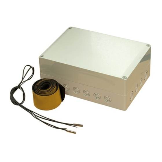
Program cycles, hours 1, 24 Program cycles, days 1, 2, 5, 7 Resolution, program min. Temperature during ball pressure test according to EN 60 730-1 °C Dimensions LxWxH 175x250x100 Weight 1.47 AXC 40 Part No. 067 060 AXC 40 S-series | EN... -
Page 42: Contact Information
F-series Table of Contents F-series Important information General Common electrical connection Shunt controlled additional heat Step controlled additional heat Hot water comfort Ground water system Shunt controlled brine Pulse energy meter Technical data Contact information AXC 40 S-series... - Page 43 Cleaning and user maintenance shall not be made by children without supervision. This is an original manual. It may not be translated without the approval of NIBE. Rights to make any design or technical modifications are reserved. ©NIBE 2022.
- Page 44 General COMPONENT LOCATION, AXC MODULE (AA25) This accessory is used to enable connection and control of AA5-X4 AA5-S2 the following accessory functions. One AXC 40 is required for each function. • shunt-controlled additional heat • step-controlled additional heat • control of circulation pump for hot water circulation •...
- Page 45 0.5 mm² up to 50 m, for example EKKX, LiYY or equivalent. • AXC 40 must be installed via an isolator switch. The cable area has to be dimensioned based on the fuse rating used. •...
- Page 46 CONNECTING COMMUNICATION AXC 40 contains an accessory board (AA5) that connects directly to the main product’s input board (terminal block AA3-X4). If several accessories are to be connected, or are already installed, the boards are connected in series. Because there can be different connections for accessories...
- Page 47 The heat pump/indoor module controls a shunt valve (EM1- line to the climate system after the heat pump according to QN11) and a circulation pump (EM1-GP10) via AXC 40. If the the outline diagram. heat pump/indoor module cannot manage to maintain the •...
- Page 48 External AA25 24 23 22 21 20 19 18 17 16 15 14 13 AA5-X2 Caution The relay outputs on the accessory board can have a max load of 2 A (230 V) in total. AXC 40 F-series | EN...
- Page 49 Connection of 0-10 V control of shunt motor (EM1-QN11) Connect a 2-core cable to AA5-X2:5 (0-10 V) and AA5-X2:6 (GND). External AA25 7 6 5 4 AA5-X2 At 0 V the shunt is closed and at 10 V the shunt is open. AXC 40 F-series | EN...
- Page 50 PROGRAM SETTINGS Activating AXC 40 can be performed via the start guide or directly in the menu system. START GUIDE The start guide appears upon first start-up after heat pump installation, but is also found in menu 5.7. MENU SYSTEM...
- Page 51 ELECTRICAL CIRCUIT DIAGRAM AXC 40 F-series | EN...
- Page 52 This is an outline diagram. Actual installations must electric boiler, to aid with heating. be planned according to applicable standards. With AXC 40, three potential-free relays can be used for EXPLANATION additional heat control, which then gives max. 3 linear or 7 binary steps.
- Page 53 2 A (230 V) in total. CONNECTING HEATING MEDIUM PUMP (EB1-GP10) Connect the external heating medium pump (GP10) to AA5- X9:8 (230 V), AA5-X9:7 (N) and X1:3 (PE). AA25 External AA5-X9 GP10 AA25-X1 AXC 40 F-series | EN...
- Page 54 PROGRAM SETTINGS Activating AXC 40 can be performed via the start guide or directly in the menu system. START GUIDE The start guide appears upon first start-up after heat pump installation, but is also found in menu 5.7. MENU SYSTEM...
- Page 55 ELECTRICAL CIRCUIT DIAGRAM AXC 40 F-series | EN...
- Page 56 Heat pump Temperature sensor, hot water Temperature sensor, hot water top OUTLINE DIAGRAM WITH ADDITIONAL WATER HEATER, HWC AND ELECTRONIC MIXING VALVE -EB100 -QZ1 -QZ1-AA25 -QZ1-FQ3 -QZ1-BT70 -BT82 -QZ1-RN1 -QZ1-RM1 -QZ1-GP11 -CP1 -EB100-BT7 -CP2 -QZ1-BT83 -EB100-BT6 AXC 40 F-series | EN...
- Page 57 Connect the circulation pump (GP11) to AA5-X9:8 (230 V), AA5-X9:7 (N) and X1:3 (PE). BT83 AA25 External AA5-X9 GP11 External AA25 24 23 22 21 20 19 18 17 16 15 14 13 AA25-X1 AA5-X2 AXC 40 F-series | EN...
- Page 58 CONNECTION OF THE MIXER VALVE (QZ1-FQ3) PROGRAM SETTINGS Connect the mixing valve motor (FQ3) to AA5-X9:6 (230 V, Activating AXC 40 can be performed via the start guide or open), AA5-X9:5 (N) and AA5-X9:4 (230 V, close). directly in the menu system.
- Page 59 ELECTRICAL CIRCUIT DIAGRAM AXC 40 F-series | EN...
- Page 60 Ground water system Heat exchanger, groundwater HQ40 Particle filter GENERAL Groundwater pump With AXC 40 a ground water pump can be connected to the EB100 Heat pump heat pump if the software controlled output (AUX output) BT57 Brine sensor, supply line is used for something else.
- Page 61 A contact (NO) can be connected to AA5-X2:21-22 to block the groundwater pump. When the contact closes, the Pump speed EP12-GP3 groundwater pump is blocked. 100 % approx 0 V DC 50 % approx 5 V DC approx 10 V DC AXC 40 F-series | EN...
- Page 62 The DIP switch (S2) on the accessory board (AA5) must be set as follows. PROGRAM SETTINGS Activating AXC 40 can be performed via the start guide or directly in the menu system. START GUIDE The start guide appears upon first start-up after heat pump installation, but is also found in menu 5.7.
- Page 63 ELECTRICAL CIRCUIT DIAGRAM AXC 40 F-series | EN...
- Page 64 The main product must be disconnected from the NOTE power supply when installing AXC 40. To prevent interference, sensor cables to external connections must not be laid close to high voltage cables.
- Page 65 2 A (230 V) in total. CONNECTION OF SHUNT MOTOR (EP10-QN41) Connect the shunt motor (QN41) to AA5-X9:6 (230 V, open), AA5-X9:5 (N) and AA5-X9:4 (230 V, close). External AA25 AA5-X9 QN41 Open SH + Close SH - AXC 40 F-series | EN...
- Page 66 PROGRAM SETTINGS Activating AXC 40 can be performed via the start guide or directly in the menu system. START GUIDE The start guide appears upon first start-up after heat pump installation, but is also found in menu 5.7. MENU SYSTEM...
- Page 67 ELECTRICAL CIRCUIT DIAGRAM AXC 40 F-series | EN...
- Page 68 Electrical installation and wiring must be carried BE14 out in accordance with national provisions. BE13 The main product must be disconnected from the power supply when installing AXC 40. BE12 NOTE BE11 Read section "Common electrical connection" for instructions regarding electrical connection.
- Page 69 PROGRAM SETTINGS Activating AXC 40 can be performed via the start guide or directly in the menu system. START GUIDE The start guide appears upon first start-up after heat pump installation, but is also found in menu 5.7. MENU SYSTEM...
- Page 70 Program cycles, hours 1, 24 Program cycles, days 1, 2, 5, 7 Resolution, program min. Temperature during ball pressure test according to EN 60 730-1 °C Dimensions LxWxH 175x250x100 Weight 1.47 AXC 40 Part No. 067 060 AXC 40 F-series | EN...
- Page 71 POLAND SWEDEN SWITZERLAND NIBE-BIAWAR Sp. z o.o. NIBE Energy Systems NIBE Wärmetechnik c/o ait Schweiz AG Al. Jana Pawla II 57, 15-703 Bialystok Box 14 Industriepark, CH-6246 Altishofen Tel: +48 (0)85 66 28 490 Hannabadsvägen 5, 285 21 Markaryd Tel.
- Page 72 WS release date: 2022-09-12 12:50 Publish date: 2022-09-28 06:57 This is a publication from NIBE Energy Systems. All product illustrations, facts and data are based on the available information at the time of the publication’s approval. NIBE Energy Systems makes reservations for any factual or printing errors in this publication.
Need help?
Do you have a question about the AXC 40 and is the answer not in the manual?
Questions and answers