Nibe ACS 45 Installer Manual
Passive / active cooling (4 pipe) for nibe f1145, nibe f1155, nibe f1245, nibe f1255, nibe f1345
Hide thumbs
Also See for ACS 45:
- Installer manual (92 pages) ,
- Installer manual (60 pages) ,
- Installer manual (32 pages)
Table of Contents
Advertisement
Available languages
Available languages
Quick Links
Installatörshandbok Passiv/aktiv kyla (4-rör)
SE
för NIBE F1145, F1155, F1245, F1255, F1345
Installer manual Passive/active cooling (4 pipe)
GB
for NIBE F1145, F1155, F1245, F1255, F1345
Installateurhandbuch Passiver/aktiver
DE
Vierrohrkühlung für NIBE F1145, F1155, F1245,
F1255, F1345
ACS 45
IHB 1510-2
431285
Advertisement
Table of Contents

Subscribe to Our Youtube Channel
Related Manuals for Nibe ACS 45


Summary of Contents for Nibe ACS 45
- Page 1 ACS 45 Installatörshandbok Passiv/aktiv kyla (4-rör) för NIBE F1145, F1155, F1245, F1255, F1345 Installer manual Passive/active cooling (4 pipe) for NIBE F1145, F1155, F1245, F1255, F1345 Installateurhandbuch Passiver/aktiver Vierrohrkühlung für NIBE F1145, F1155, F1245, F1255, F1345 IHB 1510-2 431285...
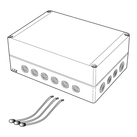
- Page 3 Svenska, IHB - ACS 45 Komponentplacering apparatlåda (AA25) Allmänt ACS 45 är ett tillbehör som möjliggör för din värme- pump att styra produktion av värme och kyla oberoen- de av varandra. Utöver detta tillbehör (beroende på systemlösning) kan växelventil för kyla, cirkulationspump, shuntventil samt distributionssystem för kyla behövas.
- Page 4 Cirkulationspump, värmedump Röranslutning Montera cirkulationspumpen (GP20) efter shuntventi- len för värmedump (QN36) på framledningen till Allmänt fläktkonvektorn. För att undvika kondensbildning måste rörledningar och övriga kalla ytor isoleras med diffusionstätt mate- Volymkärl rial. Vid stort kylbehov krävs fläktkonvektor med Montera volymkärlet (CP21) för kyla på mellan växel- droppskål och avloppsanslutning.
- Page 5 Principschemor GP20 Cirkulationspump QN25 Shuntventil Passiv/aktiv kyla 4-rör OBS! AA25 Apparatlåda med tillbehörskort (ACS 45) Dessa är principscheman. BT57 Temperaturgivare, kollektor Verklig anläggning skall projekteras enligt BT64 Temperaturgivare, framledning kyla gällande normer. BT75 Temperaturgivare, framledning efter värmedump Förklaring CP21 Volymkärl, kyla...
- Page 6 Principschema F1145/F1155 med ACS 45 och passiv/aktiv kyla (4-rör) -EQ1 -EP24 -GP20 -QN36 -CP20 -EQ1 -EQ1 -BT75 -RM22 -GP10 -EB100 -BT1 -EQ1 -AA25 -BP6 -QM21 -FL4 -CM2 -EP25 -QM31 -QM32 -XL15 -EP25 -BT2 -BT64 -QN25 -CP21 -GP20 -QM34 -EB100-HQ1 -CP10...
- Page 7 Principschema F1345 med ACS 45 och passiv/aktiv kyla (4-rör)
- Page 8 All elektrisk inkoppling skall ske av behörig elektriker. Elektrisk installation och ledningsdragning skall utföras enligt gällande bestämmelser. Värmepumpen ska vara spänningslös vid instal- lation av ACS 45. F1345 utan 2.0 F1345 med 2.0 Elschema finns i slutet av denna installatörshandbok. AA3-X4...
- Page 9 Anslutning av matning Extern blockering, passiv kyla (valfritt) Anslut spänningsmatningen till plint X1 enligt bild. En kontakt (NO) kan anslutas till AA5-X2:13-14 för att kunna blockera passiv kyla. När kontakten sluts blocke- Apparatlåda Externt ras passiv kyla. 230V 50Hz Extern blockering, aktiv kyla (valfritt) En kontakt (NO) kan anslutas till AA5-X2:15-16 för att kunna blockera aktiv kyla.
- Page 10 Anslutning av cirkulationspump, vär- Anslutning av shuntmotor (QN36) medump (GP20) Anslut shuntmotorn (QN36) till AA7-X2:4 (230 V, öppna), AA5-X10:1 (N) och AA7-X2:2 (230 V, stäng). Anslut cirkulationspumpen (GP20) till AA5-X9:8 (230 V), AA5-X9:7 (N) och jord (PE). Apparatlåda Externt Apparatlåda Externt AA7-X2 1 2 3 4 5 6...
- Page 11 Meny 4.9.2 - autolägesinställning Programinställningar Om värmepumpens driftläge är satt till "auto" väljer Programinställningen av ACS 45 kan göras via startgui- den själv, beroende på medelutetemperatur, när start den eller direkt i menysystemet. och stopp av tillsats samt värmeproduktion respektive kyldrift ska tillåtas.
-
Page 12: Compatible Products
English, IHB, ACS 45 Component location unit box (AA25) General ACS 45 is an accessory that makes it possible for your heat pump to control the production of heating and cooling independently of each other. In addition to this accessory (depending on system... -
Page 13: Pipe Connections
Circulation pump, heat dump Pipe connections Install the extra circulation pump (GP20) after the mixing valve for the heat dump (QN36) on the flow General line to the convection fan. Pipes and other cold surfaces must be insulated with diffusion-proof material to prevent condensation. Volume vessel Where the cooling demand is high, fan convectors with Install the volume vessel (CP21) for cooling between... -
Page 14: Outline Diagrams
Outline diagrams Passive/active cooling 4-pipe AA25 Unit box with accessory card (ACS 45) BT57 Temperature sensor, collector NOTE BT64 Temperature sensor, flow line cooling These are outline diagrams. BT75 Temperature sensor, flow line after heat Actual installations must be planned according dump to applicable standards. - Page 15 -CP21 -GP20 -QM34 -EB100-HQ1 -CP10 -EB100 -BT7 -FL2 -QN12 -BT57 -CM1 -EB100 -BT6 -QN18 -EP12 Outline diagram F1245/F1255 with ACS 45 and passive/active cooling (4 pipe) -EQ1 -EP24 -GP20 -QN36 -EQ1 -CP20 -EQ1 -BT75 -GP10 -RM22 -EQ1 -AA25 -BP6 -FL4...
- Page 16 Outline diagram F1345 with ACS 45 and passive/active cooling (4 pipe)
-
Page 17: Electrical Connection
The heat pump must not be powered when F1345 without2.0 F1345 with2.0 installing ACS 45. AA3-X4 The electrical circuit diagram is at the end of this In- AA3-X4 staller handbook. Connecting communication... - Page 18 Connecting the supply External blocking, passive cooling (optional) Connect the power supply to terminal block X1 as illus- A contact (NO) can be connected to AA5-X2:13-14 to trated. block passive cooling operation. When the contact closes, passive cooling is blocked. Unit box External External blocking, active cooling (optional)
- Page 19 Connection of the circulation pump, heat Connection of the mixing valve motor dump (GP20) (QN36) Connect the circulation pump (GP20) to AA5-X9:8 (230 Connect mixing motor (QN36) to AA7-X2:4 (230 V, V), AA5-X9:7 (N) and ground (PE). open), AA5-X10:1 (N) and AA7-X2:2 (230 V, close). Unit box External Unit box External...
-
Page 20: Program Settings
Menu 4.9.2 - auto mode setting Program settings When heat pump operating mode is set to "auto“ it Program setting of ACS 45 can be performed via the selects when start and stop of additional heat, heat start guide or directly in the menu system. - Page 21 Deutsch, IHB - ACS 45 Position der Komponenten im Gerätegehäu- Allgemeines se (AA25) Mit dem Zubehör ACS 45 kann Ihre Wärmepumpe die Erzeugung von Wärme und Kälte unabhängig vonein- ander steuern. Neben diesem Zubehör (je nach Systemlösung) kann ein Umschaltventil für Kühlung, Umwälzpumpe, Mischventil und Kühlverteilersystem erforderlich sein.
- Page 22 Umschaltventil, Kühlung/Heizung Rohranschluss/Durchflussmes- Das Umschaltventil (QN12) wird gemäß Prinzipskizze im Wärmequellensystem am Vorlauf von der Wärme- pumpe montiert. Allgemeines Verbinden Sie den Vorlauf des Kühlsystems ■ mit dem Anschluss A des Umschaltventils Um eine Kondensatbildung zu vermeiden, müssen (öffnet bei Signal). Rohrleitungen und andere kalte Oberflächen mit diffu- Verbinden Sie den wärmepumpenseitigen ■...
- Page 23 Prinzipskizzen Passive/aktive Vierrohrkühlung AA25 Gerätegehäuse mit Zubehörplatine (ACS 45) HINWEIS! BT57 Fühler, Kollektor Dies sind Prinzipskizzen. BT64 Vorlauffühler Kühlung Die tatsächliche Anlage muss gemäß den gel- BT75 Vorlauffühler hinter der Wärmeablei- tenden Normen geplant und montiert werden. tungsvorrichtung CP21 Pufferspeicher, Kühlung Erklärung...
- Page 24 Prinzipskizze F1145/F1155 mit ACS 45 und passiver/aktiver Vierrohrkühlung -EQ1 -EP24 -GP20 -QN36 -CP20 -EQ1 -EQ1 -BT75 -RM22 -GP10 -EB100 -BT1 -EQ1 -AA25 -BP6 -QM21 -FL4 -CM2 -EP25 -QM31 -QM32 -XL15 -EP25 -BT2 -BT64 -QN25 -CP21 -GP20 -QM34 -EB100-HQ1 -CP10 -EB100...
- Page 25 Prinzipskizze F1345 mit ACS 45 und passiver/aktiver Vierrohrkühlung...
-
Page 26: Elektrischer Anschluss
Leitungen sind die geltenden Vorschriften zu berücksichtigen. Die Wärmepumpe darf bei der Installation von F1345 ohne 2.0 F1345 mit 2.0 ACS 45 nicht mit Spannung versorgt werden. AA3-X4 Der Schaltplan befindet sich am Ende dieses Installa- AA3-X4 teurhandbuchs. Anschluss der Kommunikationsleitung Soll weiteres Zubehör angeschlossen werden oder ist... - Page 27 Anschluss der Spannungsversorgung Externe Blockierung, passive Kühlung (beliebig) Verbinden Sie die Spannungsversorgung mit Anschluss- Um den Passivkühlbetrieb zu blockieren kann AA5- klemme X1, siehe Abbildung. X2:13-14 mit einem potentialfreien Schaltkontakt ver- bunden werden. Beim Schließen des Kontakts wird die Gerätegehäuse Extern passive Kühlung blockiert.
-
Page 28: Dip-Schalter
Anschluss der Umwälzpumpe, Wärmeablei- Anschluss des Mischventilmotors (QN36) tung (GP20) Verbinden Sie den Mischventilmotor (QN36) mit AA7- X2:4 (230 V, öffnen), AA5-X10:1 (N) und AA7-X2:2 (230 Verbinden Sie die Umwälzpumpe (GP20) mit AA5-X9: V, schließen). 8 (230 V), AA5-X9:7 (N) und Erdung (PE). Gerätegehäuse Extern Gerätegehäuse Extern... - Page 29 Menü 4.9.2 - Automoduseinst. Programmeinstellungen Wenn als Betriebsmodus für die Wärmepumpe "auto" Die Programmeinstellung von ACS 45 kann per Startas- eingestellt ist, bestimmt die Wärmepumpe ausgehend sistent oder direkt im Menüsystem vorgenommen von der mittleren Außenlufttemperatur selbst, wann werden. Start und Stopp der Zusatzheizung sowie Brauchwas- serbereitung bzw.
- Page 30 Elschema/Electrical wiring diagram/Elektrischer schaltplan...
- Page 32 431285...
Need help?
Do you have a question about the ACS 45 and is the answer not in the manual?
Questions and answers