Nibe ACS 45 Installer Manual
Passive/active cooling (4-pipe)
Hide thumbs
Also See for ACS 45:
- Installer manual (92 pages) ,
- Installer manual (32 pages) ,
- Installer manual (32 pages)
Advertisement
Available languages
Available languages
Quick Links
Advertisement
Chapters

Related Manuals for Nibe ACS 45


Summary of Contents for Nibe ACS 45
- Page 1 IHB 1934-4 431285 ACS 45 Installatörshandbok S1155, S1255 Passiv/aktiv kyla (4-rör) Installer manual Passive/active cooling (4-pipe) F1145, F1155, F1245, F1255, F1345, F1355 Installateurhandbuch Passive/aktive Vierrohrkühlung...
-
Page 3: Table Of Contents
S1155, S1255 Table of Contents Svenska Viktig information Allmänt Röranslutning Principschemor Elinkoppling Programinställningar Tekniska uppgifter English Important information General Pipe connections Outline diagrams Electrical connection Program settings Technical data Kontaktinformation ACS 45 | DE... -
Page 4: Viktig Information
TÄNK PÅ! Vid denna symbol finns viktig information om vad du ska tänka på när du installerar eller ser- var anläggningen. TIPS! Vid denna symbol finns tips om hur du kan underlätta handhavandet av produkten. ACS 45 | SE... -
Page 5: Allmänt
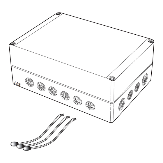
MONTERING Allmänt TÄNK PÅ! ACS 45 är ett tillbehör, som innehåller en fristående Skruvtyp ska anpassas efter underlaget som elektrisk styrmodul,som möjliggör för din värmepump monteringen sker på. att styra produktion av värme och kyla oberoende av varandra. Utöver detta tillbehör (beroende på systemlösning) kan växelventil för kyla, cirkulationspump, shuntventil samt... -
Page 6: Röranslutning
A på växelventilen (öppen vid signal). • Anslut köldbärare ut från värmepumpen till gemensam port AB på växelventilen (alltid öppen). • Anslut köldbärare ut till kollektorn till port B på växel- ventilen (normalt öppen, motor i viloläge). ACS 45 | SE... -
Page 7: Principschemor
Passiv/aktiv kyla 4-rör AA25 AXC-modul BT57 Temperaturgivare, kollektor BT64 Temperaturgivare, framledning kyla BT75 Temperaturgivare, framledning efter vär- medump CP21 Volymkärl, kyla EP24 Fläktkonvektor GP20 Cirkulationspump, värmedump QN12 Växelventil, kyla/värme QN18 Shuntventil, kyldump QN36 Shuntventil, värmedump RM22 Backventil Övrigt ACS 45 | SE... - Page 8 Principschema S1155 med ACS 45 och passiv/aktiv kyla (4-rör) -EQ1 -EP24 -GP20 -QN36 -CP20 -EQ1 -EB100 -EQ1 -BT75 -BT25 -RM22 -GP10 -EB100 -BT1 -EQ1 -AA25 -BP6 -FL4 -QM21 -CM2 -EP25 -QM31 -QM32 -XL15 -EP25 -BT2 -BT64 -QN25 -CP21 -GP20 -QM34...
-
Page 9: Elinkoppling
• Minsta area på kommunikations- och givarkablar till extern anslutning ska vara 0,5 mm² upp till 50 m, till exempel EKKX, LiYY eller liknande. Tillbehör 2 • ACS 45 ska installeras via allpolig brytare. Kabelarea AA5-X4 ska vara dimensionerad efter vilken avsäkring som används. - Page 10 En extra temperaturgivare (rumsgivare för kyla) kan kopplas till värmepumpen för att bättre kunna avgöra när det är dags att byta mellan kyl- och värmedrift. För inkoppling av BT74 se respektive produkts IHB. Använd en 2-ledare med minst 0,5 mm² kabelarea. ACS 45 | SE...
- Page 11 AA5-X9:5 (N) och AA5-X9:4 (230 V, stäng). funktion via ett potentialfritt växlande relä (max 2 A) på Externt ACS 45 kopplingsplint X5. Ansluts kyllägesindikering till kopplingsplint X5 måste det väljas i meny 7.4. Öppna SH + Stäng SH - QN18 AA5-X9 ACS 45 | SE...
-
Page 12: Programinställningar
Programinställningar TIPS! Vänta ett dygn innan du gör en ny inställning, Programinställningen av ACS 45 kan göras via startgui- så att rumstemperaturen hinner stabilisera sig. den eller direkt i menysystemet. Om det är kallt ute och rumstemperaturen är STARTGUIDEN för låg, öka kurvlutningen i meny 1.30.1 ett steg. - Page 13 Fast delta: Här ställer du in om köldbärarpumpen ska regleras med fast delta, t.ex. vid grundvattensystem. Manuellt: Har du valt att styra köldbärarpumpen manuellt ställer du här in önskad pumphastighet. ACS 45 | SE...
- Page 14 Du kan även ställa in under hur lång tid (Filtertid) mede- Extra temperaturgivare kan kopplas till anläggningen för lutetemperaturen räknas. Väljer du 0 innebär det att ak- att avgöra när det är dags att byta mellan värme- och tuell utetemperatur används. kyldrift. ACS 45 | SE...
- Page 15 Här kan du tvångsstyra de olika komponenterna i anlägg- ningen. Dock är de viktigaste skyddsfunktionerna aktiva. OBS! Tvångsstyrning är endast avsett att användas i felsökningssyfte. Att använda funktionen på annat sätt kan medföra skador på ingående komponenter i ditt klimatsystem. ACS 45 | SE...
-
Page 16: Tekniska Uppgifter
Programcykler, timmar 1, 24 Programcykler, dagar 1, 2, 5, 7 Upplösning, program Mått LxBxH 175x250x100 Vikt 1,47 ACS 45 Märkspänning 230V ~ 50Hz Mått (BxDxH) (mm) 250x100x175 Art nr 067 195 RSK nr 624 67 96 ACS 45 | SE... -
Page 17: English
This symbol indicates danger to person or ma- chine . Caution This symbol indicates important information about what you should consider when installing or servicing the installation. This symbol indicates tips on how to facilitate using the product. ACS 45 | GB... -
Page 18: General
MOUNTING General Caution ACS 45 is an accessory that includes a freestanding The screw type must be adapted to the surface electric control module, which makes it possible for your on which installation is taking place. heat pump to control the production of heating and cooling independently of each other. -
Page 19: Pipe Connections
T-pipe to port B on with the heat conducting paste and aluminium tape. the shunt valve (closes at reduce signal). Then insulate with the enclosed insulation tape. NOTE Sensor and communication cables must not be placed near power cables. ACS 45 | GB... -
Page 20: Outline Diagrams
Temperature sensor, flow line after heat dump CP21 Volume vessel, cooling EP24 Fan convectors GP20 Circulation pump, heat dump QN12 Reversing valve, cooling/heating QN18 Mixing valve, cooling dump QN36 Mixing valve, heat dump RM22 Non-return valve ACS 45 | GB... - Page 21 Outline diagram S1155 with ACS 45 and passive/active cooling (4-pipe) -EQ1 -EP24 -GP20 -QN36 -CP20 -EQ1 -EB100 -EQ1 -BT75 -BT25 -RM22 -GP10 -EB100 -BT1 -EQ1 -AA25 -BP6 -FL4 -QM21 -CM2 -EP25 -QM31 -QM32 -XL15 -EP25 -BT2 -BT64 -QN25 -CP21 -GP20...
-
Page 22: Electrical Connection
0,5 mm² up to 50 m, for example EKKX, LiYY or equivalent. Accessory 2 • ACS 45 must be installed via an isolator switch. The AA5-X4 cable area has to be dimensioned based on the fuse rating used. - Page 23 TEMPERATURE SENSOR, COLLECTOR (BT57) Connect the temperature sensor to AA5-X2:23-24. TEMPERATURE SENSOR, SUPPLY LINE COOLING (BT64) Connect the temperature sensor to AA5-X2:19-20. TEMPERATURE SENSOR, SUPPLY LINE AFTER HEATING DUMP (BT75) Connect the temperature sensor to AA5-X2:21-22. ACS 45 | GB...
- Page 24 (max. 2 A) on the terminal block X5. If cooling mode indication is connected to terminal block Open X5, it must be selected in menu 7.4. SH + Close SH - QN18 AA5-X9 ACS 45 | GB...
-
Page 25: Program Settings
Program settings Wait 24 hours before making a new setting, Program setting of ACS 45 can be performed via the so that the room temperature has time to sta- start guide or directly in the menu system. bilise. START GUIDE... - Page 26 Speed in passive cooling NOTE Setting range: 1 - 100 % A value that is set high may result in increased Speed in standby mode, cooling savings, but may also affect the comfort. Setting range: 0 - 100 % ACS 45 | GB...
- Page 27 You can use the heat pump to cool the building during tion selects when start and stop of additional heat and the warm part of the year. cooling/heat production are permitted, depending on the average outdoor temperature. You can also select start temperature for cooling. ACS 45 | GB...
- Page 28 The most important safety functions remain active however. NOTE Forced control is only intended to be used for troubleshooting purposes. Using the function in any other way may cause damage to the components in your climate system. ACS 45 | GB...
-
Page 29: Technical Data
Program cycles, hours 1, 24 Program cycles, days 1, 2, 5, 7 Resolution, program min. Dimensions LxWxH 175x250x100 Weight 1,47 ACS 45 Rated voltage 230V ~ 50 Hz Dimensions (WxDxH) (mm) 250x100x175 Part No. 067 195 ACS 45 | GB... - Page 30 WIRING DIAGRAM ACS 45 |...
- Page 31 F1145, F1155, F1245, F1255, F1345, F1355 Table of Contents Svenska Viktig information Allmänt Röranslutning Principschemor Elinkoppling Programinställningar Tekniska uppgifter English Important information General Pipe connections Outline diagrams Electrical connection Program settings Technical data Kontaktinformation ACS 45 |...
-
Page 32: Viktig Information
TÄNK PÅ! Vid denna symbol finns viktig information om vad du ska tänka på när du installerar eller ser- var anläggningen. TIPS! Vid denna symbol finns tips om hur du kan underlätta handhavandet av produkten. ACS 45 | SE... -
Page 33: Allmänt
MONTERING Allmänt TÄNK PÅ! ACS 45 är ett tillbehör, som innehåller en fristående Skruvtyp ska anpassas efter underlaget som elektrisk styrmodul,som möjliggör för din värmepump monteringen sker på. att styra produktion av värme och kyla oberoende av varandra. Utöver detta tillbehör (beroende på systemlösning) kan växelventil för kyla, cirkulationspump, shuntventil samt... -
Page 34: Röranslutning
A på växelventilen (öppen vid signal). • Anslut köldbärare ut från värmepumpen till gemensam port AB på växelventilen (alltid öppen). • Anslut köldbärare ut till kollektorn till port B på växel- ventilen (normalt öppen, motor i viloläge). ACS 45 | SE... -
Page 35: Principschemor
Passiv/aktiv kyla 4-rör AA25 AXC-modul BT57 Temperaturgivare, kollektor BT64 Temperaturgivare, framledning kyla BT75 Temperaturgivare, framledning efter vär- medump CP21 Volymkärl, kyla EP24 Fläktkonvektor GP20 Cirkulationspump, värmedump QN12 Växelventil, kyla/värme QN18 Shuntventil, kyldump QN36 Shuntventil, värmedump RM22 Backventil Övrigt ACS 45 | SE... - Page 36 Principschema F1145/F1155 med ACS 45 och passiv/aktiv kyla (4-rör) -EQ1 -EP24 -GP20 -QN36 -CP20 -EQ1 -EB100 -EQ1 -BT75 -BT25 -RM22 -GP10 -EB100 -BT1 -EQ1 -AA25 -BP6 -FL4 -QM21 -CM2 -EP25 -QM31 -QM32 -XL15 -EP25 -BT2 -BT64 -QN25 -CP21 -GP20 -QM34...
- Page 37 Principschema F1345 med ACS 45 och passiv/aktiv kyla (4-rör) Principschema F1355 med ACS 45 och passiv/aktiv kyla (4-rör) -QZ3 -QZ5 -QZ2 -QZ4 ACS 45 | SE...
-
Page 38: Elinkoppling
0,5 mm² upp till 50 m, till exempel EKKX, LiYY eller liknande. ANSLUTNING AV KOMMUNIKATION • ACS 45 ska installeras via allpolig brytare. Kabelarea Om flera tillbehör ska anslutas eller redan finns installe- ska vara dimensionerad efter vilken avsäkring som rade måste de efterföljande korten anslutas i serie med... - Page 39 Åtdragningsmoment: 0,5-0,6 Nm. när det är dags att byta mellan kyl- och värmedrift. ACS 45 Externt För inkoppling av BT74 se respektive produkts IHB. ProduktNamn Externt Använd en 2-ledare med minst 0,5 mm² kabelarea. ACS 45 | SE...
- Page 40 2 A (230 V) totalt. ANSLUTNING AV SHUNTMOTOR (QN18) Anslut shuntmotorn (QN18) till AA5-X9:6 (230 V, öppna), AA5-X9:5 (N) och AA5-X9:4 (230 V, stäng). Externt ACS 45 Öppna SH + Stäng SH - QN18 AA5-X9 ACS 45 | SE...
- Page 41 AA5-S2 -X10 RELÄUTGÅNG FÖR KYLLÄGESINDIKERING Möjlighet finns till extern kyllägesindikering genom relä- funktion via ett potentialfritt växlande relä (max 2 A) på kopplingsplint X5. Ansluts kyllägesindikering till kopplingsplint X5 måste det väljas i meny 5.4. ACS 45 | SE...
-
Page 42: Programinställningar
MENY 4.9.2 - AUTOLÄGESINSTÄLLNING Programinställningar Om värmepumpens driftläge är satt till "auto" väljer den själv, beroende på medelutetemperatur, när start och Programinställningen av ACS 45 kan göras via startgui- stopp av tillsats samt värmeproduktion respektive kyldrift den eller direkt i menysystemet. ska tillåtas. -
Page 43: Tekniska Uppgifter
Programcykler, timmar 1, 24 Programcykler, dagar 1, 2, 5, 7 Upplösning, program Mått LxBxH 175x250x100 Vikt 1,47 ACS 45 Märkspänning 230V ~ 50Hz Mått (BxDxH) (mm) 250x100x175 Art nr 067 195 RSK nr 624 67 96 ACS 45 | SE... -
Page 44: English
This symbol indicates danger to person or ma- chine . Caution This symbol indicates important information about what you should consider when installing or servicing the installation. This symbol indicates tips on how to facilitate using the product. ACS 45 | GB... -
Page 45: General
MOUNTING General Caution ACS 45 is an accessory that includes a freestanding The screw type must be adapted to the surface electric control module, which makes it possible for your on which installation is taking place. heat pump to control the production of heating and cooling independently of each other. -
Page 46: Pipe Connections
T-pipe to port B on with the heat conducting paste and aluminium tape. the shunt valve (closes at reduce signal). Then insulate with the enclosed insulation tape. NOTE Sensor and communication cables must not be placed near power cables. ACS 45 | GB... -
Page 47: Outline Diagrams
Temperature sensor, flow line after heat dump CP21 Volume vessel, cooling EP24 Fan convectors GP20 Circulation pump, heat dump QN12 Reversing valve, cooling/heating QN18 Mixing valve, cooling dump QN36 Mixing valve, heat dump RM22 Non-return valve ACS 45 | GB... - Page 48 -CP21 -GP20 -QM34 -EB100-HQ1 -CP10 -EB100 -BT7 -FL2 -QN12 -BT57 -CM1 -EB100 -BT6 -QN18 -EP12 Outline diagram F1245/F1255 with ACS 45 and passive/active cooling (4 pipe) -EQ1 -EP24 -GP20 -QN36 -CP20 -EQ1 -EB100 -EQ1 -BT75 -BT25 -GP10 -RM22 -EQ1 -AA25...
- Page 49 Outline diagram F1345 with ACS 45 and passive/active cooling (4 pipe) Outline diagram F1355 with ACS 45 and passive/active cooling (4 pipe) -QZ3 -QZ5 -QZ2 -QZ4 ACS 45 | GB...
-
Page 50: Electrical Connection
50 m, for example EKKX, LiYY or equivalent. CONNECTING COMMUNICATION • ACS 45 must be installed via an isolator switch. The If several accessories are to be connected, or are already cable area has to be dimensioned based on the fuse connected, the following cards must be connected in rating used. - Page 51 ACS 45 External ProduktNamn Externt and cooling operation. To connect BT74 see the respective product's IHB Use a 2 core cable with a cable area of at least 0,5 mm². ACS 45 | GB...
- Page 52 2 A (230 V) in total. CONNECTION OF THE SHUNT VALVE MOTOR (QN18) Connect the shunt motor (QN18) to AA5-X9:6 (230 V, open), AA5-X9:5 (N) and AA5-X9:4 (230 V, close). External ACS 45 Open SH + Close SH - QN18 AA5-X9 ACS 45 | GB...
- Page 53 There is the option to have an external cooling mode indication through the relay function via a potential-free variable relay (max. 2 A) on the terminal block X5. If cooling mode indication is connected to terminal block X5, it must be selected in menu 5.4. ACS 45 | GB...
-
Page 54: Program Settings
When heat pump operating mode is set to "auto“ it se- lects when start and stop of additional heat, heat produc- Program setting of ACS 45 can be performed via the tion and cooling is permitted, dependent on the average start guide or directly in the menu system. -
Page 55: Technical Data
Program cycles, hours 1, 24 Program cycles, days 1, 2, 5, 7 Resolution, program min. Dimensions LxWxH 175x250x100 Weight 1,47 ACS 45 Rated voltage 230V ~ 50 Hz Dimensions (WxDxH) (mm) 250x100x175 Part No. 067 195 ACS 45 | GB... - Page 56 WIRING DIAGRAM ACS 45 |...
-
Page 59: Kontaktinformation
FINLAND FRANCE GERMANY NIBE Energy Systems Oy NIBE Energy Systems France SAS NIBE Systemtechnik GmbH Juurakkotie 3, 01510 Vantaa Zone industrielle RD 28 Am Reiherpfahl 3, 29223 Celle Tel: +358 (0)9 274 6970 Rue du Pou du Ciel, 01600 Reyrieux Tel: +49 (0)5141 75 46 -0 info@nibe.fi... - Page 60 WS release date: 2019-08-29 16:23 Publish date: 2019-09-03 14:31 This manual is a publication from NIBE Energy Systems. All product illustrations, facts and specifications are based on current information at the time of the publication’s approval. NIBE Energy Systems makes reservations for any factual or printing errors in this manual.
Need help?
Do you have a question about the ACS 45 and is the answer not in the manual?
Questions and answers