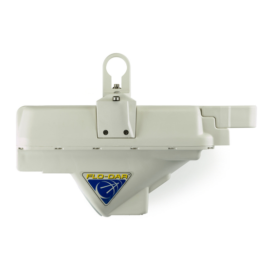
Hach FLO-DAR User Manual
Open channel non-contact radar sensor
with optional surcharge velocity sensor
Hide thumbs
Also See for FLO-DAR:
- Basic user manual (286 pages) ,
- User manual (45 pages) ,
- User manual (44 pages)
Table of Contents
Advertisement
Quick Links
Download this manual
See also:
User Manual
Rhein Tech Laboratories, Inc.
360 Herndon Parkway
Suite 1400
Herndon, VA 20170
http://www.rheintech.com
Ap p e n d ix K:
Ma n u a l
Please see the following pages.
Client:
Hach Company
Model:
FLO-DAR Sensor, 24GHz
Standards:
FCC 15.245, IC RSS-210
ID's:
VIC-FLODAR24/
6149A-FLODAR24
Report #:
2009165
Page 27 of 52
Advertisement
Table of Contents

Related Manuals for Hach FLO-DAR


Summary of Contents for Hach FLO-DAR
- Page 1 Rhein Tech Laboratories, Inc. Client: Hach Company 360 Herndon Parkway Model: FLO-DAR Sensor, 24GHz Suite 1400 Standards: FCC 15.245, IC RSS-210 Herndon, VA 20170 ID’s: VIC-FLODAR24/ http://www.rheintech.com 6149A-FLODAR24 Report #: 2009165 Ap p e n d ix K: Ma n u a l Please see the following pages.
- Page 2 DOC026.53.00786 FLO-DAR™ Open Channel Non-Contact Radar Sensor with Optional Surcharge Velocity Sensor USER MANUAL August 2009, Edition2 © HACH Company, 2008. All rights reserved. Printed in the U.S.A.
-
Page 4: Table Of Contents
3.2.2.2 Install the frame on the wall ..................19 3.2.2.3 Install the sensor on the frame................. 20 3.2.2.4 Align the sensor vertically—Flo-Dar without SVS ............ 21 3.2.2.5 Align the sensor vertically—Flo-Dar with SVS ............22 3.2.2.6 Align the sensor horizontally ..................23 3.2.2.7 Make a final alignment check................... - Page 5 Table of contents...
-
Page 6: Section 1 Specifications
Section 1 Specifications Specifications are subject to change without notice. Flo-Dar sensor Dimensions (without SVS) 17.5 cm W x 42.3 cm L x 29.7 cm D (6.9 in. x 16.65 in. x 11.7 in.) Weight 4.8 kg (10.5 lb) Enclosure... - Page 7 Specifications...
-
Page 8: Section 2 General Information
Section 2 General information 2.1 Safety information Please read this entire manual before unpacking, setting up, or operating this equipment. Pay attention to all danger and caution statements. Failure to do so could result in serious injury to the operator or damage to the equipment. To ensure that the protection provided by this equipment is not impaired, do not use or install this equipment in any manner other than that specified in this manual. -
Page 9: Confined Space Precautions
Important Note: The following information is provided to guide users of Flo-Dar and SVS Sensors on the dangers and risks associated with entry into confined spaces. On April 15, 1993, OSHA’s final ruling on CFR 1910.146, Permit Required Confined Spaces, became law. -
Page 10: Product Overview
General information 2.2 Product overview The Flo-Dar Sensor measures the flow velocity and liquid depth in open channels using radar and ultrasonic technology. The unit is designed to withstand submersion during surcharge conditions. The optional surcharge velocity sensor provides velocity measurements during surcharge conditions. - Page 11 The pipe diameter is used to convert the distance to water depth. The depth sensor on the Flo-Dar unit can measure distances up to 1.5 m (5 ft). For larger channels, an extended range sensor is available to measure up to 5.7 m (18.7 ft).
-
Page 12: Section 3 Installation
Flo-Dar Sensor can only be installed in non-hazardous environments. CAUTION: Radar RF Exposure Hazard Although the Flo-Dar microwave power level is very small (~15mW) and is well below government stated exposure limits for uncontrolled environments, users of this product should follow proper safety protocols for the handling of devices with radar frequency transmitters. - Page 13 Installation Figure 2 Instrument components Surcharge velocity sensor (SVS) (optional) 10 Clamp bolt, ¼–20 x 1 in. (8x) Flo-Dar sensor 11 Anchor nut, –16 (2x) Optional extended depth sensor 12 Anchor washer (2x) Bubble level 13 Anchor, x 2¼ in. (2x)
-
Page 14: Mechanical Installation
Installation 3.2 Mechanical installation 3.2.1 Site location guidelines For best accuracy, install the sensor where the flow is not turbulent. An ideal location is in a long, straight channel or pipe. Outfalls, vertical drops, baffles, curves or junctions cause the velocity profile to become distorted. Where there are outfalls, vertical drops, baffles, curves or junctions, install the sensor upstream or downstream as shown in Figure 3... - Page 15 Installation Figure 4 Sensor location near a curve, elbow or junction Acceptable upstream sensor location Distance downstream: 10 x pipe diameter Acceptable downstream sensor location Distance upstream: 5 x pipe diameter...
-
Page 16: Sensor Installation
Installation 3.2.2 Sensor installation Mount the Flo-Dar sensor above the open channel on the wall of the manhole. A pole is available for retrieval of the Flo-Dar sensor without entry into the manhole. For temporary installation, an optional Jack-bar is available (see... - Page 17 Installation Figure 6 Flo-Dar sensor with SVS dimensions Minimum clearance for cable...
-
Page 18: Assemble The Clamps On The Frame And Wall Bracket
Installation The dimensions of the standard frame for wall installation are shown in Figure Figure 7 Standard frame dimensions 22.8 in. with 2¼ in. spacer; 32.6 in. with 12 in. spacer 3.2.2.1 Assemble the clamps on the frame and wall bracket Install the clamps on the frame and wall mount bracket before installation on the wall. - Page 19 Installation 3. Position the other two clamp halves around the front end of the frame as shown in Figure Note: In most cases the front of the frame will point toward the wall as shown in Figure 8 (see also Figure 12 on page 23).
-
Page 20: Install The Frame On The Wall
(Figure 9). The wall brackets will be installed above and below this mark. • Flo-Dar without SVS—make sure that when the sensor is in the frame, the radar beam will not be blocked by the wall or channel (Figure 11). -
Page 21: Install The Sensor On The Frame
Installation Figure 9 Wall installation Distance from crown of pipe to top of frame Washer Anchor 3.2.2.3 Install the sensor on the frame The sensor fits in the frame in only one direction and locks in position when the bail on the sensor is turned (Figure 10). -
Page 22: Align The Sensor Vertically-Flo-Dar Without Svs
Bubble level Bail 3.2.2.4 Align the sensor vertically—Flo-Dar without SVS The sensor must be aligned vertically to make sure that the sensor is above the flow and that the radar beam will not be blocked by the wall or pipe (Figure 11). -
Page 23: Align The Sensor Vertically-Flo-Dar With Svs
Installation Figure 11 Vertical alignment of Flo-Dar sensor Spacer Distance from crown of pipe to top of frame 3.2.2.5 Align the sensor vertically—Flo-Dar with SVS The sensor must be aligned vertically to make sure that the sensor is above the flow under normal full flow conditions and that the SVS is activated under surcharge conditions. -
Page 24: Align The Sensor Horizontally
Installation 4. Tighten the clamp and measure the frame position again to make sure it is at the correct position. Figure 12 Vertical alignment of Flo-Dar sensor with SVS Spacer SVS sensor (optional) Distance from crown of pipe to top of frame 3.2.2.6 Align the sensor horizontally... -
Page 25: Make A Final Alignment Check
Installation 3.2.2.7 Make a final alignment check The correct vertical and horizontal alignment of the sensor is necessary for accurate measurements. 1. Measure the vertical alignment (section 3.2.2.4 on page 21 section 3.2.2.5 on page 22) and make adjustments if necessary. 2. - Page 26 Installation Figure 14 Extended frame dimensions 29.1 in. with 2¼ in. spacer; 38.8 in. with 12 in. spacer Figure 15 Vertical alignment with extended depth sensor Spacer...
-
Page 27: Measure The Sensor Offset
Installation 3.2.3 Measure the sensor offset The sensor offset is the distance from the top of the frame to the bottom of the pipe or channel. This distance will be entered into the software and is necessary for accurate flow calculations. If the extended depth sensor (section 3.2.2.8 on page 24) is installed on the wall without... -
Page 28: Measure The Pipe Diameter
CAUTION: Radar RF Exposure Hazard Although the Flo-Dar microwave power level is very small (~15mW) and is well below government stated exposure limits for uncontrolled environments, users of this product should follow proper safety protocols for the handling of devices with radar frequency transmitters. -
Page 29: Connection To The Logger Or Controller
Connect the cable from the Flo-Dar sensor to the logger or the controller: • Logger—connect the cable from the Flo-Dar sensor to the Flo-Dar connector on the logger. If the Flo-Dar sensor has the SVS component, connect the cable from the SVS component to the SVS connector on the logger. •... -
Page 30: Section 4 Operation
4. Open and run the flodar.exe file. An installation wizard will start. Follow the on-screen instructions to install the software. 4.2 Set up the logger Complete the steps to set up the Flo-Dar sensor for communication with the logger. Refer to the user manual for the logger for additional information. Procedure 1. - Page 31 Operation Figure 18 Site setup screen...
-
Page 32: Section 5 Maintenance
Inspect the cable connectors for any damage or corrosion and tighten all connectors in the system. The only parts of the Flo-Dar system that can be replaced by the user are the bail assembly, cable and desiccant. If the sensor becomes defective, it must be replaced as a complete unit. -
Page 33: Cable Replacement
DANGER Explosion hazard. Never attempt to wipe or clean the Flo-Dar or SVS sensor while in a hazardous location. Do not use abrasives or high-pressure hoses or washers to clean the sensors. Do not disturb the pressure port on the bottom of the sensor. -
Page 34: Section 6 Replacement Parts And Accessories
Cable assembly, 30 ft, connectors on both ends 131012601 Cable assembly, 60 ft, connectors on both ends 131012611 Cable assembly, 100 ft, connectors on both ends 131012602 Flo-Dar sensor 890004901 SVS Surcharge Velocity Sensor, replacement only 890006001 Wall mount assembly, standard frame (includes frame and hardware) 800016701... - Page 35 Replacement Parts and Accessories...
-
Page 36: Section 7 How To Order
1-301-874-5599 or send email to sales@marsh-mcbirney.com or 4-5599 or send visit www.marsh-mcbirney.com. sit www.marsh-mcbirney.co Information required Information required • • Hach account number (if available) • Hach account number Billing address • • Your name and phone number Your name and phone n •... - Page 37 How to order...
-
Page 38: Section 8 Repair Service
Section 8 Repair service Under normal operating conditions the Flo-Dar System should not need to be returned for repair or calibration. If the sensor or Flo-Logger/Flo-Station or both need to be returned to the factory for repair, do the following: 1. - Page 39 Repair service...
-
Page 40: Section 9 Limited Warranty
Section 9 Limited warranty Manufacturer warrants all products of its manufacture to be free from defects in workmanship and material under normal use and service. This warranty extends for a period of twelve (12) months after date of shipment, unless altered by mutual agreement between the purchaser and manufacturer prior to the shipment of the product. - Page 41 Limited warranty...
Need help?
Do you have a question about the FLO-DAR and is the answer not in the manual?
Questions and answers