Hach Flo-Dar User Manual
Intrinsically safe sensor, open channel non-contact radar sensor with optional surcharge velocity sensor
Hide thumbs
Also See for Flo-Dar:
- Basic user manual (286 pages) ,
- User manual (45 pages) ,
- User manual (36 pages)
Table of Contents
Advertisement
Quick Links
Download this manual
See also:
User Manual
Advertisement
Table of Contents

Related Manuals for Hach Flo-Dar


Summary of Contents for Hach Flo-Dar
- Page 1 DOC026.53.00817 Flo-Dar™ Intrinsically Safe Sensor Open Channel Non-Contact Radar Sensor with Optional Surcharge Velocity Sensor USER MANUAL 09/2015, Edition 3...
-
Page 3: Table Of Contents
3.3.2 Electrical installation in a hazardous location ..............11 3.3.2.1 Install the barrier ...................... 11 3.3.2.2 Wiring to the barrier....................13 3.3.2.3 Connection to the logger or controller ..............15 3.4 Approved Flo-Dar installation drawings ..................15 Section 4 Maintenance ........................19 4.1 Cleaning the instrument ......................20... - Page 4 Table of contents...
-
Page 5: Section 1 Specifications
Specifications are subject to change without notice. General cETLus Listed, ATEX EC-Type Certified Flo-Dar: II2G, Ex ib IIB T4 Gb, ITS10ATEX27065X, and Class I, Zone 1 AEx ib IIB T4 Gb and Class I, Zone 1 Ex ib IIB T4 Gb... - Page 6 Specifications...
-
Page 7: Section 2 General Information
Section 2 General information 2.1 Safety information Please read this entire manual before unpacking, setting up, or operating this equipment. Pay attention to all danger and caution statements. Failure to do so could result in serious injury to the operator or damage to the equipment. To ensure that the protection provided by this equipment is not impaired, do not use or install this equipment in any manner other than that specified in this manual. -
Page 8: Confined Space Precautions
Remarque importante : Les informations suivantes sont fournies dans le but d'informer les utilisateurs des capteurs Flo-Dar des dangers et des risques associés à l'accès aux espaces confinés. On April 15, 1993, OSHA’s final ruling on CFR 1910.146, Permit Required Confined Spaces, became law. -
Page 9: Product Overview
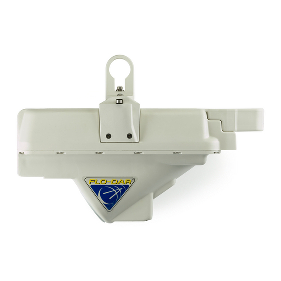
2.2 Product overview The Flo-Dar Intrinsically Safe Sensor measures the flow velocity and liquid depth in open channels using radar and ultrasonic technology. The unit is designed to withstand submersion during surcharge conditions. The optional surcharge velocity sensor provides velocity measurements during surcharge conditions. - Page 10 General information...
-
Page 11: Section 3 Installation
à des préjudices constituant un danger de mort et/ou des dégâts sur les installations. The Flo-Dar Intrinsically Safe Sensor is listed as intrinsically safe for Class 1, Zone 1, Group IIB Hazardous Locations. This means that the circuits within these sensors cannot produce a spark or thermal effect that could ignite a mixture of flammable or combustible gases when installed properly. -
Page 12: Sensor Installation
Mount the Flo-Dar sensor above the open channel on the wall of the manhole. For hazardous locations, a barrier must be installed outside of the hazardous area. To prevent damage to the enclosure, do not mount the Flo-Dar sensor in a location that receives direct sunlight. -
Page 13: Electrical Installation In A Hazardous Location
SVS component and the logger or controller. 3.3.2.1 Install the barrier A barrier must be installed when the Flo-Dar sensor is installed in a hazardous location as defined in section 3.1 on page 9. - Page 14 Installation Figure 2 Barrier dimensions Desiccant Connector for protective earth ground (PEG)
-
Page 15: Wiring To The Barrier
Procedure 1. Remove the four screws from the cover of the barrier. Remove the cover. 2. Insert the cable from the Flo-Dar sensor through the strain relief fitting on the side of the barrier with the hazardous area connection label (Figure 3 on page 14). - Page 16 Installation Figure 3 Barrier wiring Cable to logger or controller Cable from Flo-Dar or SVS sensor...
-
Page 17: Connection To The Logger Or Controller
Logger—connect the cable from the barrier to the connector on the logger. Make sure that the barrier that is connected to the Flo-Dar sensor is connected to the Flo-Dar connector on the logger. Make sure that the barrier that is connected to the optional SVS sensor is connected to the SVS connector on the logger. - Page 18 Installation Figure 5 Installation Control Drawing 1...
- Page 19 Installation Figure 6 Installation Control Drawing 2...
- Page 20 Installation Figure 7 Installation Control Drawing 3...
-
Page 21: Section 4 Maintenance
Flo-Dar Sensor User Manual. The Flo-Dar sensor contains no user serviceable or repairable components. If service is necessary, the Flo-Dar sensor must be sent to an authorized service center for repair or servicing. -
Page 22: Cleaning The Instrument
4.1 Cleaning the instrument DANGER Explosion hazard. Never attempt to wipe or clean the Flo-Dar or SVS sensor while in a hazardous location. Do not use abrasives or high-pressure hoses or washers to clean the sensors. Do not disturb the pressure port on the bottom of the sensor. - Page 23 Maintenance...
- Page 24 Tel. +49 (0) 2 11 52 88-320 SWITZERLAND Tel. (800) 368-2723 Fax +49 (0) 2 11 52 88-210 Tel. +41 22 594 6400 hachflowsales@hach.com info@de.hach.com Fax +41 22 594 6499 www.hachflow.com www.de.hach.com © Hach Company/Hach Lange GmbH, 2010–2011, 2015. All rights reserved. Printed in U.S.A.
Need help?
Do you have a question about the Flo-Dar and is the answer not in the manual?
Questions and answers