Table of Contents
Advertisement
Advertisement
Table of Contents

Subscribe to Our Youtube Channel
Related Manuals for Aastra TA7102i

Summary of Contents for Aastra TA7102i
- Page 1 TA7102i Hardware Installation Guide...
-
Page 2: Table Of Contents
Analog Line Interface (FXS) Audio Specifications DTMF Tone Detection DTMF Tone Generation Power Consumption 7.10 MTBF Value 7.11 Operating Environment 7.12 Dimensions and Weight Appendix D - Glossary ........................ 47 © 2014 Aastra Sweden | 153_1531 ANF 90114| A | 2014-01-24 A... - Page 3 TA7102i Hardware Installation Appendix E – List of Acronyms ....................50 © 2014 Aastra Sweden | 153_1531 ANF 90114| A | 2014-01-24 A...
- Page 4 No parts of this publication may be subject to alteration, modification or commercial use. Aastra will not be liable for any damages arising from use of an illegal modified or altered publication.
-
Page 5: About This Manual
Service Provider’s IP Telephony offering to residential or SME markets. Document Objectives The TA7102i Hardware Installation Guide provides technical information on how to physically install the TA7102i. It also describes the cabling required for the TA7102i device. The information included in this guide consists of: •... -
Page 6: Document Structure
“Appendix B - Cabling Describes the pin-to-pin connections for cables used Considerations” with the TA7102i. “Appendix C - Standard Lists the technical hardware information of the Hardware Information” TA7102i. © 2014 Aastra Sweden | 153_1531 ANF 90114| A | 2014-01-24 A... -
Page 7: Document Conventions
19. This Appendix describes the international agency compliance and safety information for the TA7102i. It also includes a translation of the safety warning listed in the previous section. Other Conventions The following are other conventions you will encounter in this manual. - Page 8 TA7102i Hardware Installation RFCs (Request for Comments), Internet-Drafts, or other standards. The TA7102i’s implementations are based on the standards, so it’s possible that some behavior differs from the official standards. For more information on and a list of RFCs and Internet-Drafts, refer to the IETF web site at http://www.ietf.org.
-
Page 9: Overview
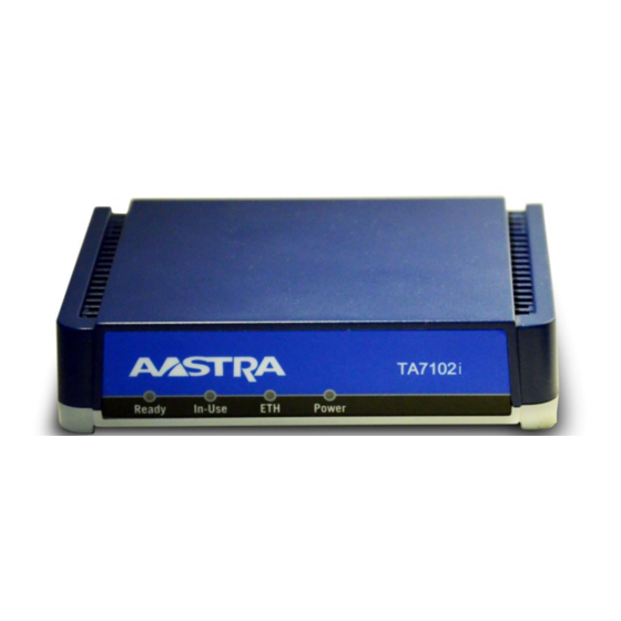
Overview This chapter describes the TA7102i connectors and indicators. Provider-specific profiles ensure that the TA7102i is a genuine plug and play solution. It offers a low total cost of ownership as it reduces installation and maintenance costs. Moreover, the TA7102i integrates features such as TLS, SRTP, and HTTPS designed to bring enhanced security for network management, SIP signaling and media transmission aspects. - Page 10 This section provides an overview of the front and rear panels of the TA7102i. Product Serial Number Location The serial number label for the TA7102i device is located on the bottom of the unit. Front Indicators and Connectors See “Indicators (LEDs)” for a description of the LED patterns the TA7102i may have and the states they represent.
- Page 11 TA7102i Hardware Installation Provides the state of the network connected to the WAN and LAN connectors. Power When lit, power is applied to the TA7102i. © 2014 Aastra Sweden | 153_1531 ANF 90114| A | 2014-01-24 A...
- Page 12 TA7102i Hardware Installation Rear Connectors The TA7102i has several connections that must be properly set. Figure 2 shows the rear panel of the TA7102i. Standards Supported -ITU-T I.430 Basic user-network interface - Layer 1 specification (section 9). Figure 2: TA7102i Rear Panel Connectors Table 3 describes the rear panel connections (from left to right).
- Page 13 (known) values. It can be used to reconfigure the unit. Warning: Read Section “RESET/DEFAULT Button” before attempting to reset the unit. Power External 12 Vdc power supply. connecto © 2014 Aastra Sweden | 153_1531 ANF 901 14| A | 2014-01-24 A...
-
Page 14: Connectors And Indicators Installation
(see section“Network Information”). Installation Checklist The installation checklist lists the tasks for installing the TA7102i. Print a copy of this checklist and mark the entries as you complete each task. Include the completed checklist in your site log. Figure 3: Installation Checklist... - Page 15 Initial configuration performed Initial operation verified Site Log Aastra recommends that you maintain a site log to record all actions relevant to the TA7102i, such as: • Installation: Print a copy of the installation checklist and insert it into the site log.
-
Page 16: Safety Recommendations
The following are safety recommendations and best practices to follow when working with the TA7102i. Maintaining Safety with Electricity Warning: Do not work on the TA7102i, connect or disconnect cables during periods of lightning activity. Warning: Disconnect all power before servicing the TA7102i. -
Page 17: Required Mounting Tools And Equipment
Install the TA7102i in a well-ventilated location where it will not be exposed to high temperature or humidity. Do not install the TA7102i in a location exposed to direct sunlight or near stoves or radiators. Excessive heat could damage the internal components. - Page 18 • Water or moisture that could enter the casing of the TA7102i. • The airflow is not restricted around the TA7102i or through the vents of the unit. The unit requires a minimum of 25 mm (1 in.) clearance. •...
- Page 19 6. Proceed to Hardware Installation. Free Standing Unit When installing the TA7102i on a desk or table, it should be located at least 20 cm from your monitor, computer casing or other peripherals, including speakers. Never put books or paper on the TA7102i.
- Page 20 Cleaning To clean the TA7102i, wipe with a soft dry cloth. Do not use volatile liquids such as gas and thinner that are harmful to the unit casing. For resistant markings, wet a cloth with a mild detergent, wring well and then wipe off. Use a dry cloth to dry the surface.
-
Page 21: Hardware Installation
This section describes how to set the connectors of the TA7102i. Warning: Do not connect the TA7102i directly to Telecommunication Systems. Caution: The TA7102i must be installed on a circuit equipped with a breaker so that you can easily power the unit off if required. - Page 22 TA7102i Hardware Installation Connect the power cord to the TA7102i. Do not yet connect the other end of the power cord to an electrical outlet. You are now ready to start the TA7102i. © 2014 Aastra Sweden | 153_1531 ANF 90114| A | 2014-01-24...
-
Page 23: Powering On The Ta7102I
Once the physical connection is complete and the TA7102i is powered up, you must first find out the IP address the TA7102i is using. The TA7102i's IP address can be set either dynamically or statically. The default behavior of the TA7102i is to try to obtain a dynamic IP address through a DHCP server. - Page 24 • To start the TA7102i with a dynamic IP address: 1. If you need to discover the IP address of the TA7102i, install and start your network packet sniffer. 2. Power on the TA7102i by connecting the other end of the power cord to an electrical outlet.
- Page 25 255.255.255.0. 3. Restart the computer. 4. Power on the TA7102i, by connecting the other end of the power cord to an electrical outlet. The electrical outlet must be installed near the TA7102i so that it is easily accessible. 5. Insert a small, unbent paper clip into the Reset / Default hole located at the rear of the TA7102i.
- Page 26 Current IP address of the TA7102i (static or DHCP). *#*1 MAC address of the TA7102i. Verifying the Installation There are a few ways to verify that the TA7102i is properly connected to the IP network and is working: • By contacting it with a SNMP browser •...
-
Page 27: Indicators (Leds)
TA7102i Hardware Installation These procedures assume that you know the IP address of the TA7102i you want to verify. If TA7102i does not respond, do the following: • Verify that the LAN and WAN cables are securely connected to the TA7102i and to the network connectors. - Page 28 No network address set Triggered when the unit cannot be Power LED: contacted because DHCP failed, PPP • blinking, 3 Hz, 50% failed, and no static interface is duty. configured. © 2014 Aastra Sweden | 153_1531 ANF 90114| A | 2014-01-24...
- Page 29 Ready LED: a firmware given by the Network • Rescue server. All other LEDs: • blinking to show a LED displacing light from left to right and right to left. © 2014 Aastra Sweden | 153_1531 ANF 90114| A | 2014-01-24...
-
Page 30: Reset/Default Button
The RESET/DEFAULT button allows you to: • Cancel an action that was started. • Revert to known factory settings if the TA7102i refuses to work properly for any reason or the connection to the network is lost. 3. Reconfigure a unit. At Run-Time The RESET/DEFAULT button can be used at run-time –... - Page 31 You can use the RESET/DEFAULT button at start-time – you power the unit off, and then depress the button until the LEDs stop blinking and remain ON. This applies the “Factory Reset” procedure (see Factory Reset). This feature reverts the TA7102i back to its default factory settings.
- Page 32 TA7102i Hardware Installation Partial Reset The Partial reset provides a way to contact the TA7102i in a known and static state while keeping most of the configuration unchanged. Following a partial reset, the TA7102i management interface is set to the Rescue interface. The default address for this interface is 192.168.0.1/24 and has its corresponding link-local IPv6...
- Page 33 The Factory reset creates a new configuration file with the default factory values. It should be performed with the TA7102i connected to a network with access to a DHCP server. If the unit cannot find a DHCP server, it sends requests indefinitely.
-
Page 34: Management Choices
TA7102i. While pressing the Reset / Default button, restart the unit. Do not depress before the LEDs stop blinking and are steadily ON. 3. Release the paper clip. The TA7102i restarts. This procedure resets all variables in the MIB modules to their default value. When the TA7102i has finished its provisioning sequence, it is ready to be used with a DHCP-provided IP address and MIB parameters. -
Page 35: Appendix A - Standard Compliance And Safety Information
Connect the equipment into an outlet on a circuit different from that to which the receiver is connected. • Consult the dealer or an experienced radio/TV technician for help Note: Any changes or modifications not expressly approved Aastra could void the user’s authority to operate the equipment. CE Marking DECLARATION OF CONFORMITY Please see www.aastra.com. -
Page 36: Translated Warning Definition
TA7102i Hardware Installation Translated Warning Definition The following information provides an explanation of the symbols which appear on the TA7102i and in the documentation for the product. Warning: Means danger. You are in a situation that could cause bodily injury. Before you work... -
Page 37: Safety Warnings
Public Switched Telephone Network (PSTN), to an off premise application, an out of plant application, any exposed plant application, or to any equipment other than the intended application, connection may result in a safety hazard, and/or defective operation and/or © 2014 Aastra Sweden | 153_1531 ANF 90114| A | 2014-01-24... -
Page 38: Safety Recommendations
Avoid using a telephone (other than a cordless type) during an electrical storm. There may be a remote risk of electric shock from lightning. • Do not use the telephone to report a gas leak in the vicinity of the leak. © 2014 Aastra Sweden | 153_1531 ANF 90114| A | 2014-01-24... -
Page 39: Appendix B - Cabling Considerations
Duplex), the type of cable to use depends on the other peer. For example, a straight cable is required to connect the TA7102i to a hub or a switch, while a crossover cable is required to connect the TA7102i to a PC. - Page 40 Pin 1 Pin 2 Pin 2 Pin 3 Pin 3 Pin 6 Pin 6 Pin Name and Function The following is the function of each pin in a RJ-45 cable. © 2014 Aastra Sweden | 153_1531 ANF 90114| A | 2014-01-24...
- Page 41 A crossover cable is sometimes called a null modem. The coloured wires at either end are put into different pin numbers, or crossed over. Figure 8: Crossover Connectivity 1- TX+ TX+ -1 2- TX- TX- -2 3- RC+ RC+ -3 6- RC- RC- -6 © 2014 Aastra Sweden | 153_1531 ANF 90114| A | 2014-01-24...
-
Page 42: Telephone) Cable
• EIA/TIA-IS 968 • CS-03 Issue 8, Part III requirements. Warning: The RJ-11 cable should comply with UL 1863 and CSA C22.2 No 233 standards. © 2014 Aastra Sweden | 153_1531 ANF 90114| A | 2014-01-24... -
Page 43: Appendix - C Standard Hardware Information
Industry Standard Protocols The TA7102i has been designed to support all major industry standards used today, as well as those that will eventually be implemented at a later date. Because of this specific design characteristic, the TA7102i can be integrated with existing telephone, fax and data equipment such as PCs and routers. -
Page 44: Hardware Features
10/100 BaseT Ethernet Data Link Ethernet Network IP (Internet Protocol) Transport TCP / UDP Protocols Group 3 Fax Clear channel (G.711), G.726 or T.38 Real Time Fax Over IP protocol Stack © 2014 Aastra Sweden | 153_1531 ANF 90114| A | 2014-01-24... -
Page 45: Analog Line Interface (Fxs)
Software-adjustable dynamic and static jitter buffer protection. • Programmable by country: Call progress tone generation including dial tone, busy tone, ringback and error tones. • DSP-based echo control device. • Silence detection/suppression level software adjustable. © 2014 Aastra Sweden | 153_1531 ANF 90114| A | 2014-01-24... -
Page 46: Dtmf Tone Detection
(mA) n (W) 120Vac / All ports off 60Hz hook 240Vac / All ports off TA7102i 50Hz hook 12Vdc All ports off hook 12Vdc All ports ringing into 4REN © 2014 Aastra Sweden | 153_1531 ANF 90114| A | 2014-01-24... -
Page 47: Mtbf Value
MTBF Value 7.10 The Mean Time Before Failure (MTBF) value of the TA7102i models is 750,000 hours. These values are at 25 degrees Celsius ambient temperature. It has been defined using RelCalc v5.0, Bellcore method (LimitedStress - Method I, Case 3), Desktop unit excluding the power adaptor. -
Page 48: Appendix D - Glossary
Light Emitting Diode (LED) A semiconductor diode that emits light when a current is passed through it. Local Area Network (LAN) © 2014 Aastra Sweden | 153_1531 ANF 90114| A | 2014-01-24... - Page 49 A protocol for transporting call setup, routing, authentication, and other feature messages to endpoints within the IP domain, whether those messages originate from outside the IP cloud over SCN resources or within the cloud. © 2014 Aastra Sweden | 153_1531 ANF 90114| A | 2014-01-24...
- Page 50 Wide Area Network (WAN) A large (geographically dispersed) network, usually constructed with serial lines, that covers a large geographic area. A WAN connects LANs using transmission lines provided by a common carrier. © 2014 Aastra Sweden | 153_1531 ANF 90114| A | 2014-01-24...
- Page 51 Public Switched Telephone Network Request for Comment Switched Circuit Network Session Initiation Protocol Small and Medium-sized Enterprise Twisted-Pair Ethernet Unshielded Twisted pair VoIP Voice over Internet Protocol Wide Area Network © 2014 Aastra Sweden | 153_1531 ANF 90114| A | 2014-01-24...
- Page 52 NOTICE The information in this document is subject to change without notice. AASTRA MAKES NO WARRANTY OF ANY KIND WITH REGARD TO THIS MATERIAL, INCLUDING, BUT NOT LIMITED TO, THE IMPLIED WARRANTIES OF MERCHANTABILITY AND FITNESS FOR A PARTICULAR PURPOSE. AASTRA shall not be liable for errors contained herein, neither for incidental nor for consequential damages in connection with the furnishing, performance, or use of these materials.
Need help?
Do you have a question about the TA7102i and is the answer not in the manual?
Questions and answers