Table of Contents
Advertisement
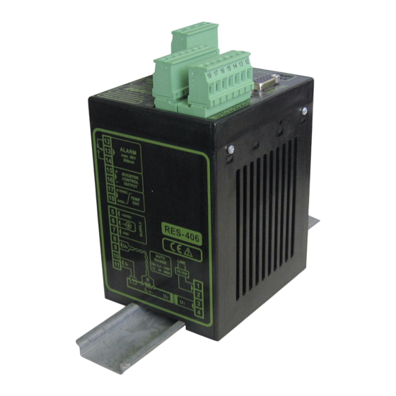
RESISTRON
RES-406
Operating
instructions
Important features
•
Microprocessor technology
•
Complete control via PROFIBUS-DP interface
•
Automatic zero calibration (AUTOCAL)
•
Automatic optimization (AUTOTUNE)
•
Automatic configuration of the secondary voltage and current ranges
(AUTORANGE, as of February 2006)
•
Automatic phase angle compensation (AUTOCOMP, as of February 2006)
•
Automatic frequency adjustment
•
Large current and voltage range
•
Booster connection as standard
•
0...10VDC analog output for ACTUAL temperature
•
Alarm function with fault diagnosis
•
Heatsealing band alloy and temperature range selectable
Industrie-Elektronik GmbH
Gansäcker 21
D-74321-Bietigheim-Bissingen (Germany)
GB
Tel: +49/(0)7142/7776-0
Fax: +49/(0)7142/7776-19
E-Mail:
info@ropex.de
Internet:
www.ropex.de
Data subject to change
Advertisement
Table of Contents

Related Manuals for Ropex RESISTRON RES-406


Summary of Contents for Ropex RESISTRON RES-406
- Page 1 Booster connection as standard • 0…10VDC analog output for ACTUAL temperature • Alarm function with fault diagnosis • Heatsealing band alloy and temperature range selectable Industrie-Elektronik GmbH Tel: +49/(0)7142/7776-0 E-Mail: info@ropex.de Gansäcker 21 Fax: +49/(0)7142/7776-19 Internet: www.ropex.de D-74321-Bietigheim-Bissingen (Germany) Data subject to change...
-
Page 2: Table Of Contents
Contents Safety and warning notes ....3 Startup and operation ....16 Use . -
Page 3: Safety And Warning Notes
The resistance of the heatsealing band which is used must have a positive minimum Only the original ROPEX PEX-W2 or PEX-W3 temperature coefficient in order to guarantee current transformer may be used. Other trouble-free... -
Page 4: Line Filter
DIN EN 61010-1 Safety provisions for electrical (VDE 0411-1) measuring, control and laboratory The use of an original ROPEX line filter is mandatory in devices (low voltage directive). order to comply with the standards and provisions Overvoltage category III, pollution mentioned in section 1.7 "Standards / CE marking"... -
Page 5: Principle Of Operation
Principle of operation The use of RESISTRON temperature controllers • Increased machine capacity results in: • Extended life of the heatsealing bands and teflon coatings • Repeatable quality of the heatseals under any conditions • Simple operation and control of the sealing process Principle of operation The resistance of the heatsealing band, which is transformer. -
Page 6: Description Of The Controller
Description of the controller Description of the controller microprocessor technology endows interface can be used to control all the controller RESISTRON temperature controller RES-406 with functions and interrogate controller information. previously unattainable capabilities: The ACTUAL temperature of the heatsealing band is supplied to the PROFIBUS interface and to an analog •... -
Page 7: Modifications (Mods)
Designed according to VDE 0570/EN 61558 with a one section bobbin. Optimized for impulse operation with RESISTRON temperature controllers. Specified according to the heatsealing application ( ROPEX Application Report). Communication interface CI-USB-1 Interface for connecting a RESISTRON temperature controller with diagnostic inter- face (DIAG) to the PC (USB port). -
Page 8: Technical Data
The temperature range and temperature coefficient settings can also be specified range by means of the ROPEX visualization software ( section 10.11 "Diagnostic interface/visualization software (as of February 2006)" on page 39) in addition to the rotary coding switch (see below): Temperature range: 200°C, 300°C, 400°C or 500°C... - Page 9 Technical data Analog output 0…10V DC, Imax = 5mA (actual value) Equivalent to 0…300°C or 0…500°C Terminals 17+18 Accuracy: ±1% add. 50mV Alarm relay = 50V (DC/AC), I = 0.2A, changeover contact, potential-free Terminals 12, 13, 14 Maximum load = 5A (duty cycle = 100%) (primary current of = 25A (duty cycle = 20%) impulse...
-
Page 10: Dimensions
12, section 8.6 "Wiring diagram (standard)" on page 14 Installation procedure and the ROPEX Application Report. The information provided in section 8.2 "Installation steps" on Proceed as follows to install the RESISTRON page 11 must also be heeded. -
Page 11: Installation Steps
Installation Installation steps Use heatseal bands with suitable temperature coefficient Heatseal element push-on with coppered ends connectors Heatsealing band R= f (T) No additional Connect U measuring resistance wires directly to in secondary Note heatsealing band ends circuit number Sufficient wire of turns Twisted cross-section... -
Page 12: Power Supply
Use transformers with a one section bobbin. The power, duty cycle and voltage values must be SEC. determined individually according to the application ( ROPEX Application Report and "Accessories" leaflet for impulse transformers). Wiring The wire cross-sections depend on the application (... -
Page 13: Line Filter
CE mark. The wiring instructions contained in section 8.3 "Power ROPEX line filters are specially optimized for use in supply" on page 12 must be observed. RESISTRON control loops. Providing that they are... -
Page 14: Wiring Diagram (Standard)
Installation Wiring diagram (standard) PROFIBUS-PLUG Line filter LF-xx480 SUB-D / 9-POLE RES-406 LINE Shield (GND pwr. supply) M24 PROFIBUS DGND controller electrically (+5V) VP isolated (+24V pwr. supply) P24 prim. Impulse transformer +24VDC sec. POWER SUPPLY Heat- sealing band twisted ALARM OUTPUT max. -
Page 15: Wiring Diagram With Booster Connection
Installation Wiring diagram with booster connection PROFIBUS-PLUG Line filter LF-xx480 SUB-D / 9-POLE RES-406 LINE Shield Booster (GND pwr. supply) M24 PROFIBUS DGND controller electrically (+5V) VP isolated (+24V pwr. supply) P24 prim. Impulse transformer +24VDC sec. POWER SUPPLY Heat- sealing band twisted... -
Page 16: Startup And Operation
The secondary voltage and current ranges are You can find the exact configuration of the automatically configured by the automatic calibration DIP switches in the ROPEX Application function (AUTOCAL). The voltage is configured in the Report calculated for your particular application. - Page 17 If the switch is set to "9" (as of February 2006), more available on controllers manufactured as of temperature ranges and alloys can be selected by October 2003. means of the ROPEX visualization software ( see section 10.11 "Diagnostic interface/visualization The setting of the rotary coding switch for the software (as of February 2006)"...
-
Page 18: Replacing And "Burning In" The Heatsealing Band
TCR. Too low a TCR leads to February 2006), the behavior of the alarm output can oscillation or uncontrolled heating. be configured in more detail by means of the ROPEX When heatsealing bands with a higher TCR are used, visualization software (... -
Page 19: Startup Procedure
One very important design feature is the copper or January 2006, the settings of the DIP switches on silver-plating of the heatsealing band ends. Cold ends the controller are indicated in the ROPEX allow the temperature to be controlled accurately and Application Report and depend on the heatsealing increase the life of the teflon coating and the band that is used. - Page 20 ACTION case the controller configuration is incorrect ( section 9.2 "Controller configuration" on page 16 Short pulses Go to 10 and ROPEX Application Report). Repeat the every 1.2s calibration after the controller has been configured correctly. BLINKS fast Go to 10 11.
-
Page 21: Controller Functions
AUTOCAL Remains lit for duration of RESISTRON (yellow LED) AUTOCAL process. RES- 406 Temperature controller ROPEX 24V SUPPLY Lit if external 24VDC power (green LED) supply is present. Tel:+49(0)7142-7776-0 BUS PWR OK Lit if internal 5VDC power (green LED) - Page 22 Yellow LED, lit during heating phase. RESISTRON Red LED, lights up or blinks to indicate alarm. μP-Controller ROPEX Green LED, remains lit as long as PROFIBUS data is beeing exchanged with master. INDUSTRIE - ELEKTRONIK In addition to the functions shown in the diagram by the LEDs.
-
Page 23: Profibus Communication „Up To Jan. 2006"/"As Of Feb. 2006
English (.GSD or .GSE) on a diskette. They can also be tion is always possible on these controllers as long as requested by E-Mail (support@ropex.de) or they can the 24VDC power supply is present, i.e. switching off be downloaded from our Homepage (www.ropex.de). -
Page 24: Profibus Protocol
Controller functions 10.4 PROFIBUS protocol and the control functions, to enable it to be decoded more easily by the PROFIBUS master. The PROFIBUS protocol can be configured either as Bits 0…7 form the low byte and bits 8…15 the "compact" (16bits for input data and 16bits for output high byte ("INTEL format"). - Page 25 Controller functions 10.4.3 "Extended" protocol with 4-Bit error code The extended protocol transfers 2x16bits. The 2x16- bit input data contains the set point in word and the control functions in word : Spare Set point / AC temperature Name: Bit no.: ...
-
Page 26: Input Data
Controller functions The 2x16-bit output data contains the actual value in word and the error code and status information in word : Actual value (signed) Name: Bit no.: Error code Status information Name: Bit no.: 10.5 Input data The AUTOCAL request ("AC"... - Page 27 Controller functions 4. If the "RESET" bit ("RS" bit = 1) is activated, the No AUTOCAL or START requests are accepted as AUTOCAL function is not executed. long as the "RS" bit is set. From then on, only fault nos. 5 and 7 (As of February 2006: 201…203, 901, 913) are 5.
-
Page 28: Output Data
Controller functions In contrast with the "RS" bit (RESET), the "MP" bit does mode is exited ("ST" bit = 0) or an alarm is signaled not reset any error message when it is set. The ("AL" bit = 1), this status bit is reset again. controller is activated again as soon as the bit is reset, 10.6.5 Temperature OK (TO) in other words there is no initialization phase. - Page 29 In the extended protocol, the error code appears in the second word at bit positions 8…11 (error code ROPEX visualization software. As of software revision 103 the configuration for the „TO“ bit is set in the format = 4-bit) or 6…15 (error code format = 10-bit) PROFIBUS parameter data (or the DPV1 protocoll (...
-
Page 30: Parameter Data
Controller functions In addition to the error codes, the PROFIBUS diagno- stics function also sends error messages to the fault Possible PROFIBUS master. The error messages correspon- Function value values ding to each error code are already stored in the device master file (GSD), so that they automatically appear in plain text on the PROFIBUS master whenever the Measuring impulse... - Page 31 780ppm (values 1 and 5) are only available on fault Possible controllers manufactured as of October 2003. Function value values The setting „ROPEX visualization software“ (value 9) is available on controllers manufac- „TO“ bit active off, tured as of March 2007 and supplied with GSD (Temperatur OK) active if Version v2.0.
-
Page 32: Dpv1 Protocol Extension
I measuring If you want to keep the old extended device diagnostics signals for special heatsealing applications ( ROPEX (e.g. for reasons of software compatibility), you must Application Report). The "AUTOCOMP" function is use a GSD version previous to v2.0. The DPV1 functio- provided for this purpose. - Page 33 Controller functions 2. „on“ AUTOCAL It is executed whenever the "AUTOCAL" function ( section 10.13 "Error messages" on page 40) is „AC“ run twice in quick succession. The interval between the end of the first "AUTOCAL" function and the start of the second "AUTOCAL"...
- Page 34 (304) is indicated and the alarm relay is switched temperature on the actual value output and the data ( section 10.13 "Error messages" on page 40). record in the graphics window of the ROPEX visua- lization software is not affected. Page 34...
-
Page 35: (As Of Gsd Version V2.0)
Controller functions The various hold modes are shown below: The "Holde mode" function must be activated by means of the PROFIBUS parameter data ( section 10.7 "Parameter data" on page 30) or „ST“ bit the DPV1 protocol extension ( section 10.8 "DPV1 protocol extension... - Page 36 Controller functions 10.8.3 DPV1 parameter data be altered on the PLC control unit during the validation process. The basic controller settings and functions can be set This acyclic service supports both reading and writing with the parameter data in the device master file (GSD of the controller parameters.
- Page 37 Controller functions Slot Index Parameter Value range Temperatur range 0: 200°C 1: 300°C 2: 400°C 3: 500°C Maximum temperature [°C] 200…500 (300) Temperature diagnosis 0: deactivated 1: activated Temperature diagnosis delay time 0…99 (0) [0.1s steps] Heatup timeout [0.1s steps] 0…999 (0) AUTOCOMP 0: off...
-
Page 38: Temperature Indication
An indicating instrument can be connected to this output in order to visualize the temperature of the heatsealing band. The characteristics of the ROPEX ATR-x temperature meter (size, scaling, dynamic response) are ideally suited to this application and this instrument should therefore always be used (... -
Page 39: 10.10 Booster Connection
The same applies if mutual interference damage to the controller. occurs between several neighboring control loops. The ROPEX visualization software is described in a This output is not potential-free and might separate document. have the potential of the secondary voltage of the impulse transformer. -
Page 40: 10.13 Error Messages
211, 302, 303), the signal at the analog output jumps the ROPEX visualization software ( section 10.11 back and forth at 1Hz between the voltage value which "Diagnostic interface/visualization software (as of... - Page 41 Controller functions RES-406 Page 41...
- Page 42 Controller functions Page 42 RES-406...
- Page 43 Controller functions RES-406 Page 43...
- Page 44 Controller functions Page 44 RES-406...
-
Page 45: 10.14 Fault Areas And Causes
Controller functions 10.14 Fault areas and causes Temperature controller HARDWARE The table below explains the possible fault causes. Fault area Explanation Possible causes Load circuit interrupted after U - Wire break, heatsealing band break - Contact to heatsealing band is defective pickoff point ... -
Page 46: Factory Settings
Factory settings Fault area Explanation Possible causes - Up to Jan. 2006: DIP switches 4 + 5 configured incorrectly range) signal incorrect - As of Feb. 2006: I outside permissible range from 30…500A Turns through PEX-W2/-W3 - Check number of turns (two or more turns required for current transformer incorrect currents <... -
Page 47: Maintenance
Maintenance Rotary coding Station address = 01 switches x 10 station address Top of housing Automatic phase AUTOCOMP: off angle compensation (AUTOCOMP) Temperature Temperature diagnosis: deactivated diagnosis Heatup timeout Heatup timeout: deactivated [X] As of February 2006 and GSD Version v2.0: Setting by means of the PROFIBUS parameter data or the DPV1 protocol extension. -
Page 48: How To Order
Line filter LF- . . 480 06: Continuous current 6A, 480VAC, Art. No. 885500 35: Continuous current 35A, 480VAC, Art. No. 885506 Impulse transformer See ROPEX Application Report for design and ordering information Communiction interface CI-USB-1 Art. No. 885650 Temp. meter ATR- . -
Page 49: Index
Index Index Nummern Error messages Extended controller diagnosis 24VDC-Supply voltage External switching amplifier "AA" bit Factory settings "AC" bit Fault areas Actual value Fault diagnosis Actual value output "AG" bit "AL" bit Alarm Alarm output Alarm relay Alloy Heatsealing band type Ambient temperature Heatup timeout Analog temperature meter... - Page 50 Index Compact, 10-Bit error code Compact, 4-Bit error code Extended, 10-Bit error code "TE" bit Extended, 4-Bit error code Temperature coefficient Temperature control Temperature diagnosis Temperature indication "RA" bit Temperature meter Replacing the heatsealing band Temperature OK Reset Temperature range "RS"...
Need help?
Do you have a question about the RESISTRON RES-406 and is the answer not in the manual?
Questions and answers