Table of Contents

Related Manuals for Cypress CapSense Express CY3280-MBR


Summary of Contents for Cypress CapSense Express CY3280-MBR
- Page 1 ® CY3280-MBR CapSense Express™ with SmartSense™ Auto-Tuning Kit Guide Doc. # 001-64772 Rev. ** Cypress Semiconductor 198 Champion Court San Jose, CA 95134-1709 Phone (USA): 800.858.1810 Phone (Intnl): 408.943.2600 http://www.cypress.com...
- Page 2 Cypress Source Code and derivative works for the sole purpose of creating custom soft- ware and or firmware in support of licensee product to be used only in conjunction with a Cypress integrated circuit as speci- fied in the applicable agreement.
-
Page 3: Table Of Contents
Contents 1. Introduction Kit Contents .........................5 Installation........................5 Features of CY3280-MBR Kit Board................5 Factory Default Configuration ..................5 Document Revision History ..................6 Documentation Conventions ..................6 2. Kit Operation Power Supply.......................8 System Block Diagram and Operation.................8 Controller Pin Assignment Details ................9 Connector Details ......................10 2.4.1 SmartSense Evaluation Header (Connector J5) ..........10 2.4.2 Expansion Connector One (Connector J1) ............10 2.4.3 Expansion Connector Two (Connector J2) ............11... - Page 4 Contents 3.7.1 Test CapSense Buttons with Sleep Feature Disabled ........20 3.7.2 Enable Sleep Feature ..................20 3.7.3 Test CapSense Buttons with Sleep Feature Enabled ........21 ARST Feature......................21 3.8.1 Enable ARST Feature..................21 3.8.2 Test CapSense Buttons with ARST Feature Enabled........22 FMEA Features ......................
-
Page 5: Introduction
Tuning Kit. The kit is designed to showcase the abilities of configurable capacitive sensing controller CY8CMBR2044. This controller is equipped with SmartSense, which allows engineers to go from prototyping to mass production without re-tuning for manufacturing variations in PCB and/or overlay material properties. For more information, visit http://www.cypress.com/?id=2014. Kit Contents CY3280-MBR Kit ■... -
Page 6: Document Revision History
Introduction Document Revision History Table 1-1. Revision History PDF Creation Origin of Revision Description of Change Date Change 11/25/10 New kit guide. Documentation Conventions Table 1-2. Document Conventions for Guides Convention Usage Displays file locations, user entered text, and source code: Courier New C:\ ...cd\icc\ Displays file names and reference documentation:... -
Page 7: Kit Operation
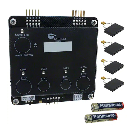
Kit Operation CY3280-MBR kit is designed to demonstrate four CapSense buttons and a CapSense based power button. Figure 2-1 illustrates these buttons: demonstration buttons (BTN0 to BTN3) and a CapSense power button (POWER BUTTON). The kit is powered from two AAA on-board batteries, which are placed below the kit in the battery holder. -
Page 8: Power Supply
Kit Operation Power Supply CY3280-MBR kit can be powered from two different power sources: external power supply and on- board battery power. External power supply can be provided from two connectors: J5 and J2. External power supplied through J2 is gated by the CapSense based power button; however, exter- nal power supplied through J5 is not gated. -
Page 9: Controller Pin Assignment Details
Kit Operation The kit can be powered from three sources. This includes power from on-board battery and external power through the J2 connector. A protection circuit is provided to prevent damage if both these sources are connected at the same time. The protection circuit allows only one power supply to be active at a time. -
Page 10: Connector Details
Kit Operation Connector Details 2.4.1 SmartSense Evaluation Header (Connector J5) Various signals are connected to the J5 connector, as shown in the following table. For more infor- mation on each signal, see the schematics of the CY3280-MBR kit. VDD and GND are connected to pin #1 and pin #2 on this connector such that external power supply can be connected to kit, if required. -
Page 11: Expansion Connector Two (Connector J2)
Kit Operation 2.4.3 Expansion Connector Two (Connector J2) Using the VDD and GND signals available in J2 connector, the kit can be powered from external power supply. Note that this power supply is gated through CapSense based power button circuitry. CapSense controller receives 200 mV less than what is applied to connector due to the drop out across the power button switch circuitry. -
Page 12: Default Configuration Of Kit
Kit Operation 2.5.2 Default Configuration of Kit Ensure SW1 is in Both Off position and SW2 is in Sleep Off position. Turn the 'Delay' and 'Sleep' potentiometers to extreme right to disable 'Delay Off' and sleep features of CapSense controller. Figure 2-4. -
Page 13: Kit Features
Kit Features This section demonstrates the main features of CY8CMBR2044 CapSense controller using the CY3280-MBR kit. Features of CY8CMBR2044 CapSense Controller CY8CMBR2044 has the following features: SmartSense ■ Toggle ■ Flanking sensor suppression (FSS) ■ Delay off ■ ScanRate/Sleep ■ ARST ■... -
Page 14: Toggle Feature
Kit Features Figure 3-1. External Capacitor Connected to J5 Connect capacitors of different values (22 pF and 33 pF). Ensure that power is toggled after placing a new capacitor. Button BTN2 continues to work. Now connect the 68-pF capacitor; BTN2 stops working. -
Page 15: Enable Toggle Feature
Kit Features 3.3.2 Enable Toggle Feature Ensure the position of SW1 is changed to Toggle On to enable the Toggle feature, see Figure 3-3. Touch the power button once to turn off the power; the power LED is turned off. Again press the power button to turn on the power. -
Page 16: Flanking Sensor Suppression (Fss) Feature
Kit Features Flanking Sensor Suppression (FSS) Feature The following steps demonstrate the FSS feature of CY8CMBR2044 CapSense controller using CY3280-MBR kit. Before proceeding, power the kit in default mode using the procedure provided in the section 2.5 Power the Kit on page 3.4.1 Test CapSense Buttons with FSS Feature Disabled Touch more than one CapSense buttons simultaneously;... -
Page 17: Toggle And Fss Features Combined
Kit Features Figure 3-7. FSS Feature Test Sequence 1. Touch two buttons; LED of 2. Release activated button, 3. Without releasing button, button pressed first turns on activated LED turns off and touch any button, no other the other LED turns on LED turns on Toggle and FSS Features Combined The following steps demonstrate the FSS and Toggle features of CY8CMBR2044 CapSense control-... -
Page 18: Test Capsense Buttons With Fss And Toggle Feature Enabled
Kit Features Figure 3-9. Switch Position for Toggle and FSS Features 3.5.3 Test CapSense Buttons with FSS and TOGGLE Feature Enabled Touch more than one CapSense button; only one LED is turned on. When the same button is released, the LED remains in ON state. Successive activation of button sensor makes the respective output toggle between the ON and OFF states. -
Page 19: Enable Delay Off Feature
Kit Features Figure 3-11. Kit with Delay Off Feature Disabled 1. Touch a button: LED turns on 2. Release button; LED turns off immediately 3.6.2 Enable Delay Off Feature The Delay Off pin is connected to a potentiometer and helps to change the resistor value to all sup- ported values. -
Page 20: Scanrate/Sleep Feature
Kit Features The time delay at which the LED is turned off automatically after the release of the respective button can be controlled using the potentiometer. Note that turning the potentiometer halfway make the LED turn off automatically within half the time of the first experiment. Refer the CY8CMBR2044 data sheet for more details. -
Page 21: Test Capsense Buttons With Sleep Feature Enabled
Kit Features 3.7.3 Test CapSense Buttons with Sleep Feature Enabled Touch any CapSense button; the respective LED turns on. When the finger is released, the LED turns off. There is no visible difference, but the CY8CMBR2044 CapSense controller is now working at lower average power. -
Page 22: Test Capsense Buttons With Arst Feature Enabled
Kit Features 3.8.2 Test CapSense Buttons with ARST Feature Enabled Touch any CapSense button; the respective LED turns on. Do not release the button; keep the finger pressed for more than 20 seconds. Notice that the LED turns off automatically after 20 seconds. Release the buttons and touch the same buttons again, it works as usual. -
Page 23: Test Fmea Feature - Capsense Button To Button Short
Kit Features Figure 3-19. BTN1 Sensor Shorted to Ground 3.9.3 Test FMEA Feature - CapSense Button to Button Short Follow these steps: 1. Press the power button to turn off the kit. 2. Connect a wire between pin# 4 and pin# 5 of connector J5. This shorts BTN1 and BTN2 sensors. 3. - Page 24 Kit Features CY3280-MBR CapSense Express with SmartSense Auto-Tuning Kit Guide, Doc. # 001-64772 Rev. **...
-
Page 25: Appendix
Appendix Board Schematics VD D _D ev R 21 22 Oh ms D E L AY P OT1 XR ES R 22 ZE R O Delay POT C S1 C S2 SLE EP _C N T R 23 ZE R O SLEE P 5 H EA D ER SW 2... - Page 26 V DD_Ext MBR0520L VDD_SW D NP M BR0520L VDD_B AT VO UT 330 ohm VDD_Dev ZERO M BR0520L V DD_SW GN D GND1 0.1 uFd Battery Clip AA A CO MN P WR_O N_INV 10 uFd 16v ZE RO LED Red 10 uFd 16v M IC94090 SC-70-6 Battery Clip AA A...
-
Page 27: Board Layouts
Board Layouts A.2.1 PDC-09587 Top CY3280-MBR CapSense Express with SmartSense Auto-Tuning Kit Guide, Doc. # 001-64772 Rev. **... - Page 28 A.2.2 PDC-09587 Bottom CY3280-MBR CapSense Express with SmartSense Auto-Tuning Kit Guide, Doc. # 001-64772 Rev. **...
-
Page 29: Bill Of Materials
Bill of Materials Item Qty Reference Value Description Manufacturer Mfr Part Number Cypress PDC-09587 Rev04 GRM2165C1H222 C1,C4 2200 pFd CAP CER 2200PF 50V 5% C0G 0805 Murata Electronics JA01D C0603C104K8RA C2,C5,C8,C9 0.1 uFd CAP .10UF 10V CERAMIC X7R 0603 Kemet CAP CERAMIC 10.0UF 16V X5R... -
Page 30: Frequently Asked Questions
Frequently Asked Questions This section provides solutions for errors that you may encounter when working with the CY3280- MBR kit. Q. Power LED does not turn when power button is pressed A. This can be due to the following reasons: The kit is not powered from any of the power sources. - Page 31 Q. Additional overlay sometimes create false triggers A. When an overlay is placed on the top of the button, capacitance may be increased and this is interpreted as finger signal. Every time overlay is changed, CapSense controller should be reset using XRES or power should be toggled.
- Page 32 CY3280-MBR CapSense Express with SmartSense Auto-Tuning Kit Guide, Doc. # 001-64772 Rev. **...
Need help?
Do you have a question about the CapSense Express CY3280-MBR and is the answer not in the manual?
Questions and answers