
Related Manuals for Cypress CY4609


Summary of Contents for Cypress CY4609
- Page 1 CY4609, CY4603, and CY4613 HX3 Kits User Guide Doc. #: 001-91203 Rev. *D Cypress Semiconductor 198 Champion Court San Jose, CA 95134-1709 Phone (USA): +1.800.858.1810 Phone (Intnl): +1.408.943.2600 http://www.cypress.com...
- Page 2 Cypress Source Code and derivative works for the sole purpose of creating custom soft- ware and or firmware in support of licensee product to be used only in conjunction with a Cypress integrated circuit as speci- fied in the applicable agreement.
-
Page 3: Table Of Contents
Abbreviations ......................12 2. Software Installation Install Software ......................13 Install Hardware......................15 Uninstall Software......................15 3. Kit Operation Overview of CY4609 RDK ..................17 3.1.1 CY4609 Board Interfaces................17 3.1.2 Jumper Settings .....................18 Overview of CY4603 DVK ..................19 3.2.1 CY4603 Board Interfaces................19 3.2.2 Jumper Settings .....................20 Overview of CY4613 DVK ..................21... - Page 4 4.3.5 Restoring CY4613 DVK to factory default firmware........56 4.3.6 Uninstall the CYUSBHX3 Vendor Driver............57 5. Hardware CY4609 RDK Hardware Design ................59 5.1.1 Board Details ....................59 5.1.2 Theory of Operation ..................60 5.1.3 Functional Description ................... 61 CY4603 DVK Hardware Design ................
-
Page 5: Safety Information
If such interference is detected, suitable mitigating measures should be taken. The CY4603, CY4609, and CY4613 kits as shipped from the factory have been verified to meet with the requirements of CE as a Class A product. - Page 6 Handling Boards CY4603, CY4609, and CY4613 boards are sensitive to ESD. Hold the board only by its edges. After removing the board from its box, place it on a grounded, static-free surface. Use a conductive foam pad if available.
-
Page 7: Introduction
Introduction Thank you for your interest in the CY4609, CY4603, and CY4613 HX3 kits. HX3 is a family of USB 3.0 hub controller parts compliant to USB 3.0 specification revision 1.0. These parts support Low-Speed (LS), Full-Speed (FS), Hi-Speed (HS), and SuperSpeed (SS) peripherals. -
Page 8: Kit Contents
ACA-Dock a. Shared Link is a Cypress-proprietary feature that enables a USB 3.0 port to be split into an embedded SS port and a standard USB 2.0 port. b. Battery Charging is supported on standard USB 3.0 and Shared Link USB 2.0 ports only. - Page 9 Introduction Table 1-2. CY4603, CY4609, and CY4613 Kit Contents (continued) Kit Contents List of Kit Contents One each of the following: - CY4603 DVK board - 5-V/4-A AC-DC power adapter CY4603 - USB 3.0 standard-A to standard-B cable - Quick start guide...
-
Page 10: Hx3 Firmware Boot Modes
Introduction Table 1-2. CY4603, CY4609, and CY4613 Kit Contents (continued) Kit Contents List of Kit Contents One each of the following items: - CY4613 DVK board - 12-V/3-A AC-DC power adapter with four types of plugs CY4613 - USB 3.0 standard-A to micro-B cable - USB 2.0 micro-B to micro-B... -
Page 11: Getting Started
Introduction Getting Started This user guide helps to familiarize you with the CY4609 RDK, CY4603 DVK, and CY4613 DVK. The Software Installation chapter on page 13 describes step-by-step instructions to install the kit soft- ware for these kits. The Kit Operation chapter on page 17 describes how to configure the kits and evaluate the HX3 features. -
Page 12: Abbreviations
Introduction Abbreviations Table 1-4. List of Abbreviations Abbreviation Meaning Accessory Charging Adapter Battery charging Charging downstream port Dedicated charging port DSX_AMB LED Downstream port X amber LED, where X can be from 1 to 4 DSX_GRN LED Downstream port X green LED, where X can be from 1 to 4 DSX_SS LED Downstream port X SuperSpeed LED, where X can be from 1 to 4 Development Kit... -
Page 13: Software Installation
Next, as shown in Figure 2-2. Note: The remaining steps in this section explain the installation procedure for CY4609. The same procedure can be used to install CY4603 or CY4613. HX3 Kits User Guide, Doc. #: 001-91203 Rev. *D... - Page 14 Software Installation Figure 2-1. Initiating CY4609 Software Installation Figure 2-2. Choosing Installation Type 3. Read and accept the Cypress End-User License Agreement and click Next to continue, as shown in Figure 2-3. HX3 Kits User Guide, Doc. #: 001-91203 Rev. *D...
-
Page 15: Install Hardware
Uninstall Software You can uninstall the kit software using one of the following methods: Go to Start > All Programs > Cypress > Cypress Update Manager; click the Uninstall button ■ associated with the Cypress CY46XX HX3 <RDK/DVK> Rev ** entry in the Cypress Update Manager table. - Page 16 Software Installation HX3 Kits User Guide, Doc. #: 001-91203 Rev. *D...
-
Page 17: Kit Operation
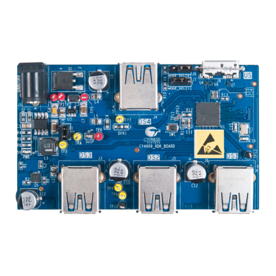
Overview of CY4609 RDK The CY4609 RDK (Figure 3-1 Figure 3-2) enables you to evaluate the features of Cypress's CYUSB330X-68LTXC USB 3.0 hub controller parts. The RDK is powered using an external 5-V/4-A AC-DC power adapter. 3.1.1 CY4609 Board Interfaces Figure 3-1. -
Page 18: Jumper Settings
J7: Pins 2 and 3 factory setting. shorted Figure 3-3 shows the location of pins 1, 2, and 3 on the CY4609 jumper blocks. Pin 1 is marked on the board. Figure 3-3. CY4609 Jumper Block Layout Pin 1 Pin 2 Pin 3 HX3 Kits User Guide, Doc. -
Page 19: Overview Of Cy4603 Dvk
3.2.1 CY4603 Board Interfaces The CY4603 DVK (Figure 3-4) enables you to evaluate the features of Cypress's CYUSB331X-88LTXC USB 3.0 hub controller parts. The board is powered using an external 5-V/4-A AC-DC power adapter. Figure 3-4. CY4603 Board (Top Side) -
Page 20: Jumper Settings
Kit Operation Figure 3-5. CY4603 Board (Bottom Side) 5-V to 3.3-V regulator (U22) 3.3-V to 1.2-V regulator (U21) Power Switch ICs (U7 and U14) 3.2.2 Jumper Settings Table 3-2 describes the default jumper settings for CY4603. Table 3-2. CY4603 Default Jumper Settings Function Jumper Blocks Default Setting... -
Page 21: Overview Of Cy4613 Dvk
The CY4613 DVK (Figure 3-8 Figure 3-8) enables you to evaluate the features of Cypress's CYUSB332X-88LTXC USB 3.0 hub controller parts. The board is powered using an external 12-V / 3-A AC-DC power adapter. Figure 3-7. CY4613 Board (Top Side) Standard USB 3.0... -
Page 22: Jumper Settings
Kit Operation Figure 3-8. CY4613 Board (Bottom Side) RID Resistor (R25) 5-V to 3.3-V Regulator (U25) 3.3-V to 1.2-V Regulator (U24) Power Switch ICs (U8, U14, U17, U26) 3.3.2 Jumper Settings Table 3-3 shows the default jumper settings for CY4613. Table 3-3. -
Page 23: Operating The Kits
Pin 3 Operating the Kits The following sections explain the procedure to operate the kits. These steps are based on CY4609 and they are applicable to CY4603 and CY4613 as well. Unique steps for each kit are specified in the corresponding sections. -
Page 24: Connecting The Board To A Usb 3.0 Pc
Kit Operation Figure 3-10. Powering the Board Hub Suspend Status LED (SUSP) Power LED (PWR) 3.4.2 Connecting the Board to a USB 3.0 PC 1. Connect the micro-B end of the USB cable to the board's upstream port; connect the other end of the cable to the USB 3.0 port on a PC, as shown in Figure 3-11. - Page 25 3. Click Universal Serial Bus controllers to list all the USB devices attached to the PC. The CY4609, CY4603, and CY4613 boards are installed as two hubs: a USB 3.0 Hub and a USB 2.0 MTT Hub. To locate the new hub entries in the Device Manager, detach and attach the USB cable from the upstream port of the CY4609, CY4603, or CY4613 board.
-
Page 26: Usb 3.0 Data Transfer
Note: The Device Manager listing for the USB 3.0 and USB 2.0 MTT hubs can vary based on the host or OS implementation. 4. In the USB 3.0 Hub Properties window, select the Details tab and choose Hardware Ids from the drop-down list. The Cypress VID and PID are displayed, as shown in Figure 3-14. - Page 27 Kit Operation Figure 3-15. USB 3.0 SuperSpeed Data Transfer USB flash drive connected to a downstream port Note: CY4603 and CY4613 have three port status indicator LEDs for each downstream port; Table 3-6 describes their functions. Table 3-6. Port Status Indicator LEDs on CY4603 and CY4613 LEDs Color Behavior...
- Page 28 Kit Operation Figure 3-16. Port Status Indicator LEDs on CY4603 Port Status Indicator LEDs for Downstream Port 1 DS1_SS LEDs (D1 and D13) DS1_GRN LEDs (D2 and D14) DS1_AMB LED (D10) Port Status Indicator LEDs for Downstream Port 2 Port Status Indicator LEDs for Downstream Port 3 Port Status Indicator LEDs for Downstream Port 4...
- Page 29 Kit Operation Figure 3-17. Port Status Indicator LEDs on CY4613 Port Status Indicator LEDs for Downstream Port 1 DS1_SS LEDs (D1 and D13) DS1_GRN LEDs (D2 and D14) DS1_AMB LEDs (D3 and D15) Port Status Indicator LEDs for Downstream Port 2 Port Status Indicator LEDs for Downstream Port 3 Port Status Indicator LEDs...
- Page 30 Kit Operation Table 3-7. Shared GPIOs for Port Status Indicator LED and Pin Strap Feature Active Port Status Indicator Active Port Status Indicator LED Port LED on CY4603 on CY4613 Status Pin Strap Shared Shared GPIO Shared GPIO in Shared GPIO in Indicator GPIO Feature...
- Page 31 Kit Operation Figure 3-19. Data Transfer on Shared Link Ports USB 2.0 flash drive connected to Shared Link standard USB 2.0 downstream port (DS1) USB 3.0 flash drive connected to Shared Link SS downstream port (DS1) Power off the board by disconnecting the AC-DC adapter. Connect a USB 3.0-certified flash drive to a Shared Link SS downstream port (DS1).
-
Page 32: Battery Charging
Kit Operation 3.4.4 Battery Charging Connect an Apple device or a device that is compliant with the USB-IF Battery Charging specifica- tion v1.2 to one of the downstream ports. The connected device is charged by the board (see Figure 3-20). Figure 3-20. -
Page 33: Ghost Charging
5-V/4-A power adapter, ensure that no more than two downstream ports are used as CDP. If the current consumed by the downstream ports exceeds 3.6 A, the CY4609 board detects an overcurrent condition and interrupts HX3, which disables power to all the downstream ports until the overcurrent condition is removed and the board is reset. -
Page 34: Configuring Hx3 Using Pin Straps On Cy4603
Kit Operation 3.4.6 Configuring HX3 Using Pin Straps on CY4603 You can configure HX3 using pin strap GPIOs. The “Configuration Options” section of the HX3 data- sheet gives more details about the use of pin strap GPIOs. A pin strap GPIO can be strapped to logic '1' by shorting pins 1 and 2 using a jumper. - Page 35 2. Enable configuration using pin straps by installing a jumper on pins 1 and 2 of PIN_STRAP_EN (J13 on CY4603). 3. Remove the jumper on VID_SEL[0] to retain the Cypress VID. Note that the DS4_GRN LED func- tionality will be void in this configuration.
-
Page 36: Aca-Dock Feature On Cy4613
Kit Operation 3.4.7 ACA-Dock Feature on CY4613 The ACA-Dock feature helps to demonstrate the USB host functionality while charging. Normally when a host-capable handheld device such as a phone is connected to a device on the DS port, the VBUS is provided by the USB host. When the battery is drained and the host-capable phone needs to be charged, the host functionality cannot be exercised until the phone is charged. - Page 37 Kit Operation Figure 3-24. Demonstrating Battery Charging on Upstream Port Battery charging as per BC v1.2 USB 2.0 ‘micro-B specification to micro-B’ cable connected to the phone 4. Power the HX3 board by connecting the power supply plug to the board's DC supply jack. 5.
-
Page 38: I2C Slave Mode Operation
Kit Operation Figure 3-26. Disabling ACA-Dock Feature in CY4613 Board ACA-Dock jumper settings for disabling the ACA-Dock feature 8. Power off the HX3 board by disconnecting the AC-DC power adapter from the DC jack. Disconnect the phone by detaching the micro-B to micro-B cable from the CY4613 board. 9. - Page 39 Kit Operation Figure 3-27. I C header on CY4603 DVK C Header Figure 3-28. I C header on CY4613 DVK C Header 4. Power on HX3 DVK and the I C master device. Connect HX3 to a PC / laptop. Send the 'HX3 I Slave Mode file' content from the I C master device.
- Page 40 Kit Operation HX3 Kits User Guide, Doc. #: 001-91203 Rev. *D...
-
Page 41: Hx3 Blaster Plus Tool
HX3 Blaster Plus Tool This chapter provides details about the HX3 Blaster Plus tool and the operating procedure with the CY4609, CY4603, and CY4613 kits. Overview HX3 Blaster Plus is a GUI-based tool to configure the HX3 hub controller. It can be used to configure any HX3-based hardware with a compatible EEPROM connected to HX3 over I C. -
Page 42: Procedure To Run The Hx3 Blaster Plus Tool
HX3 Blaster Plus Tool Procedure to run the HX3 Blaster Plus Tool Figure 4-2 provides the steps to run the HX3 Blaster Plus tool with CY4609 or CY4603 boards. Figure 4-2. Steps to Run HX3 Blaster Plus Tool START Connect the HX3 hardware to the PC... -
Page 43: Bind Cyusbhx3 Vendor Driver On The Pc
1. Connect the HX3 board to one of the USB ports. a. Invoke Device Manager and search for a USB 2.0 hub device with the following properties: Table 4-2. Identifying USB 2.0 Hub Hardware VID (hex) PID (hex) CY4609 04B4 6502 CY4603 04B4 6506... - Page 44 HX3 Blaster Plus Tool 2. After the device is identified, right-click and select Update Driver Software; see Figure 4-4. Figure 4-4. Updating Driver Software Note: When the HX3-based hardware is connected to a PC over a USB 3.0 port, the Device Manager will list one hub with USB 2.0 capability and another hub with USB 3.0 capability.
- Page 45 HX3 Blaster Plus Tool Figure 4-5. Searching CYUSBHX3 Driver Figure 4-6. Locating CYUSBHX3 Driver HX3 Kits User Guide, Doc. #: 001-91203 Rev. *D...
- Page 46 HX3 Blaster Plus Tool 4. Click Have Disk, as shown in Figure 4-7. Figure 4-7. Loading CYUSBHX3 Driver Path 5. Click Browse and select the driver file (CyUSBHx3.inf) by navigating to <Install Direc- tory>\HX3 Blaster Plus\drivers\<operating system>\<x64/x86>; click Open, as shown in Figure 4-8.
- Page 47 HX3 Blaster Plus Tool 6. Select Cypress HX3 Vendor Mode, as shown in Figure 4-9. Figure 4-9. Selecting Driver Type 7. Click Yes in the Update Driver Warning window, as shown in Figure 4-10. Figure 4-10. Confirming Installation of Driver...
- Page 48 HX3 Blaster Plus Tool 8. Accept the driver signature by selecting the Always trust software from "Cypress Semiconductor Corporation" check box and click Install; see Figure 4-11. Figure 4-11. Enabling Installation of the Driver 9. When the installation is successful, click Close.
-
Page 49: Configure Hx3 Board Using The Hx3 Blaster Plus Tool
Configure HX3 Board Using the HX3 Blaster Plus Tool 1. Invoke the HX3 Blaster Plus tool from Start > All Programs > Cypress > HX3 Blaster Plus > HX3 Blaster Plus. The HX3 Blaster Plus GUI is displayed as shown in Figure 4-13. - Page 50 HX3 Blaster Plus Tool Table 4-3 provides an overview of the seven groups of configuration settings supported by the HX3 Blaster Plus tool. Table 4-3. Configuration Setting Groups Configuration Setting Description Group This group of parameters is related to the hub descriptor that will be sent to General settings the host;...
- Page 51 HX3 Blaster Plus Tool 2. Select the HX3 device from the Select a HX3 device drop-down list, as shown in Figure 4-15. Figure 4-15. Selecting HX3 Device 3. Select the Configuration type. Figure 4-16. Selecting Configuration Type Configuration type (Configuration A to Configuration D) determines the number of parameters that can be configured using the HX3 Blaster Plus tool GUI.
- Page 52 HX3 Blaster Plus Tool Table 4-4. Configurable Parameters for Each Configuration Type (continued) Configuration Type Configuration Setting Group Configurable Parameters Port Indicators Disable SS LED Disable green LED GPIO control Disable amber LED Suspend indicator disable LED modulate enable Ghost charge enable Battery charging Charging control ACA-Dock...
- Page 53 HX3 Blaster Plus Tool 5. The following example illustrates the procedure to change the PID for the USB 3.0 hub interface and verify the updated PID. a. Click Always display settings from EEPROM check box located near the menu bar to read the current settings stored on the EEPROM.
- Page 54 EEPROM. Figure 4-20. EEPROM Download Confirmation g. Reset the HX3 hardware by pressing the reset switch (SW1 on CY4603 and CY4609). h. Identify the USB 3.0 hub entry in Device Manager for the HX3 hardware and check the PID.
-
Page 55: Generating 'Hx3 I2C Slave Mode File' For Cy4603 And Cy4613 Dvks
HX3 Blaster Plus Tool While specifying value for the configuration parameters, make sure that the HX3 board design ❐ can support the values wherever applicable. For e.g., if the HX3 board design uses 'active low' signal to indicate 'over current' state on downstream port, only 0 can be assigned as the value for 'Over current polarity' parameter in Blaster Plus. -
Page 56: Restoring Cy4613 Dvk To Factory Default Firmware
HX3 Blaster Plus Tool Figure 4-22. Generate HX3 I C Slave Mode File dialog box 4.3.5 Restoring CY4613 DVK to factory default firmware The CY4613 DVK can be restored to factory default firmware using the below mentioned procedure: 1. Power off the CY4613 board and configure it for the ROM firmware mode. Refer to Table 3-4 on page 23 for jumper details. -
Page 57: Uninstall The Cyusbhx3 Vendor Driver
HX3 Blaster Plus tool only. To restore the hub functionality, you need to uninstall the CYUSBHX3 driver associated with the board using the following procedure: 1. Open the Device Manager and locate the Cypress HX3 Vendor Mode device. Right-click the device and select Uninstall, as shown in Figure 4-23. - Page 58 HX3 Blaster Plus Tool HX3 Kits User Guide, Doc. #: 001-91203 Rev. *D...
-
Page 59: Hardware
Hardware This chapter explains the theory of operation and design details for the CY4609, CY4603, and CY4613 hardware. CY4609 RDK Hardware Design 5.1.1 Board Details The CY4609 RDK hardware consists of the following components: CYUSB3304-68LTXC hub controller ■ 5-V DC supply jack to connect the 5-V/4-A power adapter provided as part of the kit ■... -
Page 60: Theory Of Operation
Port 3 Port 4 The CY4609 RDK is based on the CYUSB3304-68LTXC hub controller. It is a small form-factor hard- ware supporting four USB 3.0 downstream ports that conform to USB 3.0 and BC v1.2 specifica- tions. The ports also support Ghost Charging and emulate Apple charging. The upstream port is implemented using a USB 3.0 micro-B connector. -
Page 61: Functional Description
VDDIO 3.3-V I/O supply These power domains can be served using two power supplies (3.3 V and 1.2 V). The CY4609 RDK is designed to support these power supplies using two independent DC-DC regulators. The 5-V sup- ply from the AC-DC adapter is fed to a 5-V-to-3.3-V DC-DC regulator (AOZ1021AI) to create a 3.3-V supply. - Page 62 TP12 TP11 ILIM TPS2556DRBT 100E BSN20-7 0R_0402 Table 5-2 lists the decoupling and bulk capacitors used on CY4609. Table 5-2. Decoupling and Bulk Capacitors on CY4609 Power Domain Bulk Capacitor for the Decoupling Capacitor Description (Pin Numbers) Group Per Pin AVDD12 (10,16,34,46,52) 1.2 V for SS PHY RX...
- Page 63 Hardware 5.1.3.2 Clock and Reset This section describes the hardware circuit implemented for clock and reset aspects as shown in Figure 5-4. Figure 5-4. Clock Design 12pF_50V xtalout XTL_OUT 26MHz xtalin XTL_IN NX3225SA-26.000000MHZ-G4 12pF_50V HX3 requires an external crystal with a frequency of 26 MHz and an accuracy of ±150 ppm in parallel resonant, fundamental mode.
- Page 64 (Figure 5-7). CY4609 uses a micro-B connector for the upstream port and a standard-A con- nector for downstream ports. ESD protection diode ICs are included on all these connectors to sup- port the IEC 610004-5 (level 4) ESD standard.
- Page 65 3PIN JUMPER DEFAULT_OPTION = 2&3 The CY4609 RDK hardware implements two jumpers (J6 and J7). These jumpers are used to spec- ify the boot mode for HX3. Refer to the System Interfaces section of the HX3 datasheet to learn more about how the configuration mode select jumpers work.
- Page 66 WP and GND; it can be enabled by assembling a 0- resistor between WP and V3p3. WP is disabled by default on the CY4609 hardware to enable configuration data to be stored on the EEPROM using the HX3 Blaster Plus tool.
-
Page 67: Cy4603 Dvk Hardware Design
Hardware CY4603 DVK Hardware Design 5.2.1 Board Details The CY4603 DVK hardware consists of the following components: CYUSB3314-88LTXC hub controller ■ Power supply block to provide 5-V, 3.3-V, and 1.2-V outputs ■ Four USB 3.0 downstream ports and one USB 3.0 upstream port ■... -
Page 68: Functional Description
CY4603 uses the same power supply circuit as CY4609 to generate 3.3-V and 1.2-V power supplies. The design of CY4603 differs from that of CY4609 with respect to the implementation of power con- trol. CY4603 implementation supports monitoring an overcurrent condition at each downstream port using a power switch. - Page 69 3.3 V for USB 3.0 PHY 10 µF and 1 µF 0.1 µF and 0.01 µF VDDIO (34,66,88) 3.3 V for I/Os 10 µF 0.1 µF and 0.01 µF Note: Visit www.cypress.com/hx3 for schematics with a reduced BOM. HX3 Kits User Guide, Doc. #: 001-91203 Rev. *D...
- Page 70 5.2.3.2 LEDs and Jumpers CY4603 uses the same circuit as CY4609 for the boot mode selection jumper and for the Power (PWR) and Suspend (SUSP) LEDs. However, CY4603 implements three LEDs per downstream port to indicate SuperSpeed (blue), USB 2.0 (green), and exception (amber) status.
- Page 71 CY4603 uses the same clock and reset circuit as CY4609. 5.2.3.5 USB Ports CY4603 implements an upstream connector interface using a standard-B connector instead of a micro-B connector as in CY4609, but CY4603 uses the same downstream port circuit as CY4609. 5.2.3.6 Test Points Table 5-6 lists the test points available on the CY4603 hardware and the associated signal names.
-
Page 72: Cy4613 Dvk Hardware Design
Hardware CY4613 DVK Hardware Design 5.3.1 Board Details The CY4613 DVK hardware consists of the following components: CYUSB3328-88LTXC hub controller. It is an 8-port Shared Link part, which is configured using ■ the Blaster Plus tool for six-port operation on the CY4613 board Power supply block to provide 5-V, 3.3-V, and 1.2-V outputs ■... -
Page 73: Functional Description
5 A to prevent excess heating of the 12-V to 5-V DC-DC regulator. CY4613 uses the same power circuit as the CY4609 to generate the 3.3-V and 1.2-V supplies. A Ferrite Bead (L12) is used at the input of the 3.3-V regulator to remove excess ripple from the 12-V to 5-V DC-DC regulator. - Page 74 Shared Link Implementation Shared Link is a Cypress-proprietary feature that enables a USB 3.0 port to be split into an embed- ded SS port and a standard USB 2.0 port. For example, if one of the DS ports is connected to an embedded SS device, HX3 enables the system designer to reuse the USB 2.0 signals of that spe-...
- Page 75 Power Source Note: The RID resistor value may require change for docking applications targeted for some specific hosts, which are not compliant to the BC v1.2 specification. Contact Cypress Technical Support at cypress.com/go/support to get more details. CY4613 supports the ACA-Dock feature (BC v1.2 compliant). The following three jumpers are used to set up the ACA-Dock feature.
- Page 76 Hardware Table 5-9. CY4613 Test Points (continued) Test Point Signal Name V3P3 V1P2 TP10 Overcurrent for US port TP11 Power Enable for US port TP12 VBUS Power for DS4 port TP13 Power Enable for DS4 port TP14 Serial Data for I TP15 Serial Clock for I TP16...
-
Page 77: Appendix
Appendix Troubleshooting Guide Table A-1. Troubleshooting the CY4609, CY4603, and CY4613 Kits Applicable Problem Possible Cause Possible Solution Kits Ensure that the jumper on the current The jumper on the current mea- measurement header (J2 on CY4609, surement header may not have... - Page 78 Table A-1. Troubleshooting the CY4609, CY4603, and CY4613 Kits (continued) Applicable Problem Possible Cause Possible Solution Kits Ensure that the pin strap feature is The pin strap feature may not enabled by shorting pins 1 and 2 of the have been enabled.
- Page 79 Table A-1. Troubleshooting the CY4609, CY4603, and CY4613 Kits (continued) Applicable Problem Possible Cause Possible Solution Kits Remove the jumper from one of the three VID_SEL[0-2] jumper blocks to When the pin strap restore Cypress VID. Note that the Cypress VID is not supported if...
- Page 80 Table A-1. Troubleshooting the CY4609, CY4603, and CY4613 Kits (continued) Applicable Problem Possible Cause Possible Solution Kits DS19 and DS21 LEDs glow after Repeat the procedure to put the kit in restoring the kit to Shared Link feature may not...
-
Page 81: Hardware Design Details
Hardware Design Details A.2.1 CY4609 RDK Schematics Figure A-1. Voltage Regulators POWER SUPPLY VCC_5V 5V @ 5A ADAPTER INPUT 3.3V @ 3A REGULATOR (3A) V3p3 5V@5A DC INPUT SUD50P04-09L-E3 4.7uH HDR_1X2 Jumper for Current PJ-102BH Consumption Measurement 0.1UF_16V 10UF_16V 150R 22uF_16V 7.5K... - Page 82 PART_NUMBER = NCP361SNT1G Size Size Size Document Number Document Number Document Number Manufacturer = ON Semiconductor Custom Custom Custom CY4609-RDK-BOARD CY4609-RDK-BOARD CY4609-RDK-BOARD NCP361SNT1G Date: Date: Date: Tuesday, January 21, 2014 Tuesday, January 21, 2014 Tuesday, January 21, 2014 Sheet Sheet Sheet HX3 Kits User Guide, Doc.
- Page 83 Size Size Document Number Document Number Document Number Connect the HX3 EPAD to GND through the via stitches. Custom Custom Custom CY4609-RDK-BOARD CY4609-RDK-BOARD CY4609-RDK-BOARD Date: Date: Date: Tuesday, January 21, 2014 Tuesday, January 21, 2014 Tuesday, January 21, 2014 Sheet...
-
Page 84: Cy4603 Dvk Schematics
A.2.2 CY4603 DVK Schematics Figure A-4. Voltage Regulators POWER SUPPLY VCC_5V 3.3V @ 3A REGULATOR (3A) V3p3 5V@6A DC INPUT SUD50P04-09L-E3 4.7uH HDR_1X2 PJ-102BH Jumper for Current 0.1UF_16V 10UF_16V Consumption Measurement 330R 22uF_16V 7.5K 22uF_10V LTST-C190KGKT COMP GREEN 2.4K AOZ1021AI 7.5K 2.2nF 1.2V @ 1.5A REGULATOR... - Page 85 Figure A-5. Overvoltage, Overcurrent Protection, and Decoupling Capacitors POWER & DECOUPLING V1p2 DVDD12 V1p2 DVDD12_1 DVDD12_5 BLM21PG221SN1D DVDD12_2 DVDD12_6 DVDD12_3 DVDD12_7 DVDD12_4 DVDD12_8 DVDD12_9 V3p3 VDDIO1 VDDIO2 VDDIO3 AVDD12_1 AVDD12_2 AVDD12_3 AVDD12_4 AVDD12_5 AVDD33_9 BLM21PG221SN1D AVDD33_6 AVDD33_7 AVDD12_6 AVDD33_8 CYUSB3314-88LTXC USB POSITIVE OVERVOLTAGE &...
- Page 86 Custom Custom CY4603-DVK-BOARD CY4603-DVK-BOARD CY4603-DVK-BOARD Date: Date: Date: Wednesday, January 22, 2014 Wednesday, January 22, 2014 Wednesday, January 22, 2014 Sheet Sheet Sheet Note: Visit www.cypress.com/hx3 for schematics with reduced BOM. HX3 Kits User Guide, Doc. #: 001-91203 Rev. *D...
- Page 87 Figure A-7. LEDs POWER SWITCHES & LED'S V3p3 SWD Interface Program/Debug Header V3p3 V3p3 HSMA-C190 3PIN JUMPER V3p3 DS1_AMB DS1_PWREN DS1_AMBER/ACA_DOCK CDP_DS1_EN/DS1_PWREN V3p3 270R DS2_PWREN 3PIN JUMPER SWD_IO CDP_DS2_EN/DS2_PWREN SWD_CLK DS3_PWREN V3p3 CDP_DS3_EN/DS3_PWREN LTST-C190KGKT 0402 300R PORT_DIS[0] DS4_PWREN 0.1uF_16V DS1_GREEN/PORT_DISABLE[0] CDP_DS4_EN/DS4_PWREN RESET_SWD V3p3...
-
Page 88: Cy4613 Dvk Schematics
A.2.3 CY4613 DVK Schematics Figure A-8. CY4613 Schematics for Voltage Regulators POWER SUPPLY 5V@5A PWR SWITCH VCC_5V 12V DC INPUT SUD50P04-09L-E3 VOUT OUT1 C101 TRIM OUT2 C102 0.1UF_16V 10UF_16V C105 ENABLE PJ-102AH FAULT 10uF_25V 267R 0.1UF_16V 10UF_16V 330R GREEN OKR_T_6 LED24 LTST-C190KGKT ILIM... - Page 89 Figure A-9. CY4613 Schematics for Overvoltage, Overcurrent Protection, and Decoupling Capacitors POWER & DECOUPLING V1p2 DVDD12 V1p2 DVDD12_1 DVDD12_5 BLM21PG221SN1D VDD_EFUSE DVDD12_6 DVDD12_3 DVDD12_7 DVDD12_4 DVDD12_8 DVDD12_9 V3p3 VDD_IO1 VDD_IO2 VDD_IO3 AVDD12_1 AVDD12_2 AVDD12_3 AVDD12_4 AVDD12_5 AVDD33_9 BLM21PG221SN1D AVDD33_6 AVDD33_7 AVDD12_6 AVDD33_8 CYUSB3324-88LTXC...
- Page 90 Custom Custom 630-60156-01 630-60156-01 630-60156-01 Date: Date: Date: Thursday, June 12, 2014 Thursday, June 12, 2014 Thursday, June 12, 2014 Sheet Sheet Sheet Note: Visit www.cypress.com/hx3 for schematics with reduced BOM. HX3 Kits User Guide, Doc. #: 001-91203 Rev. *D...
- Page 91 Figure A-11. CY4613 Schematics for Power Switches and LEDs V3p3 POWER SWITCHES & LED'S V3p3 SWD Interface Program/Debug Header LED3 HSMA-C190 ACA_DOCK 300R V3p3 V3p3 270R 3PIN JUMPER 3PIN JUMPER V3p3 HSMA-C190 DS1_PWREN DS1_AMBER/GPIO2 DS1_PWREN/GPIO16 DS2_PWREN SWD_IO 3PIN JUMPER DS2_PWREN/GPIO9 C106 SWD_CLK DS3_PWREN...
- Page 92 HX3 Kits User Guide, Doc. #: 001-91203 Rev. *D...
-
Page 93: Revision History
Revision History Document Revision History Document Title: CY4609, CY4603, and CY4613 HX3 Kits User Guide Document Number: 001-91203 Origin of Revision Issue Date Description of Change Change 02/25/2014 SELV New kit guide. 04/11/2014 SHEA Corrected the document number in the Revision History table. - Page 94 Index HX3 Kits User Guide, Doc. #: 001-91203 Rev. *D...
Need help?
Do you have a question about the CY4609 and is the answer not in the manual?
Questions and answers