Table of Contents
Advertisement
Quick Links
EZ-BLE™ PRoC™ Module
General Description
The CYBLE-01201X-X0 is a Bluetooth
wireless module solution. The CYBLE-01201X-X0 is a turnkey
solution and includes onboard crystal oscillators, trace antenna,
passive components, and the Cypress PRoC™ BLE. Refer to
the CYBL10X6X
datasheet
ities of the PRoC BLE device used on this module.
The CYBLE-01201X-X0 supports a number of peripheral
functions
(ADC,
timers,
communication protocols (I
programmable architecture. The CYBLE-01201X-X0 includes a
royalty-free BLE stack compatible with Bluetooth 4.1 and
provides up to 23 GPIOs in a 14.52 × 19.20 × 2.00 mm package.
The CYBLE-01201X-X0 is available in a fully certified and
qualified version (CYBLE-012011-00), and an uncertified version
(CYBLE-012012-10). The CYBLE-012012-10 does not include
an RF shield and is not certified by Bluetooth SIG or refulatory
agencies.
The CYBLE-01201X-X0 is a complete solution targeted at appli-
cations requiring cost optimized BLE wireless connectivity.
Module Description
■
Module size: 14.52 mm ×19.20 mm × 2.00 mm (with shield)
■
Castelated solder pad connections for ease-of-use
■
128-KB flash memory, 16-KB SRAM memory
■
Up to 23 GPIOs configurable as open drain high/low,
pull-up/pull-down, HI-Z analog, HI-Z digital, or strong output
■
Bluetooth 4.1 qualified single-mode module
❐
QDID:
79919
(CYBLE-012011-00 only)
❐
Declaration ID:
D029885
■
Certified to FCC, IC, MIC, KC, and CE regulations
■
Industrial temperature range: –40 °C to +85 °C
■
32-bit processor (0.9 DMIPS/MHz) with single-cycle 32-bit
multiply, operating at up to 48 MHz
■
Watchdog timer with dedicated internal low-speed oscillator
(ILO)
■
Two-pin SWD for programming
Power Consumption
■
TX output power: –18 dbm to +3 dbm
■
Received signal strength indicator (RSSI) with 1-dB resolution
■
TX current consumption of 15.6 mA (radio only, 0 dbm)
■
RX current consumption of 16.4 mA (radio only)
Cypress Semiconductor Corporation
Document Number: 002-02521 Rev. *F
Low Energy (BLE)
for additional details on the capabil-
counters,
PWM)
and
2
C, UART, SPI) through its
(CYBLE-012011-00 only)
•
198 Champion Court
EZ-BLE™ PRoC™ Module
■
Low power mode support
❐
Deep Sleep: 1.3 µA with watch crystal oscillator (WCO) on
❐
Hibernate: 150 nA with SRAM retention
❐
Stop: 60 nA with GPIO (P2.2) or XRES wakeup
Functional Capabilities
■
Up to 22 capacitive sensors for buttons or sliders with
best-in-class signal-to-noise ratio (SNR) and liquid tolerance
■
12-bit, 1-Msps SAR ADC with internal reference,
serial
sample-and-hold (S/H), and channel sequencer
■
Two serial communication blocks (SCBs) supporting I
(master/slave), SPI (master/slave), or UART
■
Four dedicated 16-bit timer, counter, or PWM blocks
(TCPWMs)
■
LCD drive supported on all GPIOs (common or segment)
■
Programmable low voltage detect (LVD) from 1.8 V to 4.5 V
2
■
I
S master interface
■
Bluetooth Low Energy protocol stack supporting generic
access profile (GAP) Central, Peripheral, Observer, or
Broadcaster roles
■
Switches between Central and Peripheral roles on-the-go
■
Standard Bluetooth Low Energy profiles and services for
interoperability
■
Custom profile and service for specific use cases
Benefits
The CYBLE-01201X-X0 module is provided as a turnkey
solution, including all necessary hardware required to use BLE
communication standards.
■
Proven hardware design ready to use
■
Cost optimized for applications without space constraint,
Footprint
❐
14.52 × 19.20 mm × 2.00 mm - CYBLE-012011-00
❐
14.52 × 19.20 mm × 1.55 mm - CYBLE-012012-10
■
Reprogrammable architecture
■
Fully certified module (CYBLE-012011-00) eliminates the time
needed for design, development and certification processes
■
Bluetooth SIG qualified with QDID and Declaration ID
(CYBLE-012011-00 Only)
■
Flexible communication protocol support
™
■
PSoC Creator
environment (IDE) to configure, develop, program, and test a
BLE application
•
San Jose
CYBLE-012011-00
CYBLE-012012-10
provides an easy-to-use integrated design
,
CA 95134-1709
•
Revised April 25, 2017
2
C
408-943-2600
Advertisement
Table of Contents

Related Manuals for Cypress EZ-BLE PRoC CYBLE-012011-00


Summary of Contents for Cypress EZ-BLE PRoC CYBLE-012011-00
- Page 1 The CYBLE-01201X-X0 is a turnkey ❐ Stop: 60 nA with GPIO (P2.2) or XRES wakeup solution and includes onboard crystal oscillators, trace antenna, passive components, and the Cypress PRoC™ BLE. Refer to Functional Capabilities the CYBL10X6X datasheet for additional details on the capabil- ■...
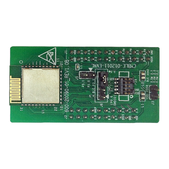
- Page 2 EZ-BLE™ PRoC™ Evaluation Board ■ PRoC BLE Silicon Datasheet (CYBLE-012011-EVAL) and the BLE Pioneer Kit ■ Application notes: Cypress offers a number of BLE application (CY8CKIT-042-BLE) notes covering a broad range of topics, from basic to advanced ❐ KBA97095 - EZ-BLE™ Module Placement level.
-
Page 3: Table Of Contents
Serial Communication ..........22 Products ..............39 Memory ..............23 PSoC® Solutions ............39 System Resources ............ 23 Cypress Developer Community......... 39 Environmental Specifications ........29 Technical Support ............. 39 Environmental Compliance ........29 RF Certification............29 Safety Certification ............ 29 Environmental Conditions ......... -
Page 4: Overview
Module Dimensions and Drawing Cypress reserves the right to select components (including the appropriate BLE device) from various vendors to achieve the BLE module functionality. Such selections will still guarantee that all height restrictions of the component area are maintained. Designs... - Page 5 CYBLE-012011-00 CYBLE-012012-10 Figure 1. Module Mechanical Drawing Top View Side View Bottom View Note 1. No metal should be located beneath or above the antenna area. Only bare PCB material should be located beneath the antenna area. For more information on recommended host PCB layout, see Figure Figure...
-
Page 6: Pad Connection Interface
To maximize RF performance, the host layout should follow these recommendations: 1. The ideal placement of the Cypress BLE module is in a corner of the host board with the trace antenna located at the far corner. This placement minimizes the additional recommended keep out area stated in item 2. Refer to... -
Page 7: Recommended Host Pcb Layout
CYBLE-012011-00 CYBLE-012012-10 Recommended Host PCB Layout Figure Figure Figure 6, and Table 3 provide details that can be used for the recommended host PCB layout pattern for the CYBLE-01201X-X0. Dimensions are in millimeters unless otherwise noted. Pad length of 1.27 mm (0.635 mm from center of the pad on either side) shown in Figure 6 is the minimum recommended host pad length. - Page 8 CYBLE-012011-00 CYBLE-012012-10 Table 3 provides the center location for each solder pad on the CYBLE-01201X-X0. All dimensions are referenced to the center of the solder pad. Refer to Figure 6 for the location of each module solder pad. Table 3. Module Solder Pad Location Figure 6.
-
Page 9: Digital And Analog Capabilities And Connections
4. When using the capacitive sensing functionality, Pad 2 (P4.0) must be connected to a C capacitor (located off of Cypress BLE Module). The value of this capacitor is 2.2 nF and should be placed as close to the module as possible. -
Page 10: Power Supply Connections And Recommended External Components
CYBLE-012011-00 CYBLE-012012-10 Power Supply Connections and Recommended External Components Power Connections External Component Recommendation The CYBLE-01201X-X0 contains two power supply connections, In either connection scenario, it is recommended to place an VDD and VDDR. The VDD connection supplies power for both external ferrite bead between the supply and the module digital and analog device operation. - Page 11 CYBLE-012011-00 CYBLE-012012-10 Figure 8. Recommended Host Schematic for an Independent Supply Option Independent Power Supply Option (Seen from Bottom) Document Number: 002-02521 Rev. *F Page 11 of 39...
- Page 12 CYBLE-012011-00 CYBLE-012012-10 The CYBLE-01201X-X0 schematic is shown in Figure Figure 9. CYBLE-01201X-X0 Schematic Diagram Document Number: 002-02521 Rev. *F Page 12 of 39...
-
Page 13: Critical Components List
CYBLE-012011-00 CYBLE-012012-10 Critical Components List Table 5 details the critical components used in the CYBLE-01201X-X0 module. Table 5. Critical Component List Component Reference Designator Description Silicon 56-pin QFN Programmable Radio-on-Chip (PRoC) with BLE Crystal 24.000 MHz, 12PF Crystal 32.768 kHz, 12.5PF Antenna Design Table 6 details trace antenna used in the CYBLE-01201X-X0 module. -
Page 14: Electrical Specification
CYBLE-012011-00 CYBLE-012012-10 Electrical Specification Table 7 details the absolute maximum electrical characteristics for the Cypress BLE module. Table 7. CYBLE-01201X-X0 Absolute Maximum Ratings Parameter Description Units Details/Conditions Analog, digital, or radio supply relative to V –0.5 – Absolute maximum DDD_ABS Direct digital core voltage input relative to V –0.5... - Page 15 CYBLE-012011-00 CYBLE-012012-10 Table 9. CYBLE-01201X-X0 DC Specifications (continued) Parameter Description Units Details/Conditions Execute from flash; CPU at 12 MHz – – – T = –40 °C to 85 °C T = 25 °C, Execute from flash; CPU at 24 MHz –...
-
Page 16: Gpio
CYBLE-012011-00 CYBLE-012012-10 Parameter Description Units Details/Conditions 1.71 V V 5.5 V CPU frequency – Wakeup from Sleep mode – – µs Guaranteed by characterization SLEEP 24-MHz IMO. Guaranteed by Wakeup from Deep-Sleep mode – – µs DEEPSLEEP characterization Wakeup from Hibernate mode –... -
Page 17: Xres
CYBLE-012011-00 CYBLE-012012-10 Table 12. GPIO AC Specifications Parameter Description Units Details/Conditions Rise time in Fast-Strong mode – 3.3-V V = 25 pF RISEF LOAD Fall time in Fast-Strong mode – 3.3-V V = 25 pF FALLF LOAD Rise time in Slow-Strong mode –... - Page 18 CYBLE-012011-00 CYBLE-012012-10 Table 16. XRES AC Specifications Parameter Description Units Details/Conditions Reset pulse width – – µs – RESETWIDTH Temperature Sensor Table 17. Temperature Sensor Specifications Parameter Description Units Details/Conditions Temperature-sensor accuracy –5 ±1 °C –40 to +85 °C SENSACC SAR ADC Table 18.
- Page 19 CYBLE-012011-00 CYBLE-012012-10 Table 19. SAR ADC AC Specifications (continued) Details/ Parameter Description Units Conditions A_INL Integral nonlinearity. V = 1.71 V to –1.5 – = 1 V to V 5.5 V, 500 ksps A_dnl Differential nonlinearity. V = 1.71 V to –1 –...
-
Page 20: Digital Peripherals
CYBLE-012011-00 CYBLE-012012-10 Digital Peripherals Timer Table 20. Timer DC Specifications Parameter Description Units Details/Conditions Block current consumption at 3 MHz – – µA 16-bit timer TIM1 Block current consumption at 12 MHz – – µA 16-bit timer TIM2 Block current consumption at 48 MHz –... - Page 21 CYBLE-012011-00 CYBLE-012012-10 Pulse Width Modulation (PWM) Table 24. PWM DC Specifications Parameter Description Units Details/Conditions Block current consumption at 3 MHz – – µA 16-bit PWM PWM1 Block current consumption at 12 MHz – – µA 16-bit PWM PWM2 Block current consumption at 48 MHz –...
-
Page 22: Serial Communication
CYBLE-012011-00 CYBLE-012012-10 Serial Communication Table 28. Fixed I C DC Specifications Parameter Description Units Details/Conditions Block current consumption at 100 kHz – – µA – I2C1 Block current consumption at 400 kHz – – µA – I2C2 Block current consumption at 1 Mbps –... -
Page 23: Memory
CYBLE-012011-00 CYBLE-012012-10 Table 35. Fixed SPI Slave Mode AC Specifications (continued) Parameter Description Units Details/Conditions Previous MISO data hold time – – SSEL valid to first SCK valid edge – – SSELSCK Memory Table 36. Flash DC Specifications Parameter Description Units Details/Conditions Erase and program voltage... -
Page 24: System Resources
CYBLE-012011-00 CYBLE-012012-10 System Resources Power-on-Reset (POR) Table 38. POR DC Specifications Parameter Description Units Details/Conditions Rising trip voltage 0.80 – 1.45 – RISEIPOR Falling trip voltage 0.75 – 1.40 – FALLIPOR Hysteresis – – IPORHYST Table 39. POR AC Specifications Parameter Description Units... - Page 25 CYBLE-012011-00 CYBLE-012012-10 Table 43. Voltage Monitor AC Specifications Parameter Description Units Details/Conditions Voltage monitor trip time – – µs – MONTRIP SWD Interface Table 44. SWD Interface Specifications Parameter Description Units Details/Conditions 3.3 V V 5.5 V SWDCLK 1/3 CPU clock frequency F_SWDCLK1 –...
- Page 26 CYBLE-012011-00 CYBLE-012012-10 BLE Subsystem Table 50. BLE Subsystem Details/ Parameter Description Units Conditions RF Receiver Specification RXS, IDLE RX sensitivity with idle transmitter – –89 – RX sensitivity with idle transmitter – –91 – Guaranteed by design excluding Balun loss simulation RXS, DIRTY RX sensitivity with dirty transmitter...
- Page 27 CYBLE-012011-00 CYBLE-012012-10 Details/ Parameter Description Units Conditions RXSE2 Receiver spurious emission – – –47 1-MHz measurement 1.0 GHz to 12.75 GHz bandwidth ETSI EN300 328 V1.8.1 RF Transmitter Specifications TXP, ACC RF power accuracy – ±1 – TXP, RANGE RF power control range –...
- Page 28 CYBLE-012011-00 CYBLE-012012-10 Details/ Parameter Description Units Conditions ITX,-18dBm TX current at –18-dBm setting (PA1) – 12.5 – Iavg_1sec, 0dBm Average current at 1-second BLE – 17.1 – µA TXP: 0 dBm; ±20-ppm connection interval master and slave clock accuracy. For empty PDU exchange Iavg_4sec, 0dBm Average current at 4-second BLE –...
-
Page 29: Environmental Specifications
Environmental Specifications Environmental Compliance This Cypress BLE module is built in compliance with the Restriction of Hazardous Substances (RoHS) and Halogen Free (HF) directives. The Cypress module and components used to produce this module are RoHS and HF compliant. RF Certification The CYBLE-012011-00 module will be certified under the following RF certification standards at production release. -
Page 30: Regulatory Information
The Original Equipment Manufacturer (OEM) must ensure that FCC labelling requirements are met. This includes a clearly visible label on the outside of the OEM enclosure specifying the appropriate Cypress Semiconductor FCC identifier for this product as well as the FCC Notice above. The FCC identifier is FCC ID: WAP2011. -
Page 31: Industry Canada (Ic) Certification
The Original Equipment Manufacturer (OEM) must ensure that IC labelling requirements are met. This includes a clearly visible label on the outside of the OEM enclosure specifying the appropriate Cypress Semiconductor IC identifier for this product as well as the IC Notice above. -
Page 32: Mic Japan
CYBLE-012011-00 CYBLE-012012-10 MIC Japan CYBLE-012011-00 is certified as a module with type certification number 203-JN0509. End products that integrate CYBLE-012011-00 do not need additional MIC Japan certification for the end product. End product can display the certification label of the embedded module. KC Korea CYBLE-012011-00 is certified for use in Korea with certificate number MSIP-CRM-Cyp-2011. -
Page 33: Packaging
CYBLE-012011-00 CYBLE-012012-10 Packaging Table 52. Solder Reflow Peak Temperature Maximum Time at Peak Module Part Number Package Maximum Peak Temperature No. of Cycles Temperature CYBLE-01201X-X0 31-pad SMT 260 °C 30 seconds Table 53. Package Moisture Sensitivity Level (MSL), IPC/JEDEC J-STD-2 Module Part Number Package CYBLE-01201X-X0... - Page 34 CYBLE-012011-00 CYBLE-012012-10 Figure 12 details reel dimensions used for the CYBLE-01201X-X0. Figure 12. Reel Dimensions The CYBLE-01201X-X0 is designed to be used with pick-and-place equipment in an SMT manufacturing environment. The center-of-mass for the CYBLE-01201X-X0 is detailed in Figure Figure 13. CYBLE-01201X-X0 Center of Mass (Seen from Top) Document Number: 002-02521 Rev.
-
Page 35: Ordering Information
The part numbers are of the form CYBLE-ABCDEF-GH where the fields are defined as follows. For additional information and a complete list of Cypress Semiconductor BLE products, contact your local Cypress sales representative. To locate the nearest Cypress office, visit our website. -
Page 36: Document Conventions
CYBLE-012011-00 CYBLE-012012-10 Acronym Description Bluetooth SIG Bluetooth Special Interest Group European Conformity Canadian Standards Association electromagnetic interference electrostatic discharge Federal Communications Commission GPIO general-purpose input/output Industry Canada integrated design environment Korea Certification Ministry of Internal Affairs and Communications (Japan) printed circuit board receive QDID qualification design ID... -
Page 37: Document History Page
CYBLE-012011-00 CYBLE-012012-10 Document History Page Document Title: CYBLE-012011-00/CYBLE-012012-10, EZ-BLE™ PRoC™ Module Document Number: 002-02521 Orig. of Submission Revision Description of Change Change Date 4998892 MINS 10/22/2015 Preliminary datasheet for CYBLE-01201X-X0 module. 5060713 01/07/2016 Updated General Description to add reference and link to PRoC BLE silicon datasheet. - Page 38 Updated Table 18 to add Note 8 to specify under what conditions the maximum number of ADC channels can be achieved. 5709491 GNKK 04/25/2017 Updated the Cypress logo and copyright information. Document Number: 002-02521 Rev. *F Page 38 of 39...
-
Page 39: Sales, Solutions, And Legal Information
("Unintended Uses"). A critical component is any component of a device or system whose failure to perform can be reasonably expected to cause the failure of the device or system, or to affect its safety or effectiveness. Cypress is not liable, in whole or in part, and you shall and hereby do release Cypress from any claim, damage, or other liability arising from or related to all Unintended Uses of Cypress products.
Need help?
Do you have a question about the EZ-BLE PRoC CYBLE-012011-00 and is the answer not in the manual?
Questions and answers