Star Trac 8-TRx Service Manual
Core health & fitness
Hide thumbs
Also See for 8-TRx:
- Assembly manual (8 pages) ,
- Service bulletin (8 pages) ,
- Installation instructions (2 pages)
Table of Contents
Advertisement
Advertisement
Table of Contents

Related Manuals for Star Trac 8-TRx


Summary of Contents for Star Trac 8-TRx
- Page 1 Core Health & Fitness Startrac® Treadmills SERVICE MANUAL...
- Page 2 TABLE OF CONTENTS Click any text to jump to section PRODUCT SPOTLIGHT ............................. 3 SAFETY INFORMATION ............................. 6 OTHER MANUALS ............................. 8 PART IDENTIFICATION ............................. 9 Drive System ..................9 Power System ..................13 Belt & Deck System ..................16 Elevation System ..................19 Wiring Diagrams ..................20...
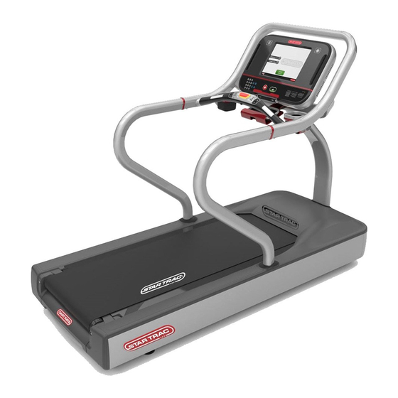
- Page 3 Quick Links: • Identify a product by Serial Number • General Warranty Terms • About Extended Warranties 8 Series Treadmills 9-920X 8-TRx 9-925X 8-TRx Overall Weight Running Surface Width Length Height 477 lbs (216 kg) 60˝ x 21.5˝ (152 x 55 cm) 36˝...
- Page 4 E Series Treadmills 9-90XX E-TRx 9-911X E-TRxe Overall Weight Running Surface Width Length Height 477 lbs (216.4 kg) 60˝ x 21.5˝ (152 x 55 cm) 36˝ (91 cm) 85˝ (215 cm) 63˝ (160 cm) 9-9101 E-TRxi Overall Weight Running Surface Width Length Height...
- Page 5 S Series Treadmills 9-35XX S-TRc Overall Weight Running Surface Width Length Height 533 lbs (241.7 kg) 60˝ x 20˝ (152 x 51 cm) 32˝ (81.3 cm) 81˝ (206 cm) 58˝ (147.3 cm) 9-355X 9-356X S-TRx Overall Weight Running Surface Width Length Height 514 lbs (233.2 kg)
- Page 6 SAFETY INFORMATION Danger: Treadmill maintenance requires the power to be on. Please exercise caution when working around live electrical components circuit, the reconnection should be made by qual- Core Health & Fitness requires a dedicated, ified service personnel in order to avoid a hazard. isolated 20 Amp circuit (no shared grounds, positives, or neutrals) for each treadmill.
- Page 7 training envelope and any other national or local codes or regulations. Keep power cord away from heated surfaces. Unplug power cord when the machine is unat- tended and before performing any preventative maintenance such as cleaning or replacing a worn part. Familiarize yourself with the location of the STOP buttons on the console.
- Page 8 OTHER MANUALS Click the links below to load the related complete manuals from our support website. Safety warnings specific to each unit are located in their respective owner’s manuals. Manuals Install Owner’s 8-TRx 8-TRx 8-TR E-TRx E-TRxe E-TRxi E-TR E-TRi...
- Page 9 PART IDENTIFICATION The drive system is what makes the treadmill running belt move as well as what sends feedback to the display for keeping track of speed. The Display Electronics reads the speed from the RPM Sensor and instructs the Motor Control Board (MCB) to turn the Drive Motor as needed. Drive System The MCB controls the power flow throughout the unit based on the commands from the display board.
- Page 10 Motor Control Board (MCB) 8-TRx, 8-TR, E-TRx, & E-TR 110V Version - Part # 715-3881 220V Version - Part # 715-3880 Pinout S-TR, S-TRx, S-TRc 110V Version - Part # 740-6002 220V Version - Part # 740-6003 Pinout Note: click links to load diagram and pinout from our support site The MCB converts the incoming wall power to power to 12.6 volt VDC to send up the display cable...
- Page 11 PIN 1 Part # 715-4046 Pinout Note: click links to load diagram and pinout from our support site Drive Motor 8-TRx, 8-TR, E-TRx, & E-TR Part # 715-3885 Note: For E-TRx units built prior to 2009 click here. S-TR, S-TRx, S-TRc...
- Page 12 Display Electronics The display electronics consist of either a single board in the case of the LED screens that have both the processor and the LED’s, or in the case of embedded screens, the display electronics refer col- lectively to the Upper Board that has the processor and the Digitizer, which displays the image and responds to touch.
- Page 13 Power System The power system supplies AC and DC voltage to different components of the treadmill. There are two parts of the power system, external power and internal power. All external components beyond the power cable are not covered by this manual and are assumed to be working in any trouble- shooting step.
- Page 14 IEC Connector Part # 740-6083 Circuit Breaker 110V Version - Part # 470-0417 220V Version - Part # 470-0415 EMI Filter Part #440-0257 Basic Diagram Page 14...
- Page 15 Power Cord Pinout 110V Version - Part # 220-0278 220V Version - Part # 220-0277 All US units in this manual come with one of the cords shown above or equivalent. Complete list of alternate cords is below: 220-0270 ADAPTER, CORD LINE, NEMA 5-15 220-0271 ADAPTER, CORD LINE, NEMA 6-15 220-0272...
- Page 16 Belt/Deck Detail Belt & Deck System The belt and deck system is the main function of the treadmill. The drive belt connects the drive motor to the head roller. The tail roller is used for tensioning and tracking of the running belt. The running belt goes around the two rollers and the deck.
- Page 17 GEN 1: S-TR, S-TRx, S-TRc Part # 740-6055 GEN 2: S-TR, S-TRx, S-TRc Part # 715-3897 Running Belt 8-TRx, 8-TR, E-TRx, & E-TR Part # 130-1759 GEN 1: S-TR, S-TRx, & S-TRc Part # 130-1708 Note: Click Here for units prior to serial TRSC1307-L01095 (110V) or TRSC1306-L01000 (220V) GEN 2: S-TR, S-TRx, &...
- Page 18 Deck 8-TRx, 8-TR, E-TRx, & E-TR Part # 715-3689-KT GEN 1: S-TR, S-TRx, & S-TRc Part # 800-3874 GEN 2: S-TR, S-TRx, & S-TRc Part # 715-3689-KT Tail Roller 8-TRx, 8-TR, E-TRx, & E-TR Part # 715-3635 GEN1: S-TR, S-TRx, S-TRc...
- Page 19 The elevation system controls the incline of the treadmill. Components include the display electron- ics, Data Cable, MCB, & Elevation Motor which includes the Elevation Sensor (Potentiometer) Elevation Motor 8-TRx & E-TRx 110V Version Part # 260-0941 220V Version Part # 260-0942 8-TR &...
- Page 20 (Variable)VDC Elevation FromPotentiometer Motor 8 Series Diagrams 8-TRx - 110v Base 8-TRx - 220v Base 8-TRx - LCD Display 8-TRx - Embedded Display 8-TRxi (Israel) - 220v Base Page 20...
- Page 21 Click on an icon to open the diagram in a new window. Click the button in the upper right to close the new view and return to the service manual. Note: these buttons will not work in a browser window. Right click > Save As or click the button in your browser to save this manual to your PC.
- Page 22 Click on an icon to open the diagram in a new window. Click the button in the upper right to close the new view and return to the service manual. Note: these buttons will not work in a browser window. Right click > Save As or click the button in your browser to save this manual to your PC.
- Page 23 CONSOLES The 8 Series treadmills in this manual use the OpenHub consoles. Although the 15” Embedded ver- sion is pictured above, the OpenHub also includes other variations for embedded and LCD screens. Complete details on the OpenHub manuals as well as all troubleshooting for them are located in the OpenHub Service Manual.
- Page 24 Embedded Computer / Display • +11 volts input supplied by MCB/LCB • Microprocessors for display software Electronics (Main PCB) • All calculations processed from display software (speed/ distance/ calories/ heart rate features/ incline percentage/ users program control/ etc.) • Communicates RPMs in PWM format when commanding the MCB to generate speed •...
- Page 25 • Watch Dog: The watch dog is the circuit/software inside the display electronics that monitors the different sys- tems in the treadmill. If there are any anomalies, the watch dog triggers any of the various codes that will show up on the screen. •...
- Page 26 E-Series & S-Series Consoles Embedded Console Both E & S Series units use this console Part # 715-3883 LED Console S Series Only Part # 740-6041 LED Console E Series Only Part # 715-3734 Page 26...
- Page 27 Maintenance Mode Maintenance Mode allows access to service and diagnostic information, as well as provides the ability to adjust certain program default parameters that alter how the treadmill performs. Embedded displays and E-Series LED’s also have a reduced option “Manager Mode” intended for settings that can be changed for the club/facility or country for which the treadmill has been installed.
- Page 28 Number of miles since belt was last last belt 65,535 replaced Number of miles since deck was last last deck 65,535 replaced Choose Model 1 for 8-TR, Model 2 for model 1 or 2 8-TRx deccel time accel time Page 28...
- Page 29 Item Default Notes 15.0/24.0 max speed 5.0/5.0 (12.5/20.0 12.5/20 Max speed (MPH/KMH) for 8-TR) min speed 0.5/0.8 2.0/3.2 0.5/0.8 Min speed (MPH/KMH) lockout ID Treadmill lockout ID Lockout EN Enable or disable treadmill lockout Csafe Turns CSAFE function ON or OFF Elevation Enable/Disable Elevation function Ant +...
- Page 30 E-Series & S-Series: A complete list of the items that you may display and change in Maintenance Mode: Item Description This is the version of the “Primary” software in the display. It will show the version of soft- ware as well as the Check Sum number. Example: MC1 V1.82A CKSM 1F2E. This setting is fixed.
- Page 31 Item Description Allows the CSAFE port to be turned on for external systems like Fitlinxx. This option can CSAFE be turned ‘on’ or ‘off’ . Valid only on Version 1 PVS screens. The setting has fixed options which can be changed. The lock out function allows the treadmill to be disabled unless the Lock Out ID code is Lock Out entered.
- Page 32 Item Description This is a test used to verify that all the keys are responding on the display. When toggled, Keypad Test every subsequent key press will display the name of the key on the display. Heart Rate Test This is a test used to verify that the contact and/or telemetry heart rate is working. Serial Port Test Manufacture test only.
- Page 33 Item Description This is the calibration program that is run to calibrate the drive motor for steady transi- Motor Calibration tions between speeds. This is the calibration program that is run to calibrate the minimum and maximum cali- Elevation Calibration bration values.
- Page 34 Touchscreen & OpenHub Consoles To enter maintenance mode on a 15” touchscreen display, simultaneously press the Vol UP, Channel UP and the number 3 on the media center keypad. To enter maintenance mode on the 10” touchscreen display, in sequence press the top left corner, then center of screen, then top left corner.
- Page 35 MAINTENANCE MODE While in Maintenance Mode, the following information can be accessed and/or modified: SW versions - The latest software version loaded in the system. The abbreviation of the versions are as follows: • G = GUI (Graphical User Interface) Software version CV = Cardio Vascular Software version FT = FIT CPU Software version CCB = CCB (Center Control Board) Software version...
- Page 36 Calibration & Test Modes The new elevation calibration procedure is used to calibrate 8 Series (LED Screens), E-Series and S-Series (LCD Screens) treadmill elevation. The procedure replaces the earlier procedure where spe- cific values needed to be entered. For complete details on embedded screen maintenance modes, see the OpenHub Service Manual.
- Page 37 8 Series & E Series LED/LCD Elevation Calibration Procedure From the idle screen (unit is powered on but not in a program), press and hold the keys together. The word “MAINTENANCE” will temporarily show in the marquee window, then go to the first setting. Press the until the marquee window reads “MODEL”.
- Page 38 Press the until the marquee window reads “ELEVATION CALIBRATION”, then press . The information window will display the message “USE INCLINE +/- TO MOVE ELEVATION” Press the key until the treadmill stops at its lowest elevation. Press the lowering the elevation count on the informa- tion screen by 3-4 numbers, which will slightly raise the treadmill.
- Page 39 S Series Elevation Calibration Procedure From the idle screen (unit is powered on but not in a program), press and hold the keys together. “MAINTE- NANCE” will scroll across the display. Press to enter into Motor Test mode, which will display MTT Use the elevation up key to raise the treadmill until it stops.
- Page 40 Press the key to toggle between upper and lower elevation settings. When adjusting the lower limit, the line should be at the bottom as shown. Press the elevation down key to lower the elevation until it stops. With the treadmill lowered at its lowest point, use the eleva- tion up key to raise the treadmill 4 numbers from its low point reading.
- Page 41 Embedded Screen Speed Calibration Procedure Calibrates the speed of the treadmill: While in Home Screen, press “VOL Up, CH/TRK Up, and 3” simultaneously. Service Menu will now be displayed. Select the Calibration and Setup sub-menu from the list Enter the password 218 on the pop up window requesting a Password. Select Speed Calibration on the Calibration and Setup screen.
- Page 42 • The ‘Quick Start’ or ‘Stop’ key on the small keypad is stuck. Key Down Display System • The speed and/or incline controls on the hot bar are stuck (8-TR/8-TRx, and 8G only) • The fan keypad is stuck. • The running belt and deck are dirty or worn. Drive System •...
- Page 43 Error Code System Possible Failure Points • The display cable is damaged. Display System ELV Lost • The elevation motor is not plugged in to the MCB. Elevation System • The elevation sensor (potentiometer) is damaged. • Console firmware needs to be updated to the latest version. •...
- Page 44 Embedded Consoles - All Versions Error Command Name Description Diagnosis Code Used 1) Re-boot the unit and see if the prob- lem goes away . Display watchdog timeout. This is 2) If the problem persists, check the reported when there is no communi- ERR_DISP_WATCHDOG_TIMEOUT comms cable between the FitCPU and FIT_ERROR...
- Page 45 Error Command Name Description Diagnosis Code Used 1) Re-boot the unit and see if the prob- Error reading Fit FIFO. This is reported lem goes away . ERR_FIT_FIFO_READ when the computer has an internal DISP_ERROR 2) If the problem persists, replace the error during boot up.
- Page 46 Error Command Name Description Diagnosis Code Used 1) Re-boot the unit and see if the prob- lem goes away . Timeout waiting for query id from 2) If the problem persists, check the FitCPU. This is reported when the comms cable between the Display and ERR_FIT_DISP_READY_RESP_TIME- Display times out waiting for a query the FitCPU .
- Page 47 Error Command Name Description Diagnosis Code Used 1) Re-boot the unit and see if the prob- Timeout waiting for a program param- lem goes away . eters response from the Fit CPU. This 2) If the problem persists, check the ERR_FIT_PROG_PARAMETERS_RESP_ is reported when the display times comms cable between the FitCPU and...
- Page 48 Error Command Name Description Diagnosis Code Used 1) Re-boot the unit and see if the prob- Timeout waiting for CCB config lem goes away . message response. This is reported 2) If the problem persists, check the ERR_CCB_CONFIG_MSG_RESP_TIM- when the Display does not receive a comms cable between the Display and DISP_ERROR EOUT...
- Page 49 Error Command Name Description Diagnosis Code Used 1) Re-boot the unit and see if the prob- lem goes away . 2) If the problem persists, check the Product Model in Maintenance Mode and ensure it is correct . 3) Re-calibrate the Incline . 4) If the problem persists, check to see that the Incline Counts value in the Fit CPU reports MCB error status:- In-...
- Page 50 TROUBLESHOOTING This page lists out all procedures embedded in this manual. Use the icon to open the procedure in a new browser window. Internet connection is required. Power Issues Link Note Procedure Understanding facility power requirements for treadmills 637-8490 There is tension on the power cord, or the power cord pulls itself E-Series Only 637-4340 out over time...
- Page 51 Mechanical Issues Procedure Link Note The drive motor is making a rumbling sound in use or the running 637-1327 belt has a jerky motion. The drive belt walks itself off of a pulley 637-4389 The drive belt is wearing down prematurely 637-1450 Serial prior to Adjusting the head stop roller bracket (S-TRc Only)
- Page 52 Mechanical Issues Procedure Link Note The console is displaying “Elevation Stall” but not Error 38 637-1261 Diagnostics Reading MCB Diagnostic LEDs and resolving DFR Codes 637-1390 Accessing and recording the information from the Last Error List 637-8598 on an 8-Series Treadmill (link only) Diagnosing a Check Speed/Check Motor error or DFR Code 637-4467 Legacy: prior MCB’s are no...
- Page 53 Mechanical Issues Procedure Link Note Finding MCB cable technical details 637-8602 Treadmill Version 2 MCB Troubleshooting including: 637-1394 • Loose Components on 2011 MCBs • MCB Transformers from 2010 • Specific troubleshooting for errors • Check Speed System • Check Motor System •...
- Page 54 Electrical Issues Procedure Link Note Identifying the correct MCB software version 637-4359 • 8 Series Units 637-4358 • E-Series Units Performing a Power Trace 637-4474 The Embedded Display won’t turn on but there is power to the 637-1381 • Version 1 MCB’s •...
- Page 55 Console Issues Procedure Link Note The Quick Start/Stop keypad suffers moisture damage 637-4228 The Display Resets in Middle of Use 637-1406 An embedded console is showing an error code (all codes) 637-4388 A console displays a Key Down error 637-4492 The user fan doesn’t function or the fan button isn’t blue OpenHub Only 637-8481...
- Page 56 Console Issues Procedure Link Note An embedded screen will not turn on after a power trace was 637-1382 successful An embedded screen will not turn on for an E-Series with a Version 637-1379 1 MCB An embedded console gets stuck in a GRUB loading screen or 637-1408 shuts down shortly after showing it.
- Page 57 Console Procedures Procedure Link Note Identifying the correct software version on an 8-Series unit 637-4359 For Display Software, GUI Software, FitCPU, MCB, CCB, CV, and Translator/xCB Identifying the correct software version on an E-Series unit 637-4358 Identifying the correct GUI version on an E-Series unit 637-1422 Identifying the correct keypad for a unit 637-4505...
- Page 58 Console Procedures Procedure Link Note Software Updates Setting up a FISP for use 635-4091 Downloading software for a FISP on a PC 635-4092 Loading software onto a FISP from a PC 635-4093 Updating the Coach on a Gen3 Embedded 637-1370 E-Series: Updating the GUI to version 5.58 637-4475 Updating the CCB, FitCPU, Translator Board or for the GUI...
- Page 59 Entertainment Issues Procedure Link Note 900MHz Cannot Engage Programming Mode 637-1549 Troubleshooting other 800/900 MHz Errors including: 637-8489 • Keys not responding • No channels found during scan • Poor audio quality • 800/900 MHz Wiring Diagrams A video has unusual artifacts such as tearing or snow 637-1415 PVS will not turn on 637-1379...
- Page 60 Entertainment Issues Procedure Link Note Various TV Channel Issues including: 637-4422 • Channel Scan options do not display at all • Only digital channels are available. • Only Analog channels are available. • Only 12 channels are available. • Some channels have a black screen. •...
- Page 61 Part Replacement Procedures Procedure Link Note Step-by-Step: Replacing the Deck, Belt, and Rollers 637-4552 Replacing the Drive Motor 637-4553 Step-by-Step: Replacing the Drive Motor 637-4241 Step-by-Step: Replacing the Elevation Motor 637-4555 Replacing the Idler Arm on an S-Series or E-Series Treadmill 637-4273 Replacing the iPod Cable on a E-TRxe Embedded Display 637-4529...
- Page 62 File Metadata - This information does not export to PDF Index Keywords Enter keywords below then add them to the index at level 1. The example “CSB” is already indexed in this file. If you pre- fer, you can also index the keyword within the body of the main CSB text as well, but this is optional. This layer is on by default when a new file is created.
Need help?
Do you have a question about the 8-TRx and is the answer not in the manual?
Questions and answers