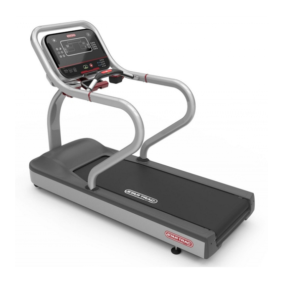
Star Trac 8TR Installation Instructions
Hide thumbs
Also See for 8TR:
- Owner's manual (52 pages) ,
- Service manual (63 pages) ,
- Assembly manual (14 pages)
Advertisement
Quick Links
8TR/8TR
I
I
x
nsTallaTIon
nsTRucTIons
1. R
eMove all paRts FRoM the box
Remove all the packaging material so the treadmill is ready for
assembly on the shipping crate platform. The raised front of the
shipping crate platform can be removed so that the treadmill can
roll out of the raised shipping platform rather than having to be
lifted out.
With a helper, roll the treadmill frame assembly motor end first
from the shipping crate platform and place it in the location where
it will be used. Make sure the unit is placed near a power outlet.
Caution: The motor shroud end of the frame assembly is
very heavy and two people may be needed to lift this end
when moving the frame assembly.
Document #620-8379 - Revision A
2. I
M
nstall the
ast
Remove the Neck Grommet and Motor Shroud Cap
and set aside. Be careful to not damaged data cable.
Remove the Motor Shroud then the Front Motor Shroud
Cap from the unit.
Insert mast as shown and fasten with (2) 5/16-18 x 3.0"
and (2) 5/16-18 x 1.0" socket head cap screws, (4) 5/16
washers and (4) lock washers. Do not fully tighten.
5. I
nstall hanDlebaR
Insert the handrail beauty rings onto the left and right handrails
as shown in step 4. Cut in ring must be oriented as shown above
facing mast. Prior to connecting display rail, slide both side rail
covers onto siderails.
Insert the left and right handrails into the display rail then thread
four (4) 1/4"x3/8" screws into the handrails . Tighten the handrail
hardware only after display rail is connected to both mast and
handrails.
For installation assistance or missing parts, please call Startrac Support at 1-800-503-1221
3. R
C
t
M
out
ables
hRough
ast
Route all cables up through the lower neck out out
of the top of the neck. Connect the following wires to
the MCB using the path shown under the elevation
motor:
715-3678 (DC Supply Power Cable) to J20
715-3682 (C-Safe Cable) to J10
715-3781 (Main Interface Ribbon Cable) to J1
4. M
D
R
ount the
Isplay
aIl
Install the neck beauty ring onto the top of the lower
neck as shown in detail.
Use a 1/4" Hex Allen key to install the four (4) M8x-
16mm button head cap screws and four (4) 5/16" wash-
ers as shown to secure the display rail to the lower
neck. Do not fully tighten and take care when routing
cables to avoid crimping or pinching.
6. s
s
R
F
eCuRe
IDe
aIls to
RaMe
Position the left and right handrails and use the
three (3) 5/16-18 x 1.0" socket head screws
and three (3) 5/16 washers to secure the hand-
rails to the frame. Start screws only.
Ensure that the neck, handrails, and display
rail are properly aligned then tighten the hard-
ware securing the handrails to the display rail,
the hardware securing the handrails to the
frame, and the lower neck to the frame to the
torque specifications below:
Lower Mast to Frame
5/16-18 x 3.0" Socket Head screws
240in-lbs / 27 N·m
Handrails to Frame
5/16-18 x 1.0" Socket Head screws
240in-lbs / 27 N·m
Handrails to display rail
1/4"x3/8" Button Head Socket screws
35in-lbs / 4.0 N·m
Advertisement

Summary of Contents for Star Trac 8TR
- Page 1 8TR/8TR nsTallaTIon nsTRucTIons 2. I 3. R nstall the ables hRough 4. M ount the Isplay Remove the Neck Grommet and Motor Shroud Cap Route all cables up through the lower neck out out Install the neck beauty ring onto the top of the lower and set aside.
- Page 2 7. I nstall otoR hRouD 8. R eInstall hRouD 9. v Reinstall Motor Shroud Cap and Neck Grommet as alIDate sseMbly Reinstall Front Motor Shroud Cap then fasten Mo- shown Frame assembly is complete. Prior to mounting con- tor Shroud and Side Bed Covers with (6) #10 Truss sole, verify console rail is secure and all mast screws Head screws.


Need help?
Do you have a question about the 8TR and is the answer not in the manual?
Questions and answers