Advertisement
Quick Links
Setup INSTRUCTIONS for
1. LOOP OUTPUT. Place the amplifier in a suitable position. It must not be covered.
Connection loop wires must be twisted. Normally single turn loops should be used, but two
turns loops give better result especially in smaller areas. Use a twin cable for trial purpose.
Select according to table below:
A
r
e
a
m
2
P
n i
-
n
o
1
t -
u
1
0
0
1 -
7
0
1
&
2
>
=
3
m
7
5
1 -
0
0
1
&
3
>
=
3
m
5
0
7 -
5
1
&
4
1 (
5 .
m
3
5
5 -
0
1
&
5
0 (
7 .
5
m
<
=
3
5
1
&
6
- -
- -
Loop current adjustment is done with 3 dB steps at the connector. Finer adjustment can be
made (normally not needed) with the trimmer marked "LOOP ADJ" at the printed circuit
board (fig 4, page2).
UNIVOX DLS-380 fulfils the International standards for Loop Systems up to 170m2
(squared loop, 1.2 m above the loop level). Reinforced concrete and other metallic objects
can reduce covered area strongly. The installation is not completed until the field
strength is verified according to international regulations (IEC 60118-4). For correct
measurement use FSM, field strength meter, together with the standardized artificial
speech for correct result.
2. TONE SIGNALING & DOORBELLS :
All connections except Fig 2D generates a signal, rich of harmonics through the loop.
2A. Door signal from existing system, 5-24VAC/DC. For DC operation connect + to pin 8.
The tone signalling output from a UNILUX 75F can be connected to this input:
connect 75F pins 13&14 to DLS-380 pins 8 and 9 respectively.
2B. Door and/or telephone bell with current supplied from the 380. 12V AC max. 1.6A.
2C. Tone signalling by closing contacts, pins 7&8 are strapped.
2D. Voltage outputs, 12V AC, max. 1.6A, no tone signalling via the loop.
3. INPUTS/OUTPUTS:
Potentiometer "In Adj" sets the input sensitivity. It is factory set to 50mV. There is
normally no need for adjustments because of the Dual Action AGC-circuitry.
IN1/IN2 = 7mV-10V/330Ohm, standard (uncut resistor). 150kOhm with cut resistor.
IN3 = 7mV-10V/100kOhm. Stereo input. Phantom Voltage matches all UniVox micro-
phones. A 50/100 Volts-line needs a separate transformer close to the UNIVOX DLS-380.
Auto Mute function (noise gate). If input signal is below AGC-knee level, (AGC-LED is
off) the amplifier mutes after 10 seconds. This reduce the risk of magnetic self oscillation
when the AGC circuitry slowly increases the gain. Disable this function by removing the
jumper Auto mute if there is a risk for quiet parts to be muted unnecessarily.
Note: When using high impedance signal (not recommended) into IN1 or IN2, the respec-
tive resistors marked IN1/IN2 on the Printed Circuit Board must be cut. Normally not
necessarily
Input 3 = IN3 on 7-pin DIN-connector on the right hand side. This connector also includes
the line output 0dB and a small power supply output. Please see Fig. 3B. The microphone
13A can be used with the TV-loudspeaker if a Scart connector is missing.
Note: No unconnected wire is permitted. The signal wires must be kept as far as possible
from the loop cable. Avoid parallel installations at distances of less than 200mm. Crosso-
vers are permitted.
4. STARTING UP: Connect UNIVOX DLS-380 to the mains outlet ("ON" LED lights
up). Please note that the amplifier is designed to be continuously powered. This actually
increases the apparatus lifetime. The stand-by power consumption is very low.
The LED marked "AGC" indicates when the input signal is high enough.
The LED marked "LOOP" indicates when there is current floating (sound in the Hearing
Instrument at T-position) in the loop.
A corresponding jumper inside the amplifier activates the AGC & LOOP Led. (Fig 4).
Check the frequency response and field strength according to the UNIVOX way to
fulfil the BS 6083 & international standard IEC 60118-4.
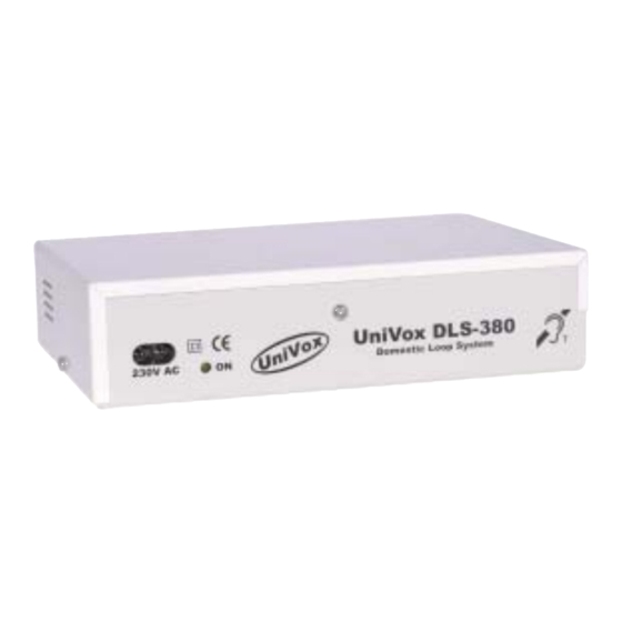
UNIVOX DLS-380
r
n
2
t -
u
r
n
L
e
v
l e
2
m
- -
- -
0
d
B
m
2
- -
- -
3 -
d
B
m
) 2
>
=
2
x
1
5 .
m
m
2
6 -
d
B
m
) 2
2
x
1
5 .
m
m
2
9 -
d
B
2
x
1
5 .
m
m
2
1 -
2
d
B
2004-01-20
E-mail: info@edin.se
Site:
www.edin.se
(With loop
beep signal)
(With loop
beep signal)
(With loop beep signal)
(Without loop beep
signal)
0 dB
OUT
LOOP
Door Bell
12V AC
Max. 1.6A
7
8 9 10
12V AC
Max. 1.6A
IN2
IN1
12V DC
7
6
MAX 30mA
1
Left.
3
IN3/
Mic & Scart
Right
4
2
WARNING!
LIVE TERMINALS ENCLOSED.
Always remove the power cord cable
before opening the amplifier!
Fig.1
Fig.2A
Fig.2B
Fig.2C
Fig.2D
Fig.3A
Fig.3B
Advertisement

Related Manuals for Univox DLS-380


Summary of Contents for Univox DLS-380
- Page 1 IN1/IN2 = 7mV-10V/330Ohm, standard (uncut resistor). 150kOhm with cut resistor. IN3 = 7mV-10V/100kOhm. Stereo input. Phantom Voltage matches all UniVox micro- phones. A 50/100 Volts-line needs a separate transformer close to the UNIVOX DLS-380. Auto Mute function (noise gate). If input signal is below AGC-knee level, (AGC-LED is off) the amplifier mutes after 10 seconds.
- Page 2 For questions and information please contact: WARNING! LIVE TERMINALS ENCLOSED. Always Field Strength Meter, remove the power cord FSM. Instrument for cable before opening the noise, freq.response, amplifier! fieldstrength of loop amplifier systems according to IEC-60118-4 2004-01-20. Z:\Products Public\Loop Amplifiers - system\DLS-380\English\Service\DLS-380_IgGbV1.PMD...
Need help?
Do you have a question about the DLS-380 and is the answer not in the manual?
Questions and answers