
Related Manuals for Univox PLS-X1


Summary of Contents for Univox PLS-X1
- Page 1 Univox® PLS-X1, X3, X5 Induction Loop Drivers Installation Guide Univox® PLS-X1 Part No 217100 Univox® PLS-X3 Part No 217300 Univox® PLS-X5 Part No 217500...
-
Page 2: Table Of Contents
Content Introduction ........................4 Package contents ......................4 Connections and controls ..................... 5 1. Input level control ..................... 6 2. Input level LEDs....................6 3-4. Parametric MLC ....................6 5. System Diagnostics .................... 7 6. Loop Current Control ..................7 7. - Page 3 Prepare installation .....................14 Planning ........................14 Tools required......................14 Loop cable ......................14 Placement of the driver ..................15 Placement of the microphones ................15 Maximum recommended segment size (to comply with IEC 60118-4) ...15 Installation ........................16 Start-up procedure ......................16 Input connection and adjustments ................16 Output connection and adjustments ...............17 Metal Loss Correction frequency setting ..............18 MLC function in maximum position ................18...
-
Page 4: Introduction
Our Engineering Simplicity philosophy is evident in the functionality and user-friendliness for each model. The three models in the series, PLS-X1, PLS-X3 and PLS-X5 are identical with the exception of output power. Each model offers three inputs, two programmable, including a 100V line setting, a self-test mode, loop- and speaker amplifier monitor. -
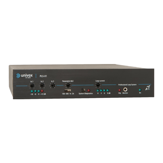
Page 5: Connections And Controls
8. 9. Input 3 Input 2 Input 1 Out Pre PUSH In Pow www.univox.eu Monitor 1. Input level control (Input 1-3) 16. Remote output monitor connector (screw 5+6) 2. Input level LEDs 17. Monitor volume control 3. Parametric MLC control 18. -
Page 6: Input Level Control
Explanation Note Univox PLS-X series is operational only if a loop cable is connected to the driver. Otherwise, the Peak indicator is lit constantly as a warning. All controls are regulated with a small screwdriver. 1. Input level control (In1-In3) Each input can be set to correct input by appropriate single-turn potentiometer located on the front panel. -
Page 7: System Diagnostics
5. System diagnostics Univox PLS-X series has a built-in system test. We recommend that this feature is used periodically, at least monthly, to check the integrity of the loop driver, its inputs and the loop condition. To access the system diagnostics mode, set the switch on the front panel to the right. -
Page 8: Voltage Clipping/Peak Led
Note In some cases metal reinforcement can actually reduce the voltage requirement. 9. Loop monitor/headphones socket Univox PLS-X series has a powerful speaker amplifier and a 3.5mm headphone socket ® built-in. The headphone socket is on the front panel, the speaker connectors (13) and volume control (17) are placed in the rear panel. -
Page 9: Loop Terminals
The voltage rating of the supply is dependent on the model. Only Univox approved power supplies correctly rated for the loop driver model should be used. The use of incorrectly rated, or third party power supplies will invalidate your 5 year warranty. -
Page 10: Remote Output Monitor Connector (Screw 5+6)
16. Remote output monitor connector (screw 5+6) A LED connected to this terminal will mirror the operation of the 0dB output current Level LED on the front panel, thus allowing the monitoring of the presence of output current in a more convenient location. -
Page 11: Input 3
20. Input 3 Input 3 Input 3 is an unbalanced line input. The sensitivity is adjusted using the control on the front panel. The source may be connected using the RCA connector (L/R) or the Phoenix screw terminal, but can't be used simultaneously. If the RCA input is used: Mono signals are connected through R or L and the earth connection. -
Page 12: Override On/Off Dip Switch 4
Note The DIP switches should be set in the appropriate position before connecting the input signal to avoid causing damage to the input. 24. Override On/Off (DIP switch 4) Input 2 With the DIP switch in ‘down’ position, Input 2 is set as the Priority Input. In this case, when a signal is detected, all other inputs will be suppressed. -
Page 13: Line/Mic Dip Switch 2 + 3
27. Line/Mic (DIP switch 2+3) The switch is used to alter the sensitivity of the XLR input for line and microphone. With the 2 DIP switches in the ‘down’ position, Input 1 is set to Line sensitivity. With the 2 DIP switches in the ‘up’ position, Input 1 is set to Mic sensitivity. For sensitivity levels, see Technical Specification on page 22-23. -
Page 14: Prepare Installation
Please refer to www.univox.eu/planning Use Univox Loop Designer (ULD), a free, web-based project planning and design tool that quickly and accurately assists in the design of loop systems. -
Page 15: Placement Of The Driver
Placement of the driver The Univox PLS-X loop drivers will not generate much excessive heat and can be mounted in 19" racks on top of or below other rack components (check that these don’t generate excessive heat), on a wall or another flat surface. In a rack system it is often practical to attach the external power supply to the supporting metallic construction using straps. -
Page 16: Installation
Installation Start-up procedure 1. Disconnect all input and output connections. 2. Each loop must be securely isolated (particularly to safety-ground and other loop connections). Verify the resistance of each loop (approximately 1-3 Ohm). 3. Set all level controls to minimum setting: •... -
Page 17: Output Connection And Adjustments
Note 1 To quickly set up the field strength for a real program source, a PPM instrument is helpful. The Univox Listener has a calibrated level indicator that quickly finds the highest peak. Note 2 When adjusting the field strength peaks, -2dB field strength works best, due to different dynamic headrooms in hearing aids. -
Page 18: Metal Loss Correction Frequency Setting
A guide how to commission a loop system to the IEC performance standard, can be found in the user guide for the Univox FSM 2.0 field strength meter and in the Univox® Certificate of Conformity. These documents are also available on www.univox.eu/certify. -
Page 19: Default Settings
Note To listen to the sound quality, use high quality headphones with the FSM 2.0 or Univox ® Listener loop receiver. The ‘Monitor’ Output socket is a direct reflection of the loop signal current (volume control on rear panel). The sound quality can be easily assessed at this point in the audio chain aiding set up and problem solving. -
Page 20: Trouble Shooting
Trouble shooting Symptom Possible cause Solution General malfunction Check the system with the start-up procedure. See page 10. Power LED is off Power supply not connected Connect power supply correctly Power supply faulty Replace power supply Input and output LEDs System Diagnostics turned on Turn System Diagnostics off flash on and off... - Page 21 Symptom Possible cause Solution Intelligibility of sound Low frequency masking Turn speech enhancement filter on from microphone is poor Poor microphone user Instruct user/reduce speaking distance techniques Microphone connected, Phantom power not turned on Turn phantom power on input LEDs are off Input level too low Increase input level/reduce speaking distance...
-
Page 22: Technical Specification
Technical Specification Audio Input 1 Connection Type: Balanced XLR (socket) Level: Switchable between Line (DIP switches 2 and 3 ‘down’ and Mic (DIP switches 2 and 3 ‘up’) Line sensitivity range: 40mV-2.6V (-25.7dBu to 10.5dBu) adjustable by control on front panel Mic sensitivity range: 2.5mV-160mV (-50dBu to -14dBu) adjustable by control on front panel... -
Page 23: In Pow Amp
Use the two outer connections for a single turn loop (see page 17). The two inner connections (center) are used as a shorting bar for configuring a 2-turn loop with twin core cable (see page 17) PLS-X1 PLS-X3 PLS-X5 Max Voltage... -
Page 24: Safety
Only use the power adapter supplied with the unit. If the power adapter or cable is damaged, replace with a genuine Univox part. Power adapter must be connected to a mains outlet close to the amplifier and easily accessible. -
Page 25: Maintenance And Care
Service Report Form which must be completed and returned with the product. Technical data For additional information, please refer to product data sheet/brochure and CE certificate which can be downloaded from www.univox.eu/products. If required other technical documents can be ordered from support@edin.se. Environment To prevent possible harm to the environment and human health, at the end of serviceable life of the product, please dispose of responsibly by following statutory Disposal Regulations. -
Page 26: Measuring Devices
Measuring and control devices Univox® FSM 2.0, Field Strength Meter Instrument for the professional measurement and certification of loop systems in accordance with IEC 60118-4. Univox® Listener Loop receiver for fast and simple check of the sound quality and basic level control of the loop. -
Page 27: Notes
Notes _______________________________________________________________ _______________________________________________________________ _______________________________________________________________ _______________________________________________________________ _______________________________________________________________ _______________________________________________________________ _______________________________________________________________ _______________________________________________________________ _______________________________________________________________ _______________________________________________________________ _______________________________________________________________ _______________________________________________________________ _______________________________________________________________ _______________________________________________________________ _______________________________________________________________ _______________________________________________________________ _______________________________________________________________ _______________________________________________________________ _______________________________________________________________ _______________________________________________________________... - Page 28 Distributor Univox by edin, the world's leading authority and producer of high quality hearing loop systems created the first true loop amplifier in 1969. With our strong emphasis on research and development, we have continued to innovate to deliver more firsts in the industry, constantly improving the performance of our products and service for hard of hearing communities worldwide.
Need help?
Do you have a question about the PLS-X1 and is the answer not in the manual?
Questions and answers