Advertisement
Quick Links
Download this manual
See also:
Installation Manual
Commissioning
The process for commissioning a loop system to the IEC performance
standard, IEC 60118-4, can be found in the user guide for the Univox FSM
2.0 field strength meter, on the Univox
equipment Logbook, if supplied. These documents are also available on our
websites.
1. Set the loop current to minimum by setting the control fully anti-
clockwise.
2. Connect the test signal source to the appropriate input.
3. Adjust the input level to the point at which the red, +12 dB LED flickers
sporadically in sympathy with the highest signal peaks. Where a 1
kHz sine wave signal is used the level should be adjusted to 0 dB LED
indication.
4. Follow the commissioning process.
General Notes
To listen to the sound quality, use high quality headphones with the FSM 2.0
or Univox
Listener loop receiver.
®
The 'Monitor' Output socket is a direct reflection of the loop signal current
(volume control on rear panel). The sound quality can be easily assessed at
this point in the audio chain aiding set up and problem solving.
When operating at maximum output on some loop types the automatic limit
protection circuit may cut programme peaks. To rectify, reduce the loop
current accordingly.
To adjust the frequency response of the system use the 'Parametric MLC'.
The degree of compensation is adjusted with the potentiometer and the start
or break frequency is determined by the 4 position switch marked: 100 Hz,
500 Hz, 1 kHz, 2 kHz. Start with the break frequency set to 2 kHz and adjust
the level. If this is not sufficient, move to the next lower frequency and repeat
as required.
Bo Edin AB
+46 (0)8 767 18 18
Sweden and International
info@edin.se
Sales
www.univox.eu
Certificate of Conformity or in the
®
UnivoxAudio
+44 (0)1707 339216
Ltd.
writeto@univoxaudio.co.uk
UK Sales
www.univoxaudio.co.uk
Quick Installation Guide
Univox® PLS-X1, X3 and X5
Induction Loop Drivers
Package contents
The X series package contains the following components:
•
Loop driver
•
DC Power Supply
•
Power cable
•
Three pieces of phoenix screw terminals
•
Four pieces of rubber feet
•
T Sign
•
Rack mounting plate with 8 screws
•
DC Power supply mounting plate with 4 screws (including two
pieces of 3M Scotchmate that can be used to fix the power supply
to the mounting plate)
•
Measuring protocol/certificate
•
Quick Installation Guide
For Complete Installation Guide please download
from www.univox.eu or use QR code.
Advertisement

Related Manuals for Univox PLS-X3


Summary of Contents for Univox PLS-X3
- Page 1 Commissioning The process for commissioning a loop system to the IEC performance standard, IEC 60118-4, can be found in the user guide for the Univox FSM 2.0 field strength meter, on the Univox Certificate of Conformity or in the ®...
-
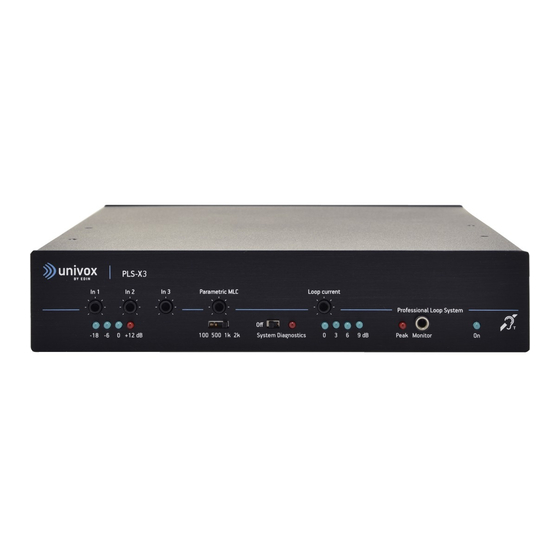
Page 2: Connections And Controls
5. Adjust the loop current. Depending on the adjusted current level, 1, 2, 3 or 4 out put current LEDs will blink in unison. In Pow www.univox.eu Monitor 6. Set the current to achieve a field strength of the peaks to approximately -3 dB in the center of the loop.
Need help?
Do you have a question about the PLS-X3 and is the answer not in the manual?
Questions and answers