Advertisement
Quick Links
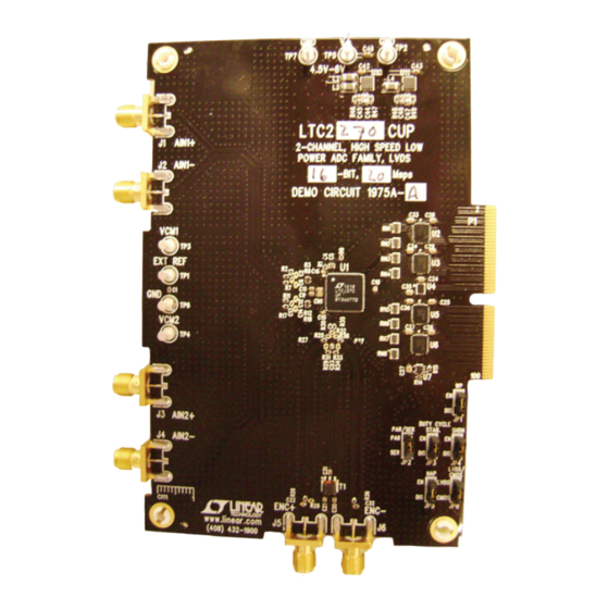
DESCRIPTION
Demonstration circuit 1975A supports the
speed, high dynamic range ADC. It was specially designed
for applications that require differential DC inputs. DC1975
supports the LTC2270 in CMOS output mode.
The circuitry on the analog inputs is optimized for ana-
log input frequencies from DC to 70MHz. Refer to the
DC1975 VARIANTS
DC1975 VARIANTS
1975A
PERFORMANCE SUMMARY
PARAMETER
Supply Voltage: DC1975A
Analog Input Range
Logic Input Voltages
Sampling Frequency (Convert Clock
Frequency)
Convert Clock Level
Convert Clock Level
Resolution
Input Frequency Range
LTC
2270
high
®
ADC PART NUMBER
LTC2270
Specifications are at T
CONDITIONS
Depending on Sampling Rate and the A/D Converter
Provided, This Supply Must Provide Up to 300mA
Depending on SENSE Pin Voltage
Minimum Logic High
Maximum Logic Low
Single-Ended Encode Mode (ENC– Tied to GND)
Differential Encode Mode (ENC– Not Tied to GND)
DEMO MANUAL DC1975A
16-Bit, 20Msps Dual ADC
data sheet for proper input networks for different input
frequencies.
Design files for this circuit board are available at
http://www.linear.com/demo
L, LT, LTC, LTM, Linear Technology and the Linear logo are registered trademarks and PScope
and QuikEval are trademarks of Linear Technology Corporation. All other trademarks are the
property of their respective owners.
RESOLUTION
MAXIMUM SAMPLE RATE
16-Bit
= 25°C
A
LTC2270
INPUT FREQUENCY
20Msps
DC to 70MHz
MIN
TYP
MAX
4.5
6
1
2.1
1.3
0.6
1
20
0
3.6
0.2
3.6
16
DC
70
UNITS
V
V
P-P
V
V
Msps
V
V
MHz
dc1975fa
1
Advertisement

Related Manuals for Linear Technology LTC2270


Summary of Contents for Linear Technology LTC2270
- Page 1 The circuitry on the analog inputs is optimized for ana- L, LT, LTC, LTM, Linear Technology and the Linear logo are registered trademarks and PScope log input frequencies from DC to 70MHz. Refer to the and QuikEval are trademarks of Linear Technology Corporation. All other trademarks are the property of their respective owners.
-
Page 2: Quick Start Procedure
QUICK START PROCEDURE DC1975A is easy to set up to evaluate the performance of SETUP the LTC2270 A/D converter. Refer to Figure 1 for proper The DC890 USB demonstration circuit was supplied with measurement equipment setup and follow the procedure the DC1975 demonstration circuit. -
Page 3: Hardware Setup
JP4 SHDN: In parallel programming mode enables or proper voltages for the ADC and buffers. The voltage range disables LTC2270. In serial programming mode, pull up for this turret is 4.5V up to 6V. to VDD. (Default: Enable or pull up) - Page 4 DEMO MANUAL DC1975A APPLYING POWER & SIGNALS TO THE DC1975 DEMONSTRATION CIRCUIT If a DC890 is used to acquire data from the DC1975, the The DC890 data collection board is powered by the USB DC890 must FIRST be connected to a powered USB port cable and does require an external power supply when or provided an external 6V to 9V BEFORE applying 4.5V to collecting data from an LVDS demo board.
- Page 5 13dBm. When analog inputs. using a sinusoidal signal generator, a squaring circuit can be used. Linear Technology also provides DC1075A, An internally generated conversion clock output is a demo board that divides a high frequency sine wave by available on P1, which could be collected via a logic...
- Page 6 (see Figure 2). PScope has the ability to program the DC1975 board serially through the DC890. There are several options available in the LTC2270 family that are only available through serially programming. PScope allows all of these features to be tested.
- Page 7 4.5mA: LVDS output driver current This menu allows any of the options available for the Internal Termination: Enables LVDS internal termination. LTC2270 family to be programmed serially. The LTC2270 (Not supported by DC1975A) family has the following options: Off (default): Disables internal termination...
-
Page 8: Parts List
DEMO MANUAL DC1975A SOFTWARE Test Pattern: Selects digital output test patterns Randomizer: Enables data output randomizer Off (default): ADC data presented at output Off (default): Disables data output randomizer All Out =1: All digital outputs are 1 On: Enables data output randomizer All Out = 0: All digital outputs are 0 Two’s complement: Enables two’s complement mode Checkerboard: OF and D13-D0 alternate between... - Page 9 VISHAY, CRCW0603330KFKEA TP1-TP7 TP, TURRETS, 0.094" MILL-MAX, 2501-2-00-80-00-00-07-0 XFMR, 1:1, TRANS-MABA-007159 MACOM, MABA-007159-000000 IC, LTC2270CUP, QFN64UP-9×9 LINEAR TECHNOLOGY, LTC2270CUP U2, U3, U5, U6 IC, 8-BIT DUAL VOLTAGE SUPPLY FAIRCHILD SEMI., FXLH42245MPX TRANSLATOR, MICROPAK-10 IC, 2-BIT DUAL VOLTAGE SUPPLY FAIRCHILD SEMI., FXL2T245L10X...
-
Page 10: Schematic Diagram
DEMO MANUAL DC1975A SCHEMATIC DIAGRAM dc1975fa... - Page 11 Information furnished by Linear Technology Corporation is believed to be accurate and reliable. However, no responsibility is assumed for its use. Linear Technology Corporation makes no representa- tion that the interconnection of its circuits as described herein will not infringe on existing patent rights.
- Page 12 Linear Technology Corporation (LTC) provides the enclosed product(s) under the following AS IS conditions: This demonstration board (DEMO BOARD) kit being sold or provided by Linear Technology is intended for use for ENGINEERING DEVELOPMENT OR EVALUATION PURPOSES ONLY and is not provided by LTC for commercial use. As such, the DEMO BOARD herein may not be complete in terms of required design-, marketing-, and/or manufacturing-related protective considerations, including but not limited to product safety measures typically found in finished commercial goods.
Need help?
Do you have a question about the LTC2270 and is the answer not in the manual?
Questions and answers