Advertisement
LTC2182, LTC2181, LTC2180, LTC2188, LTC2145-14/-12,
LTC2144-14/-12, LTC2143-14/-12, LTC2142-14/-12, LTC2141-14/-12,
DESCRIPTION
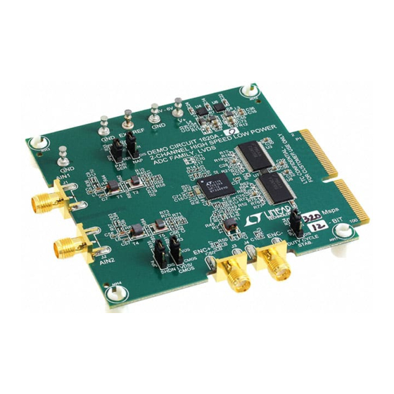
Demonstration circuit 1620A supports a family of
16-/14-/12-bit, 20Msps to 125Msps ADCs. Each assembly
features one of the following devices: LTC
LTC2183, LTC2182, LTC2181, LTC2180, LTC2188,
LTC2145-14, LTC2144-14, LTC2143-14, LTC2142-14,
LTC2141-14, LTC2140-14, LTC2145-12, LTC2144-12,
LTC2143-12, LTC2142-12, LTC2141-12, or LTC2140-12,
LTC2270 high speed, high dynamic range ADCs.
Demonstration circuit 1620A supports the LTC2185/
LTC2145 family DDR LVDS output mode.
Table 1. DC1620 Variants
DC1620 VARIANTS
1620A-A
1620A-B
1620A-C
1620A-D
1620A-E
1620A-F
1620A-G
1620A-H
1620A-I
1620A-J
1620A-K
1620A-L
1620A-M
1620A-N
1620A-O
1620A-P
1620A-Q
1620A-R
1620A-S
1620A-T
Arrow.com.
Downloaded from
LTC2140-14/-12, LTC2270: 16-/14-/12-Bit,
®
2185, LTC2184,
ADC PART NUMBER
RESOLUTION
LTC2185
LTC2184
LTC2183
LTC2182
LTC2181
LTC2180
LTC2145-14
LTC2144-14
LTC2143-14
LTC2142-14
LTC2141-14
LTC2140-14
LTC2145-12
LTC2144-12
LTC2143-12
LTC2142-12
LTC2141-12
LTC2140-12
LTC2188
LTC2270
DEMO MANUAL DC1620A
LTC2185, LTC2184, LTC2183,
20Msps to 125Msps Dual ADCs
The versions of the 1620A demo board supporting the
LTC2185 and LTC2145 series of A/D converters are listed
in Table 1. Depending on the required resolution and
sample rate, the DC1620A is supplied with the appropri-
ate ADC. The circuitry on the analog inputs is optimized
for analog input frequencies from 5MHz to 70MHz. Refer
to the data sheet for proper input networks for different
input frequencies.
Design files for this circuit board are available at
http://www.linear.com/demo
L, LT, LTC, LTM, Linear Technology and the Linear logo are registered trademarks and
QuikEval and PScope are trademarks of Linear Technology Corporation. All other trademarks are
the property of their respective owners.
MAXIMUM SAMPLE RATE
16-Bit
125Msps
16-Bit
105Msps
16-Bit
80Msps
16-Bit
65Msps
16-Bit
40Msps
16-Bit
25Msps
14-Bit
125Msps
14-Bit
105Msps
14-Bit
80Msps
14-Bit
65Msps
14-Bit
40Msps
14-Bit
25Msps
12-Bit
125Msps
12-Bit
105Msps
12-Bit
80Msps
12-Bit
65Msps
12-Bit
40Msps
12-Bit
25Msps
16-Bit
20Msps
16-Bit
20Msps
INPUT FREQUENCY
5MHz to 140MHz
5MHz to 140MHz
5MHz to 140MHz
5MHz to 140MHz
5MHz to 140MHz
5MHz to 140MHz
5MHz to 140MHz
5MHz to 140MHz
5MHz to 140MHz
5MHz to 140MHz
5MHz to 140MHz
5MHz to 140MHz
5MHz to 140MHz
5MHz to 140MHz
5MHz to 140MHz
5MHz to 140MHz
5MHz to 140MHz
5MHz to 140MHz
5MHz to 140MHz
5MHz to 140MHz
dc1620afb
1
Advertisement
Table of Contents

Related Manuals for Linear Technology DC1620A


Summary of Contents for Linear Technology DC1620A
- Page 1 LTC2145 family DDR LVDS output mode. L, LT, LTC, LTM, Linear Technology and the Linear logo are registered trademarks and QuikEval and PScope are trademarks of Linear Technology Corporation. All other trademarks are the property of their respective owners.
-
Page 2: Performance Summary
Demonstration Circuit was supplied with the DC1620A demonstration circuit, If a DC890 is used to acquire data from the DC1620A, the follow the DC890 Quick Start Guide to install the required DC890 must first be connected to a powered USB port software and for connecting the DC890 to the DC1620A or provided an external 6V to 9V before applying +4.5V... - Page 3 SNR. In As a default, the DC1620A is populated to have a single- the case of the DC1620A a bandpass filter used for the clock ended input. should be used prior to the DC1075 clock divider board.
- Page 4 In the case of the DC1620A a bandpass filter used for the clock should be used prior to the DC1075. Data sheet FFT plots are taken...
- Page 5 • Normal (Default) – Entire ADC is powered, and active • Full Rate – Full rate CMOS output mode (This mode is • Ch1 Normal Ch2 Nap – Channel 1 remains active while not supported by the DC1620A) channel 2 is put into nap mode dc1620afb Arrow.com.
-
Page 6: Parts List
• Double CMOS – double data rate CMOS output mode • On – Enables alternate bit polarity (before enabling ABP , (This mode is not supported by the DC1620A) be sure the part is in offset binary mode) Test Pattern: Selects Digital output test patterns. - Page 7 DEMO MANUAL DC1620A PARTS LIST ITEM REFERENCE PART DESCRIPTION MANUFACTURER/PART NUMBER RES ARRAY, 33Ω VISHAY CRA04SS08333R0JTD R1, R2, R60, R74 RES, 0402 49.9Ω 1% 1/16W YAGEO RC0402FR-0749R9L R4, R5, R49-R52, R82, R83-R85 RES, 0402 OPTION OPTION RES, 0402 10k 5% 1/16W...
-
Page 8: Schematic Diagram
DEMO MANUAL DC1620A SCHEMATIC DIAGRAM dc1620afb Arrow.com. Arrow.com. Arrow.com. Arrow.com. Arrow.com. Arrow.com. Arrow.com. Arrow.com. Downloaded from Downloaded from Downloaded from Downloaded from Downloaded from Downloaded from Downloaded from Downloaded from... - Page 9 Information furnished by Linear Technology Corporation is believed to be accurate and reliable. However, no responsibility is assumed for its use. Linear Technology Corporation makes no representa- tion that the interconnection of its circuits as described herein will not infringe on existing patent rights.
- Page 10 Linear Technology Corporation (LTC) provides the enclosed product(s) under the following AS IS conditions: This demonstration board (DEMO BOARD) kit being sold or provided by Linear Technology is intended for use for ENGINEERING DEVELOPMENT OR EVALUATION PURPOSES ONLY and is not provided by LTC for commercial use. As such, the DEMO BOARD herein may not be complete in terms of required design-, marketing-, and/or manufacturing-related protective considerations, including but not limited to product safety measures typically found in finished commercial goods.
Need help?
Do you have a question about the DC1620A and is the answer not in the manual?
Questions and answers