Table of Contents
Advertisement
Quick Links
QUICK START GUIDE FOR DEMONSTRATION CIRCUIT 1278
DESCRIPTION
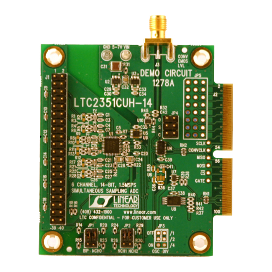
Demonstration circuit 1278 features the LTC2351-14
6-channel, 14-Bit, simultaneous sampling ADC. Total
throughput is 1.5MSPS; 250KSPS per channel, with a
typical channel-to-channel aperture skew of 200ps.
The board is designed to be used with the DC890B
Fast DAACS data collection board to show the AC
performance of the LTC2351-14. Alternatively, the
QUICK START PROCEDURE
BASIC CONNECTIONS
Connect DC1278 to a DC890B USB High Speed Data
Collection Board using connector J2. Connect
DC890B to a host PC with a standard USB A/B cable.
Apply 5-7V DC to the VIN and GND terminals. Apply a
25MHz 3.3Vp-p sine wave or square wave to connec-
6-CHANNEL, 14-BIT, 1.5MSPS SIMULTANEOUS SAMPLING ADC
board can be directly connected to an application to
evaluate the ADC's performance.
Design files for this circuit board are available. Call
the LTC factory.
LTC is a trademark of Linear Technology Corporation
tor J3. Note that J3 has a 50 ohm termination resistor
to ground. CH0-CH5 are provided through connector
J1 (See schematic for details.). Run the QuickEval II
(Pscope.exe) evaluation software supplied with
DC890 or download it from www.linear.com/software.
LTC2351-14
1
Advertisement
Table of Contents

Related Manuals for Linear Technology LTC2351-14


Summary of Contents for Linear Technology LTC2351-14
- Page 1 200ps. the LTC factory. The board is designed to be used with the DC890B LTC is a trademark of Linear Technology Corporation Fast DAACS data collection board to show the AC performance of the LTC2351-14. Alternatively, the...
- Page 2 QUICK START GUIDE FOR DEMONSTRATION CIRCUIT 1278 6-CHANNEL, 14-BIT, 1.5MSPS SIMULTANEOUS SAMPLING ADC Figure 1. CONNECTION DIAGRAM Master clock at 98x conversion rate, 3.3Vpp Sine or Square wave (See 5-7VDC Supply Hardware Setup Section) 40 pin Analog Signal Connector To DC890B (Refer to Schematic) Controller...
- Page 3 QUICK START GUIDE FOR DEMONSTRATION CIRCUIT 1278 6-CHANNEL, 14-BIT, 1.5MSPS SIMULTANEOUS SAMPLING ADC Figure 2. SOFTWARE SCREENSHOT Figure 3. CONFIGURE MENUS...
- Page 4 QUICK START GUIDE FOR DEMONSTRATION CIRCUIT 1278 6-CHANNEL, 14-BIT, 1.5MSPS SIMULTANEOUS SAMPLING ADC SOFTWARE CONFIGURATION CONFIGURE SOFTWARE SCREEN CONFIGURE DEVICE The software interface is highly configurable and The Pscope software should automatically config- displays any combination of time domain data, fre- ure itself after detecting the demo board.
- Page 5 LTC2351-14 at maximum conversion rate, apply pins. This can be used to either monitor signals a 25MHz signal to this input. with a logic analyzer or to drive the LTC2351-14 GROUNDING AND POWER CONNECTION directly from the customer’s test equipment or pro- totype circuitry.
- Page 6 QUICK START GUIDE FOR DEMONSTRATION CIRCUIT 1278 6-CHANNEL, 14-BIT, 1.5MSPS SIMULTANEOUS SAMPLING ADC...
- Page 7 QUICK START GUIDE FOR DEMONSTRATION CIRCUIT 1278 6-CHANNEL, 14-BIT, 1.5MSPS SIMULTANEOUS SAMPLING ADC...
Need help?
Do you have a question about the LTC2351-14 and is the answer not in the manual?
Questions and answers