Advertisement
Quick Links
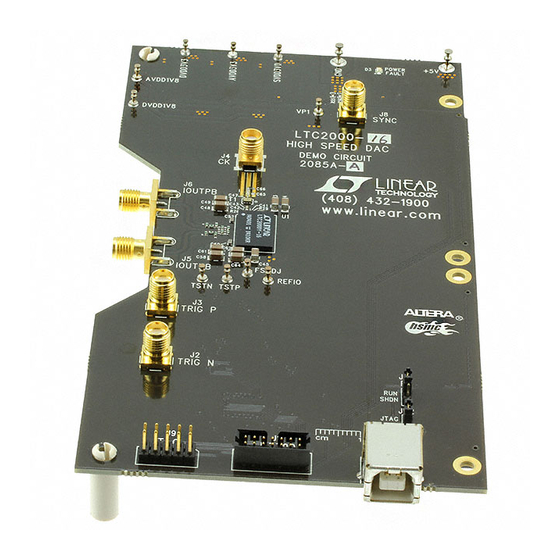
Description
Demonstration circuit 2085 supports the
LTC2000A, a high speed, high dynamic range family of
DACs. It was specially designed for applications that re-
quire differential DC coupled outputs. DC2085 supports
the complete family of the LTC2000 including 16, 14 and
11 bit parts. For all the variations see Table 1.
Table 1. DC2085 Variants
DC2085 VARIANTS
PART NUMBER
DC2085A-A
LTC2000-16
DC2085A-B
LTC2000-14
DC2085A-C
LTC2000-11
DC2085A-D
LTC2000A-16
DC2085A-E
LTC2000A-14
DC2085A-F
LTC2000A-11
performance summary
PARAMETER
Supply Voltage – DC2085
Sampling Frequency (Sample Clock Frequency)
Sample Clock Level (Single-Ended)
LVDS Inputs
16-, 14-, 11-Bit, 2.5Gsps to 2.7Gsps DACs
LTC
2000
and
®
RESOLUTION
16-Bit
14-Bit
11-Bit
16-Bit
14-Bit
11-Bit
Specifications are at T
CONDITIONS
This supply must provide up to 800mA
Use a 50Ω Source
Differential Input Voltage Range
Common Mode Voltage Range
DEMO MANUAL DC2085
LTC2000, LTC2000A
The circuitry on the analog outputs is optimized for analog
frequencies from DC-1.08GHz.
Design files for this circuit board are available at
http://www.linear.com/demo/DC2085
L, LT, LTC, LTM, Linear Technology and the Linear logo are registered trademarks of Linear
Technology Corporation. All other trademarks are the property of their respective owners.
MAXIMUM SAMPLE RATE
2.5Gsps
2.5Gsps
2.5Gsps
2.7Gsps
2.7Gsps
2.7Gsps
= 25°C
A
MIN
4.8
300
0
±0.2
0.4
OUTPUT FREQUENCY
DC-1000MHz
DC-1000MHz
DC-1000MHz
DC-1080MHz
DC-1080MHz
DC-1080MHz
TYP
MAX
UNITS
5.0
5.2
2500 or 2700
MHz
15
dBm
±0.6
1.8
dc2085afa
1
V
V
V
Advertisement

Related Manuals for Linear Technology DC2085


Summary of Contents for Linear Technology DC2085
- Page 1 LTC2000 including 16, 14 and L, LT, LTC, LTM, Linear Technology and the Linear logo are registered trademarks of Linear 11 bit parts. For all the variations see Table 1. Technology Corporation. All other trademarks are the property of their respective owners.
- Page 2 DEMO MANUAL DC2085 Quick start proceDure DC2085 is easy to set up to evaluate the performance of the Setup LTC2000. Refer to Figure 1 for proper measurement equip- The Altera Stratix IV GX FPGA Development Kit was ment set-up and follow the procedure below: supplied with the DC2085 demonstration circuit.
- Page 3 GND: Ground Connection. This demo board has only a single ground plane. This turret should be tied to the GND The DC2085 demonstration circuit should have the fol- terminal of the power supply being used. lowing jumper settings as default positions.
- Page 4 LTDACGen should report back that it is connected to the FPGA. See Figure 2: If a Stratix IV demo board is used to supply data to the DC2085, the two boards should first be bolted together Figure 2. LTDACGen Connected to FPGA dc2085afa...
- Page 5 FPGA to 50Ω per side. This allows the demo board to drive a 50Ω test the DC2085. For more information about how to use analyzer through a balun or other combiner. the LTDACGen software, refer to the help files that come with the software.
- Page 6 DEMO MANUAL DC2085 Quick start proceDure Figure 4. DC2085 Results. Close-In (Top) and wideband (Bottom) dc2085afa...
- Page 7 DEMO MANUAL DC2085 parts List ITEM REFERENCE PART DESCRIPTION MANUFACTURER/PART NUMBER Required Circuit Components C1, C25, C26, C29, C31, CAP., X7R, 0.1µF, 16V 10% 0402 AVX, 0402YC104KAT2A C32, C33, C34, C35, C36, C37, C71, C72 C2, C3, C8, C19 CAP., NPO, 0.01µF, 25V 5% 0603...
- Page 8 DEMO MANUAL DC2085 parts List ITEM REFERENCE PART DESCRIPTION MANUFACTURER/PART NUMBER L1, L2, L3, L4, L6, L7 FERRITE BEAD, 33Ω AT 100mHz, 1206 MURATA, BLM31PG330SN1L INDUCTOR, 2.2µH, 20% HIGH CURRENT, SMT VISHAY, IHLP2020BZER2R2M11 INDUCTOR, CERAMIC CHIP, 1nH, 5%, 0402 COILCRAFT, 0402CS-1N0XJLU FERRITE BEAD, 30Ω...
- Page 9 DEMO MANUAL DC2085 parts List ITEM REFERENCE PART DESCRIPTION MANUFACTURER/PART NUMBER U10, U11 I.C., LOW DROPOUT REGULATOR, 3×3mm, DFN LINEAR TECHNOLOGY, LT3080EDD#PBF I.C., 80V IDEAL DIODE, DFN-6L LINEAR TECHNOLOGY, LTC4359HDCB-#TRPBF XJP1, XJP2 SHUNT, 2mm SAMTEC, 2SN-BK-G CRYSTAL, 12.0 MHz, SMT ABRACON, ABMM2-12.000MHZ-E2-T...
- Page 10 Information furnished by Linear Technology Corporation is believed to be accurate and reliable. However, no responsibility is assumed for its use. Linear Technology Corporation makes no representa- tion that the interconnection of its circuits as described herein will not infringe on existing patent rights.
- Page 11 DEMO MANUAL DC2085 schematic Diagram dc2085afa...
- Page 12 DEMO MANUAL DC2085 schematic Diagram dc2085afa...
- Page 13 DEMO MANUAL DC2085 schematic Diagram dc2085afa...
- Page 14 Linear Technology Corporation (LTC) provides the enclosed product(s) under the following AS IS conditions: This demonstration board (DEMO BOARD) kit being sold or provided by Linear Technology is intended for use for ENGINEERING DEVELOPMENT OR EVALUATION PURPOSES ONLY and is not provided by LTC for commercial use. As such, the DEMO BOARD herein may not be complete in terms of required design-, marketing-, and/or manufacturing-related protective considerations, including but not limited to product safety measures typically found in finished commercial goods.
Need help?
Do you have a question about the DC2085 and is the answer not in the manual?
Questions and answers