LS Industrial Systems XGT Series User Manual
Programmable logic controller, xgb positioning module
Hide thumbs
Also See for XGT Series:
- User manual (223 pages) ,
- Manual (41 pages) ,
- User manual (103 pages)
Table of Contents
Advertisement
Quick Links
Right choice for ultimate yield
LSIS strives to maximize customers' profit in gratitude of choosing us for your partner.
Programmable Logic Controller
XGB Positioning Module
XGT Series
Read this manual carefully before
installing, wiring, operating, servicing
or inspecting this equipment.
Keep this manual within easy reach
for quick reference.
User's Manual
XBF-PD02A
http://eng.lsis.biz
Advertisement
Table of Contents

Related Manuals for LS Industrial Systems XGT Series


Summary of Contents for LS Industrial Systems XGT Series
- Page 1 Right choice for ultimate yield LSIS strives to maximize customers' profit in gratitude of choosing us for your partner. Programmable Logic Controller XGB Positioning Module XGT Series User’s Manual XBF-PD02A Read this manual carefully before installing, wiring, operating, servicing or inspecting this equipment.
- Page 2 Safety Instruction Before using the product … For your safety and effective operation, please read the safety instructions thoroughly before using the product. ► Safety Instructions should always be observed in order to prevent accident or risk with the safe and proper use the product.
- Page 3 Safety Instruction Safety Instructions for design process Warning Please install a protection circuit on the exterior of PLC so that the whole system may operate safely regardless of failures from external power or PLC. Any abnormal output or operation from PLC may cause serious problems to safety in whole system. Install protection units on the exterior of PLC like an interlock circuit that deals with opposite operations such as emergency stop, protection circuit, and forward/reverse rotation or install an interlock circuit that deals with high/low limit under its position controls.
- Page 4 Safety Instruction Safety Instructions for design process Caution I/O signal or communication line shall be wired at least 100mm away from a high-voltage cable or power line. Fail to follow this Safety Instructions on installation process Caution Use PLC only in the environment specified in PLC manual or general standard of data sheet.
- Page 5 Safety Instruction Safety Instructions for wiring process Warning Prior to wiring works, make sure that every power is turned off. If not, electric shock or damage on the product may be caused. After wiring process is done, make sure that terminal covers are installed properly before its use.
- Page 6 Safety Instruction Safety Instructions for test-operation and maintenance Warning Don’t touch the terminal when powered. Electric shock or abnormal operation may occur. Prior to cleaning or tightening the terminal screws, let all the external power off including PLC power. If not, electric shock or abnormal operation may occur. Don’t let the battery recharged, disassembled, heated, short or soldered.
- Page 7 Safety Instruction Safety Instructions for waste disposal Caution Product or battery waste shall be processed as industrial waste. The waste may discharge toxic materials or explode itself.
- Page 8 Revision History Revision History Version Date Remark Page V 1.0 ’10. 1 First Edition ※ The number of User’s manual is indicated right part of the back cover. ⓒ LS Industrial Systems Co., Ltd 2010 All Rights Reserved.
- Page 9 About User’s Manual About User’s Manual Thank you for purchasing PLC of LS Industrial System Co.,Ltd. Before use, make sure to carefully read and understand the User’s Manual about the functions, performances, installation and programming of the product you purchased in order for correct use and importantly, let the end user and maintenance administrator to be provided with the User’s Manual.
-
Page 10: Table Of Contents
◎ Contents ◎ Chapter 1 Overview ................1-1~1-9 1.1 Characteristics......................1-1 1.2 Purpose of Positioning Control ................1-2 1.3 Signal Flow of Positioning Module................1-3 1.3.1 Operating sequence ....................1-3 1.3.2 Flow of position signal ....................1-4 1.4 Function overview of positioning module..............1-5 1.4.1 Position Control ......................1-5 1.4.2 Interpolation Control ....................1-6 1.4.3 Speed Control......................1-9... - Page 11 3.2.2 Connection Example of Servo and Stepping Motor Drive Machine ......3-3 3.2.3 Encoder Input (DC 5V Voltage Output) Wiring Example..........3-13 3.2.4 Encoder Input (5V Line Driver Output) Wiring Example ..........3-14 Chapter 4 Positioning Parameter & Operation Data......4-1~4-24 4.1 Parameter & Operation data..................4-1 4.2 Basic Parameter ......................
- Page 12 6.1.1 Internal Memory Read....................6-1 6.1.2 Internal Memory Write....................6-2 6.2 Dedicated Commands ..................... 6-3 6.3 Use of Dedicated Command ................... 6-4 6.3.1 Homing start .......................6-4 6.3.2 Floating origin setting (Command : FLT)..............6-5 6.3.3 Direct start (Command : DST)..................6-6 6.3.4 Indirect start (Command : IST)..................6-7 6.3.5 Linear Interpolation (Command: LIN).................6-8 6.3.6 Circular Interpolation (Command: CIN)..............6-9 6.3.7 Simultaneous Start (Command : SST)..............6-10...
- Page 13 6.3.33 Operation State Reading (Command: SRD) ............6-39 Chapter 7 Function Block..............7-1~7-37 7.1 Common Issues of Function Block ................7-1 7.2 Function Block of Positioning Module ..............7-2 7.3 Function Block related to Module Information Read..........7-3 7.3.1 Operation Information Read (APM_CRD) ..............7-3 7.3.2 Operation State Bit Information Read (APM_SRD) ...........7-4 7.3.3 Encoder Value Read (APM_ENCRD) ................7-6 7.4 Parameter/Operation Data Teaching Function Block ..........
- Page 14 7.8.3 Position Assigned Speed Override (APM_PSO)............7-28 7.8.4 Position/Speed Switching Control (APM_PTV)............7-29 7.8.5 Speed/Position Switching Control (APM_VTP)............7-30 7.8.6 Start Step Number Change (APM_SNS) ..............7-31 7.8.7 Repeat Step No. Change (APM_SRS) ..............7-32 7.8.8 Current Position Change (APM_PRS)..............7-33 7.8.9 Encoder Value Preset (APM_EPRE) ...............7-34 7.9 Error Function blocks ....................
- Page 15 9.1.1 Homing method......................9-1 9.1.2 Parameters for Homing....................9-1 9.1.3 Origin Detection after DOG Off ..................9-2 9.1.4 Origin Detection after Deceleration when DOG On ...........9-4 9.1.5 Origin Detection by DOG ...................9-5 9.1.6 Origin Detection by Origin and Upper/Lower Limit ............9-6 9.1.7 Origin Detection by Upper/Lower Limit ..............9-7 9.2 Positioning Control ....................
- Page 16 9.6.1 Upper/Lower limit .....................9-90 9.6.2 M code ........................9-92 9.7 Data Modification Function ..................9-94 9.7.1 Teaching Array ......................9-94 9.7.2 Parameter Change from Program ................9-95 9.7.3 Data Change from Program..................9-99 Chapter 10 Positioning Monitoring Package ........10-1~10-10 10.1 Positioning Monitoring Package ................10-1 10.1.1 Introduction of Positioning Monitoring Package.............10-1 10.2 Menus and Functions of Positioning Monitoring..........
-
Page 17: Chapter 1 Overview
Chapter 1 Overview Chapter 1 Overview This user’s manual describes the standard of positioning module, installation method, the method to use each positioning function, programming and the wiring with external equipment. 1.1 Characteristics The characteristics of positioning module are as follows. (1) The positioning module is available for XGB Series. -
Page 18: Purpose Of Positioning Control
Chapter 1 Overview 1.2 Purpose of Positioning Control The purpose of positioning module is to transfer the moving objects (unprocessed items, tools etc.) with setting speed from the current position and stop them on the setting position correctly. And it also controls the position of high precision by positioning pulse string signal as it is connected to various servo driving devices or stepping motor control driving devices. -
Page 19: Signal Flow Of Positioning Module
Chapter 1 Overview 1.3 Signal Flow of Positioning Module 1.3.1 Operating sequence The flow of PLC system using the positioning module is as follows. -
Page 20: Flow Of Position Signal
Chapter 1 Overview 1.3.2 Flow of position signal Flow of position signal is as follows. < XGB Positioning signal flow >... -
Page 21: Function Overview Of Positioning Module
Chapter 1 Overview 1.4 Function overview of positioning module Describe Representative functions of positioning module (Linear Interpolation, Circular Interpolation & Stop) briefly. For detail, refer to CH.9 1.4.1 Position Control Execute positioning control to the designated axis during the movement from starting position (current position) to goal position(the position to move to). -
Page 22: Interpolation Control
Chapter 1 Overview [ Example ] ■ Starting Position : 5000 ■ Goal Position : -7000 In this condition, it moves reversely and positions at -2000. 1.4.2 Interpolation Control (1) Linear Interpolation Control Execute Linear interpolation control with designated axis at starting position (Current position). There are two methods for linear interpolation control (control by absolute coordinate and control by incremental coordinate) (a) Linear interpolation by absolute coordinates... - Page 23 Chapter 1 Overview (b) Linear Interpolation by incremental coordinates 1) Execute Linear interpolation for the position that include starting address designated movement direction & movement value of each axis. 2) Moving direction depends on movement value is positive or negative. ■Positive value(+ or 0) : Positioning operation with forward direction ■Negative value(-) : Positioning operation with reverse direction [ Example ]...
- Page 24 Chapter 1 Overview 3) Movement direction is automatically designated by goal position and auxiliary point of circular interpolation. (b) Circular interpolation with center point designation form 1) Start operating from starting position and execute circular interpolation along trace of circle that has distance from starting point to designated center point as radius.
-
Page 25: Speed Control
Chapter 1 Overview (c) Circular interpolation with radius designation form 1) Start operating from starting position and execute circular interpolation along trace of circular arc that has designated radius as it radius. Depending on size setting of circular arc(<180°,>=180°), center point of circular arc will be different. -
Page 26: Chapter 2 Specifications
Chapter 2 Specifications Chapter 2 Specifications 2.1 General Specifications The following table shows the general specification of XGB series. Items Specifications Related standards Ambient 0 ~ 55 °C temperature Storage −25 ~ +70 °C temperature Ambient 5 ~ 95%RH (Non-condensing) humidity Storage 5 ~ 95%RH (Non-condensing) -
Page 27: Performance Specifications
Chapter 2 Specifications 2.2 Performance Specifications The following table shows the performance specifications of XGB Positioning Module. 2.2.1 Function Specifications Model XBF-PD02A Items No. of control axis Interpolation function 2 axes linear interpolation, 2 axes circular interpolation Control method Position control, Speed control, Speed/Position control, Position/Speed control, Pulse Control unit 150 data area for each axis (operation step number 1 ∼... -
Page 28: External I/O Interface Specifications
Chapter 2 Specifications 2.3 External I/O Interface Specifications Here describes the I/O interface for external equipment. 2.3.1 Input Specifications Rated input Use voltage Signal name voltage/ Input resistance Response time range voltage/ current voltage/current current DC 24V/4.7㎃ DC 20.4∼26.4V ≥DC 16V/3.1㎃ ≤DC 4V/1.0㎃... -
Page 29: Output Specifications
Chapter 2 Specifications 2.3.2 Output Specifications Max. load Rated load Use load Max. voltage Leakage current Signal current / Dash Response Time voltage voltage range falling (On) (Off) current Clear 0.1A(1 point) ≤DC 1V (rating) DC 5 24V DC 4.75 26.4V ≤0.1㎃... -
Page 30: Specifications On Interface With External Equipment
Chapter 2 Specifications 2.3.3 Specifications on Interface with External Equipment (1) Pin Array of Connector Pin no. Signal direction Action Pin Array Signal Name positioning-external condition Manual pulse generator/Encoder A+ MPG A+ Manual pulse generator/Encoder A- MPG A- Manual pulse generator/Encoder B+ MPG B+ Manual pulse generator/Encoder B- MPG B-... - Page 31 Chapter 2 Specifications (b) External input signal Pin No. Internal circuit Signal Classification Upper limit Lower limit Common(OV+,OV-,DOG) In-position signal In-position Common HOME +5V HOME (+5V) HOME HOME(+5V) Common *1: Available to use it as Sink or Source type input *2: Available to use it as Sink type input (c) External Output Signal Pin No.
- Page 32 Chapter 2 Specifications (3) I/O wiring by using Smart Link Board (a) When using positioning function, easy wiring is available by connecting the I/O connector with smart link board. The available smart link and I/O cable are as follows. Smart link Connection cable The no.
-
Page 33: The Name Of Each Part
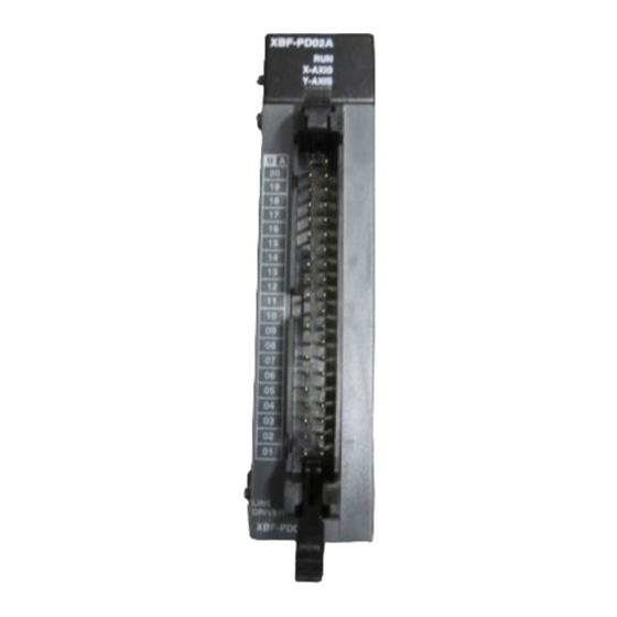
Chapter 2 Specifications 2.4 The Name of Each Part 2.4.1 The name of each part ① ② ③ Name Description 1. RUN : indicates whether power is supplied or not 2. X-AXIS, Y-AXIS Operating indication ▶ On : during corresponding axis operation ①... -
Page 34: Connection To Xgt Servo System
Chapter 2 Specifications 2.5 Connection to XGT Servo System The following shows the basic wiring diagram of XGB positioning module and XGT Servo System XDA-S Series. This wiring diagram is written based on axis X. Note *Note 1 The external input signal of XGT Servo Drive can be changed by setting the parameter of servo drive. The number allocated in the wiring diagram shows the case when setting the parameter of servo drive to “Position control setting mode (Ph07-01=27).”... -
Page 35: Chapter 3 Operation Order And Installation
Chapter 3 Operation Order and Installation Chapter 3 Operation Order and Installation 3.1 Installation 3.1.1 Installation Environment This machine has a good reliability regardless of installation environment but cares should be taken in the following items to guarantee the reliability and safety of the system. (1) Environment Condition (a) Install the control panel available for water-proof, anti-vibration. -
Page 36: Notices In Wiring
Chapter 3 Operation Order and Installation 3.2 Notices in Wiring 3.2.1 Notices in Wiring (1) The length of connecting cable between positioning module and drive machine shall be as short as possible. (Max. length : 10m). (2) For cross current and external I/O signal of positioning module, it is required to use the separate cables to avoid the surge or induction noise generated from the cross current. -
Page 37: Connection Example Of Servo And Stepping Motor Drive Machine
Chapter 3 Operation Order and Installation 3.2.2 Connection Example of Servo and Stepping Motor Drive Machine Notes ▶ Connection example shows the case that the input signal parameter of positioning module is set as follows. • High limit signal/Low limit signal: B contact point •... - Page 38 Chapter 3 Operation Order and Installation (b) MR-J2/J2S-□A Connection HC-MF HA-FF Series motor MR-J2S- A TE11 power 3 phase 200VAC CTE2 24VDC Electonic breaker Servo ON signal OFF CN1A Within 10m Cutoff by alarm signal Detector XBF-PD02A HOME +5V HOME COM Personal Upper limit computer...
- Page 39 Chapter 3 Operation Order and Installation (c) MR-J□A Connection Regenerative option Servo mortor N C P MR-J A power 3-phase AC200V Detector Within 10m XBF-PD02A Upper limit Lower limit servo ON Reset Torque limit Forward limit Within 30m DC24V Backward limit P15R HOME +5V HOME COM...
- Page 40 Chapter 3 Operation Order and Installation (d) MR-C□A Connection Regenerative resistance (Option) HC-PQ Series motor power single phase 200VAC(A type) or single phase 100VAC(A1 type) MR-C A or MR-C A1 24VDC electronic brake servo ON OFF Detector Cutoff by alarm signal Within 10m XBF-PD02A ㏀,...
- Page 41 Chapter 3 Operation Order and Installation (2) PANASONIC (a) A Series Connection (Line Driver) Max. 10m XBF-PD02A MINAS A PULSE2 PULSE1 SIGN2 SIGN1 HOME +5V HOME COM S-RDY+ S-RDY- SRV-QN MPG A+ CCWL MPG A- MPG B+ COM+ MPG B- Upper limit Lower limit P24V...
- Page 42 Chapter 3 Operation Order and Installation (3) VEXTA (a) UDX2107 Connection Max. 10m VEXTA UDX2107 XBF-PD02A CCW+ CCW- ㏀, HOME +5V H OFF+ 1/4W H OFF- HOME COM TIMING Upper limit Connect when required Lower limit P24V MPG A+ MPG A- MPG B+ MPG B- (b) UPD Connection...
- Page 43 Chapter 3 Operation Order and Installation (c) FX Connection Max. 10m XBF-PD02A VEXTA-FX CCW+ CCW- HOME +5V H.OFF+ HOME COM H.OFF- ENC A ENC B Upper limit ENC Z Lower limit P.END ALARM P24V ENC A ENC B ENC Z P.END ALARM MPG A+...
- Page 44 Chapter 3 Operation Order and Installation (4) Hagen Motor (a) FDA-5000/6000/7000 AC Servo Drive Connection Max. 10m XBF-PD02A FDA-5000/6000 PPFIN PFIN PPRIN PRIN HOME +5V PZO+ PZO- HOME COM INPOS 0 SPEED Upper limit BRAKE Lower limit ALARM A_CODE0 P24V A_CODE1 A_CODE2 GND24...
- Page 45 Chapter 3 Operation Order and Installation (5) YASKAWA (a) CACR(R Series) Connection Max. 10m CACR (R Series) XBF-PD02A Servopack PULS *PULS SIGN *SIGN HOME +5V PCOT HOME COM S-ON ALM RST N-OT P-OT Upper limit +24VIN Lower limit P24V MPG A+ MPG A- MPG B+ MPG B-...
- Page 46 Chapter 3 Operation Order and Installation (c) ∑-Ⅱ Series SGDH AC Servo Drive Connection max 10m SGDH XBF-PD02A PULS BAT(+) /PULS BAT(-) SIGN /SIGN /CLR P24V ALO1 HOME +5V ALO2 HOME COM ALO3 V-CMP+(/COIN+) Upper limit V-CMP-(/COIN-) Lower limit /TGON+ /PAO /TGON- P24V...
-
Page 47: Encoder Input (Dc 5V Voltage Output) Wiring Example
Chapter 3 Operation Order and Installation 3.2.3 Encoder Input (DC 5V Voltage Output) Wiring Example When Pulse Generator is a Voltage Output type, wiring example of positioning module and Encoder entry are as follows. In case of pulse generator uses by voltage output style by totem-pole output, wiring is equal. Pulse generating point XBF-PD02A XGF-P□□H... -
Page 48: Encoder Input (5V Line Driver Output) Wiring Example
Chapter 3 Operation Order and Installation 3.2.4 Encoder Input (5V Line Driver Output) Wiring Example XBF-PD02A Notes Before Wiring, please consider maximum output distance of pulse generator. 3-14... -
Page 49: Chapter 4 Positioning Parameter & Operation Data
Chapter 4 Positioning Parameter & Operation Data Chapter 4 Positioning Parameter & Operation Data This chapter describes parameter and operation data Item of Parameter and operation data should be set at each axis. (But common parameter shall be applied to all axes equally) Parameter &... -
Page 50: Basic Parameter
Chapter 4 Positioning Parameter & Operation Data 4.2 Basic Parameter ▶ Here describes about basic parameter of positioning module. 4.2.1 Basic parameter Basic parameter item Setting range Pulse output level 0: Low Active, 1: High Active Pulse output mode 0: CW/CCW, 1: PLS/DIR M code output mode 0: None, 1: With, 2: After Bias speed... -
Page 51: Basic Parameter Setting
Chapter 4 Positioning Parameter & Operation Data 4.2.2 Basic parameter setting (1) Pulse output level You can select one between Low Active and High Active as pulse output level. For Low Active output, select 0. For High Active output, select 1. (2) Pulse Output Mode As input method to be used for SERVO Driver or Stepping Driver is different, it is required to select pulse output mode of positioning module according to the input method. - Page 52 Chapter 4 Positioning Parameter & Operation Data Notes If M code signal is “ON” even if the positioning is completed, the next operation step no. does not work and the error (E233) will occur. Therefore, in order to act the positioning of the next operation step number, M code signal should be “OFF”...
- Page 53 Chapter 4 Positioning Parameter & Operation Data 2) After mode This is the mode that outputs M code number to be set by position data after completing the positioning by start command (indirect start, direct start, circular interpolation, simultaneous start, linear interpolation) and at the same time outputs M code ON signal (4) Bias Speed As the stepping motor has unstable torque near speed=0, the start speed shall be set in the beginning of operation in command...
- Page 54 Chapter 4 Positioning Parameter & Operation Data Note 1. If Bias speed is set as high, total operation time shall be reduced but if the setting value is too high, it may cause the occurrence of impact sound in the start/end time and forces the excessive effect to the machine.
- Page 55 Chapter 4 Positioning Parameter & Operation Data (6) Software Upper/Lower Limit (a) The function is designed so that the machine does not execute the positioning operation out of the range by setting the range of machine available to move as software upper limit and software lower limit. That is, this function is used to prevent any derailment of incorrect operation position setting and incorrect operation by user program fault.
- Page 56 Chapter 4 Positioning Parameter & Operation Data (7) Backlash Compensation Amount (a) The tolerance that the machine does not work by the wear when the rotation direction changes in case that a gear, screw etc is combined to run at the motor axle, is called as ‘Backlash”. Therefore, when you change the rotation direction, it is required to add the backlash compensation amount to the positioning amount for output.
- Page 57 Chapter 4 Positioning Parameter & Operation Data 1) Method by dwell time In case that in-position signal is ON when positioning is completed after dwell time. 2) Method by in-position signal a) In case that in-position signal is ON before positioning is completed...
- Page 58 Chapter 4 Positioning Parameter & Operation Data b) In case of In-positioning signal to be On after positioning is ended. 3) Method by using both dwell time and in-position signal a) In case that in-position signal occurs before dwell time is ended 4-10...
- Page 59 Chapter 4 Positioning Parameter & Operation Data b) In case that in-position signal occurs after dwell time is ended. c) In case that in-position signal occurs during pulse output 4-11...
- Page 60 Chapter 4 Positioning Parameter & Operation Data 4) Method by using either dwell time or in-position signal a) In case that in-position signal occurs before dwell time is ended b) In case that in-position signal occurs after dwell time is ended. (10) Use of upper/lower limit When you use upper/lower limit, set this tiem as “Use”.
-
Page 61: Home/Manual Parameter
Chapter 4 Positioning Parameter & Operation Data 4.3 Home/Manual parameter Describes Home/Manual parameter of XGB positioning module 4.3.1 Contents of Home/Manual parameter Home parameter items Setting range 0:DOG/HOME(Off), 1:DOG/HOME(On), 2: DOG, Home method 3: U.L Limit/Home, 4: U.L Limit Home direction 0:CW, 1: CCW -2,147,483,648 ∼... - Page 62 Chapter 4 Positioning Parameter & Operation Data (3) Origin Address (a) When homing is completed by homing command, the value set by homing address shall be used to change the present address value. (b) Setting range of homing address: -2,147,483,648 ∼ 2,147,483,647(pulse) (4) Homing-High speed (a) The speed when returning to the origin by homing command : high speed and low speed.
- Page 63 Chapter 4 Positioning Parameter & Operation Data (7) Homing accelerating speed/ deceleration speed (a) When it returns by homing command, it will be accelerated or decelerated by set acceleration time and deceleration time. (b) Setting range is 0 ~ 65,535 [ms]. (c) It will be accelerated or decelerated according to speed limit set at basic parameter (8) Homing dwell time (a) This is the time needed to maintain the precise stop accuracy of SERVO motor when using the SERVO motor for positioning.
-
Page 64: Common Parameter
Chapter 4 Positioning Parameter & Operation Data (10) JOG Low Speed (a) JOG low speed operation has operation pattern as acceleration, constant speed, deceleration section. (b) JOG low speed setting range : Bias speed Jog high speed ∼ (11) JOG Acceleration/Deceleration Time (a) This means JOG acceleration/deceleration time when Jog high speed and low speed operation. - Page 65 Chapter 4 Positioning Parameter & Operation Data 2) In case of decreasing encoder value (2) Speed override (a) When operate changing speed command (Speed override, Positioning speed override, etc), select speed(will be changed) or percentage of goal speed. (b) in case of setting percentage(%) can set each per 0.01% from 0.01% to 655.35%. (3) Encoder pulse input mode (a) If you want to use by signal of a hand pulse generator or Servo drive encoder, can select suitable signal of a hand pulse generator or Survo drive encoder for using.
- Page 66 Chapter 4 Positioning Parameter & Operation Data 2) PULSE/DIR 1 multiplier In case of increasing Phase A input pulse, act to count. Addition/cutback was decided by Phase B. Increasing Phase A input Decreasing Phase A input pulse pulse Phase B input pulse Off Increase count Phase B input pulse On Decrease count...
-
Page 67: I/O Signal Parameter
Chapter 4 Positioning Parameter & Operation Data 4.5 I/O Signal Parameter ▶ Here describes using input/output signal parameter in positioning module. Input/output signal parameter use to decide act level of input signal. ▶ 4.5.1 I/O Signal Parameter Input/output signal parameter Setting range configuration Upper limit signal... -
Page 68: Operation Data
Chapter 4 Positioning Parameter & Operation Data 4.6 Operation Data Here describes Operation Data of positioning module. ▶ ▶ Can set 150 operation data per each axis, operation of circular interpolation and Linear interpolation act in accordance with information of operation data. 4.6.1 Operation Data Operation data item Setting range... - Page 69 Chapter 4 Positioning Parameter & Operation Data (2) Coordinate (a) Coordinate of position data includes absolute coordinate and incremental coordinate. 1) Absolute Coordinate (Control by Absolute method) a) This carries out the positioning control from the current position to the goal position (the goal position assigned by positioning data).
- Page 70 Chapter 4 Positioning Parameter & Operation Data (3) Control Method (End/KEEP/CONT) (a) Decides how to connect the current and next step (b) Select one among END, KEEP, CONT as you desire (c) For further information, please refer to 9.2.2 operation mode of positioning control of Chapter 9 “Function”. (4) Method (a) There are SPD, POS in method.
- Page 71 Chapter 4 Positioning Parameter & Operation Data (10) M Code (a) M code is applied to the whole axis in a bundle by M code mode set by positioning parameter and is given to each operation step no. as a Number within the setting range to use at Program. (b) The setting range is 1 ∼...
- Page 72 Chapter 4 Positioning Parameter & Operation Data (16) Circular arc size (a) When circular interpolating method is set by radius method, User can select one of 2 circular arcs. (b) Select one of over the 180-degree circular interpolation or under the 180-degree circular interpolation. (c) This option is ignored in the circular interpolation of midpoint method and central point method.
-
Page 73: Internal Memory
Chapter 5 Internal Memory and I/O Signal Chapter 5 Internal Memory and I/O Signal 5.1 Internal Memory ▶Here describes the internal memory used for XGB positioning module ▶ Internal memory is used when executing direct Data read/write between positioning module and PLC main unit by using PUP(PUTP), GET(GETP) command instead of using the dedicated command. - Page 74 Chapter 5 Internal Memory and I/O Signal (2) Setting (a) The command of Teaching data setting is TWR. (b) References for TEAA and TWR are on ‘Chapter 6.3.24. (c) In PLC program, in order to carry out the normal action of Teaching command, the Teaching data setting should be done in the step before Teaching command is executed.
-
Page 75: State Information
Chapter 5 Internal Memory and I/O Signal 5.1.2 State Information (1) Memory Address of State Information Memory address (HEX) Information Axis X Axis Y Operation state bit information (Lower) Operation state bit information (Upper) Axis information External I/O signal state Current Position ( Lower) Current Position ( Upper) Current Speed (Lower) - Page 76 Chapter 5 Internal Memory and I/O Signal (e) Use of State Information 1) Operation State Bit Information (Lower) Memory Address Information Axis X Axis Y Operation State bit Information (Lower)
- Page 77 Chapter 5 Internal Memory and I/O Signal 2) Operation State Bit Information (Upper) Memory address Information Axis X Axis Y Operation State Bit Information (UPPER)
- Page 78 Chapter 5 Internal Memory and I/O Signal 3) Axis Information Memory address Information Axis X Axis Y Axis information...
- Page 79 Chapter 5 Internal Memory and I/O Signal 4) External I/O Signal State Memory address Information Axis X Axis Y Axis information...
-
Page 80: I/O Signal
Chapter 5 Internal Memory and I/O Signal 5.2 I/O Signal Here describes the contents and functions of I/O signal for the exchange of data between Positioning module and main unit. 5.2.1 Contents of I/O Signal (1) I/O signal of positioning module uses input: 16 bits and output: 16 bits. (2) Positioning Module operation ready signal (Uxx.00.F) becomes “ON”... -
Page 81: Use Of I/O Signal
Chapter 5 Internal Memory and I/O Signal 5.2.2 Use of I/O Signal (1) JOG Operation (a) Forward/Reverse Jog Signals show the direction of Jog Operation. The Jog operation shall be divided into Forward/Reverse direction according to the On/Off signals. When Forward Jog Signal is on, it starts Forward Operation and When Jog Signal is Off, it starts Reverse Operation. - Page 82 Chapter 5 Internal Memory and I/O Signal (2) Positioning complete signal clear (a) It is used to turn off positioning complete signal after complete of single operation, repeated operation, continuous operation, liner interpolation operation, circular interpolation operation, speed/position conversion control operation and inching operation. (b) In the following two cases, positioning complete signal is off - If positioning complete signal clear bits (Axis X: Uxx.01.3.
-
Page 83: Chapter 6 Command
Chapter 6 Command Chapter 6 Command Here describes the positioning command. 6.1 Contents of General Command Command Command description Command condition Internal memory write Base, memory address, save device leading address, data number to write at (Level) one time Internal memory write Base, memory address, save device leading address, data number to write at... -
Page 84: Internal Memory Write
Chapter 6 Command 6.1.2 Internal Memory Write (PUT, PUTP Command) Form Description Available area Base and slot No. installed with special module Constant Leading address of special module internal memory to write a data Constant Leading address of device that the data to Write is saved M, P, K, L, U, N, D, R Word number of data to write M, P, K, L, Constant... -
Page 85: Dedicated Commands
Chapter 6 Command 6.2 Dedicated Commands Command Description Condition Homing start Slot, command axis Floating origin setting Slot, command axis Direct start Slot, command axis, position, speed, dwell time, M code, control word Indirect start Slot, command axis, step number Linear interpolation Slot, command axis, step number, axis setting Circular interpolation... -
Page 86: Use Of Dedicated Command
Chapter 6 Command 6.3 Use of Dedicated Command 6.3.1 Homing start (Command : ORG) (1) Program (2) Description Device Description M00000 Axis X homing start input D00000.0 Axis X in operation D00000.1 Axis X error Command Homing start Slot Constant WORD Slot No. -
Page 87: Floating Origin Setting (Command : Flt)
Chapter 6 Command 6.3.2 Floating origin setting (Command : FLT) (1) Program (2) Description Device Description M00001 Axis X floating origin setting D00000.0 Axis X in operation D00000.1 Axis X error Command Floating origin setting Slot Constant WORD Slot No. installed with positioning module Operand Axis PMLK,constant,D,Z,R,ZR... -
Page 88: Direct Start (Command : Dst)
Chapter 6 Command 6.3.3 Direct start (Command : DST) (1) Program (2) Description Device Description M00002 Axis X direct start input D00000.0 Axis X in operation D00000.1 Axis X error state Command Direct start Slot Constant WORD Slot No. installed with positioning module Axis PMLK,constant,D,Z,R,ZR WORD... -
Page 89: Indirect Start (Command : Ist)
Chapter 6 Command 6.3.4 Indirect start (Command : IST) (1) Program (2) Description Device Description M00003 Axis X indirect start input D00000.0 Axis X in operation D00000.1 Axis X error state D01300 Axis X step no. Command Indirect start Slot Constant WORD Slot No. -
Page 90: Linear Interpolation (Command: Lin)
Chapter 6 Command 6.3.5 Linear Interpolation (Command: LIN) (1) Program (2) Description Device Description M00006 Linear interpolation D00000.0 Axis X in operation D00000.1 Axis X error status D00100.0 Axis Y in operation D00100.1 Axis Y error status D01500 Operation step Command Direct start Slot... -
Page 91: Circular Interpolation (Command: Cin)
Chapter 6 Command 6.3.6 Circular Interpolation (Command: CIN) (1) Program (2) Description Device Description M00007 Circular interpolation D00000.0 Axis X in operation D00000.1 Axis X error status D00100.0 Axis Y in operation D00100.1 Axis Y error status D01500 Operation step Command Direct start Slot... -
Page 92: Simultaneous Start (Command : Sst)
Chapter 6 Command 6.3.7 Simultaneous Start (Command : SST) (1) Program (2) Description Device Description M00004 Simultaneous start D00000.0 Axis X in operation D00000.1 Axis X error status D00100.0 Axis Y in operation D00100.1 Axis Y error status D01300 Axis X simultaneous start step D01400 Axis Y simultaneous start step Command... -
Page 93: Speed/Position Switching Control (Command : Vtp)
Chapter 6 Command 6.3.8 Speed/Position Switching Control (Command : VTP) (1) Program (2) Description Device Description M00008 Axis X speed/position switching control input D00000.0 Axis X in operation D00000.1 Axis X error state D00001.1 Axis X in speed control Command Speed/position switching control Slot Constant... -
Page 94: Position/Speed Switching Control (Command : Ptv)
Chapter 6 Command 6.3.9 Position/Speed Switching Control (Command : PTV) (1) Program (2) Description Device Description M00009 Axis X position/speed switching control input D00000.0 Axis X in operation D00000.1 Axis X error state D00001.0 Axis X in position control Command Position/speed switching control Slot Constant... -
Page 95: Deceleration Stop (Command : Stp)
Chapter 6 Command 6.3.10 Deceleration Stop (Command : STP) (1) Program (2) Description Device Description M0000A Axis X deceleration stop input D00000.0 Axis X in operation D00000.1 Axis X error state D01500 Axis X deceleration stop time set Command Deceleration stop Slot Constant WORD... -
Page 96: Synchronous Start By Position (Command : Ssp)
Chapter 6 Command 6.3.11 Synchronous Start by Position (Command : SSP) (1) Program (2) Description Device Description M0000C Axis X synchronous start by position input M00002 Axis X direct start input D00000.0 Axis X in operation D00000.1 Axis X error signal D00100.0 Axis Y in operation D00100.1... -
Page 97: Synchronous Start By Speed (Command : Sss)
Chapter 6 Command 6.3.12 Synchronous Start by Speed (Command : SSS) (1) Program (2) Description Device Description M0000E Axis Y speed synchronous start input M00002 Axis X direct start input D00000.0 Axis X in operation D00000.1 Axis X error state D00100.0 Axis Y in operation D00100.1... -
Page 98: Position Override (Command : Por)
Chapter 6 Command 6.3.13 Position Override (Command : POR) (1) Program (2) Description Device Description M0000F Axis X position override input M00002 Axis X direct start input D00000.0 Axis Xl in operation D00000.1 Axis X error state D01100 Goal position value D02800 Position override value Command... -
Page 99: Speed Override (Command : Sor)
Chapter 6 Command 6.3.14 Speed Override (Command : SOR) (1) Program (2) Description Device Description M00012 Axis X speed override input M00002 Axis X direct start input D00000.0 Axis X in operation D00000.1 Axis X error state D01200 Goal speed value D01600 Speed override value Command... -
Page 100: Position Assigned Speed Override (Command : Pso)
Chapter 6 Command 6.3.15 Position Assigned Speed Override (Command : PSO) (1) Program (2) Description Device Description M00013 Axis X position assigned speed override input M00002 Axis X direct start input D00000.0 Axis X in operation D00000.1 Axis X error state D01200 Goal speed value D01600... -
Page 101: Inching Operation (Command : Inch)
Chapter 6 Command 6.3.16 Inching Operation (Command : INCH) (1) Program (2) Description Device Description M00014 Axis X inching operation input D00000.0 Axis X in operation D00000.1 Axis X error state D01000 Axis X inching value Command XINCH Inching operation Slot Constant WORD... -
Page 102: Start Step No. Change (Command : Sns)
Chapter 6 Command 6.3.17 Start Step No. Change (Command : SNS) (1) Program (2) Description Device Description M00018 Axis X start step No. change input D00000.0 Axis X in operation D00000.1 Axis X error state D01300 Axis X start step no. to change Command Start step No. -
Page 103: Repeat Step No. Change (Command : Srs)
Chapter 6 Command 6.3.18 Repeat Step No. Change (Command : SRS) (1) Program (2) Description Device Description M00019 Axis X start step No. change input D00000.1 Axis X error state D01300 Axis X repeat step no. to change Command XSRS Repeat step No. -
Page 104: M Code Release (Command : Mof)
Chapter 6 Command 6.3.19 M code Release (Command : MOF) (1) Program (2) Description Device Description M0001A Axis X M code release input D00000.1 Axis X error state D00000.3 Axis X M code signal Command M code release Slot Constant WORD Slot No. -
Page 105: Current Position Preset (Command : Prs)
Chapter 6 Command 6.3.20 Current Position Preset (Command : PRS) (1) Program (2) Description Device Description M0001B Axis X current position preset input D00000.0 Axis X in operation D00000.1 Axis X error state D02900 axis1 preset position value Command Current position preset Slot Constant WORD... -
Page 106: Encoder Preset (Command : Eprs)
Chapter 6 Command 6.3.21 Encoder Preset (Command : EPRS) (1) Program (2) Description Device Description M0001C Encoder preset input D02910 Encoder preset position value Command EPRS Encoder preset Slot Constant WORD Slot No. installed with positioning module Operand Axis PMLK,constant,D,Z,R,ZR WORD Command axis (0: axis X, 1: axis Y) Setting value... -
Page 107: Single Teaching (Command: Tea)
Chapter 6 Command 6.3.22 Single Teaching (Command: TEA) (1) Program (2) Description Device Description M0001D Axis X single teaching input D00000.0 Axis X in operation D00000.1 Axis X error status D03000 Teaching D01300 Teaching step D03010 Select RAM/ROM teaching D02000 Select position/speed Command Single teaching... -
Page 108: Teaching Array(Command : Teaa)
Chapter 6 Command 6.3.23 Teaching Array (Command : TEAA) (1) Program (2) Description Device Description M0001F Axis X teaching data setting input M00020 Axis X teaching array input D00000.0 Axis X in operation D00000.1 Axis X error state D02000 Axis X teaching array data leading address Command TEAA Teaching Array... -
Page 109: Teaching Array Data Setting (Command: Twr)
Chapter 6 Command 6.3.24 Teaching Array Data Setting (Command: TWR) (1) Program (2) Description Device Description M0001F Axis X Teaching array data setting input M00020 Axis X Teaching array input D00000.0 Axis X in operation D00000.1 Axis X error state D02000 Axis X Teaching array data leading address Command... - Page 110 Chapter 6 Command (e) Teaching array data can be set by using PUT command. For this, refer to memory address of “5.1.1 Teaching data” and “6.1.2 Internal Memory Writing”. If use PUT command in the example program above, it displayed like the picture below. (f) D device signal (axis X in Operation, etc) which used in the example above is an assumption that saving the axis state value in D device area with SRD command.
-
Page 111: Basic Parameter Teaching (Command : Tbp)
Chapter 6 Command 6.3.25 Basic Parameter Teaching (Command : TBP) (1) Program (2) Description Device Description M00021 Axis X basic parameter setting input D00000.0 Axis X in operation D00000.1 Axis X error state D03000 Parameter value D03012 Parameter items Command Basic parameter Teaching Slot No. - Page 112 Chapter 6 Command Setting Items Setting Range Value Use of upper/lower limit 0: Not use, 1: Use Pulse output level 0: Low Active, 1: High Active Pulse output mode 0: CW/CCW, 1: PLS/DIR M code output mode 0: None, 1: With, 2: After (e) For the change value (OP3) setting range of each basic parameter item (OP4) which already set, refer to “4.2 Basic Parameter Content”...
-
Page 113: Homing/Manual Parameter Teaching (Command : Thp)
Chapter 6 Command 6.3.26 Homing/Manual Parameter Teaching (Command : THP) (1) Program (2) Description Device Description M00022 Axis X homing parameter teaching input D00000.0 Axis X in operation D00000.1 Axis X error state D03000 Parameter value D03012 Parameter Items Command Homing parameter Teaching Slot Constant... - Page 114 Chapter 6 Command (g) If you want to set entire item of basic parameter with one execution of THP command, set hFF(255) at OP4. At this time, basic parameter should be saved in the following address. Memory address (HEX) Contents Setting range Axis X Axis Y...
-
Page 115: I/O Signal Parameter Teaching (Command : Tsp)
Chapter 6 Command 6.3.27 I/O Signal Parameter Teaching (Command : TSP) (1) Program (2) Description Device Description M00023 Axis X input signal parameter teaching input D00000.0 Axis X in operation D00000.1 Axis X error state D03000 Parameter value Command Input signal parameter Teaching Slot Constant WORD... -
Page 116: Common Parameter Teaching (Command : Tcp)
Chapter 6 Command 6.3.28 Common Parameter Teaching (Command : TCP) (1) Program (2) Description Device Description M00024 Common parameter setting input D02100 Parameter value D02102 Parameter items Command XSCP Common parameter Setting Slot No. installed with positioning Slot Constant WORD module Operand Axis... -
Page 117: Operation Data Teaching (Command: Tmd)
Chapter 6 Command 6.3.29 Operation Data Teaching (Command: TMD) (1) Program (2) Description Device Description M00025 Axis X Operation data setting input D00000.0 Axis X in operation D00000.1 Axis X error state D03000 Operation data value D03012 Operation data items D01300 Teaching step Command... - Page 118 Chapter 6 Command Setting value Item Setting range Acc. no. 0 ~ 3 Dec. no. 0 ~ 3 Cir. Int. mode 0:MID, 1:CENTER, 2:RADIUS Cir. Int. direction 0:CW, 1:CCW Repeat step number 1~150 (d) For the change value (OP3) setting range of each position data item (OP4) which already set, refer to “4.6.1 Operation Data Content”...
-
Page 119: Parameter/Operation Data Save (Command : Wrt)
Chapter 6 Command 6.3.30 Parameter/Operation Data Save (Command : WRT) (1) Program (2) Description Device Description M00026 Axis X parameter/operation data save input D00000.1 Axis X error state Command Parameter/operation Data save Slot Constant WORD Slot No. installed with positioning module Operand Axis PMLK,constant,D,Z,R,ZR... -
Page 120: Emergency Stop (Command : Emg)
Chapter 6 Command 6.3.31 Emergency Stop (Command : EMG) (1) Program (2) Description Device Description M00027 Axis X internal emergency stop input Command Emergency stop Slot Constant WORD Slot No. installed with positioning module Operand Axis PMLK,constant,D,Z,R,ZR WORD Command axis (0: axis X, 1: axis Y) ※... -
Page 121: Operation State Reading (Command: Srd)
Chapter 6 Command 6.3.33 Operation State Reading (Command: SRD) (1) Program (2) Description Device Description F00029 Axis operation status reading input D04000 Leading address to save operation status of axis X Command Operation state reading Slot Constant WORD Slot No. installed with positioning module Axis PMLK,constant,D,Z,R,ZR WORD... -
Page 122: Chapter 7 Function Block
Chapter 7 Function Block Chapter 7 Function Block 7.1 Common Issues of Function Block (1) The functions and directions of the following I/O parameter are common for positioning function block. Data Description Category Parameter Type Execution request of function block BOOL - Function block is executed if “0 1”... -
Page 123: Function Block Of Positioning Module
Chapter 7 Function Block 7.2 Function Block of Positioning Module Here describes the positioning function blocks. Operation Name Description condition Homing start APM_ORG Edge Floating origin setting APM_FLT Edge Direct start APM_DST Edge APM_IST Indirect start Edge Linear interpolation APM_LIN Edge APM_CIN Circular interpolation... -
Page 124: Function Block Related To Module Information Read
Chapter 7 Function Block 7.3 Function Block related to Module Information Read 7.3.1 Operation Information Read (APM_CRD) Form of Function Block Description Input REQ : Request for execution of function block BASE : Set the base no. with module BOOL DONE BOOL SLOT : Set the slot no. -
Page 125: Operation State Bit Information Read (Apm_Srd)
Chapter 7 Function Block 7.3.2 Operation State Bit Information Read (APM_SRD) Form of Function Block Description Input REQ : Request for execution of function block BASE : Set the base no. with module SLOT : Set the slot no. with module AXIS : Axis to command (0: axis X. - Page 126 Chapter 7 Function Block Description Description Main axis information 1: axis X, 2: axis Y, 4: Encoder Axis state (0: main axis, 1: sub axis) High limit signal Low limit signal Origin signal DOG signal In-position signal Declination counter clear output signal...
-
Page 127: Encoder Value Read (Apm_Encrd)
Chapter 7 Function Block 7.3.3 Encoder Value Read (APM_ENCRD) Form of Function Block Description Input REQ : Request for execution of function block BASE : Set the base no. with module SLOT : Set the slot no. with module Output DONE : Maintain 1 after first operating STAT : Output the error no. -
Page 128: Parameter/Operation Data Teaching Function Block
Chapter 7 Function Block 7.4 Parameter/Operation Data Teaching Function Block 7.4.1 Basic Parameter Teaching (APM_SBP) Form of Function Block Description Input REQ : Request for execution of function block BASE : Set the base no. with module SLOT : Set the slot no. with module AXIS : Axis to command BP_VAL : Basic parameter to change BP_NO : Item no. -
Page 129: Homing/Manual Parameter Teaching (Apm_Shp)
Chapter 7 Function Block 7.4.2 Homing/Manual Parameter Teaching (APM_SHP) Form of Function Block Description Input REQ : Request for execution of function block BASE : Set the base no. with module SLOT : Set the slot no. with module AXIS : Axis to command HP_NO : Item no. -
Page 130: I/O Signal Parameter Teaching (Apm_Sip)
Chapter 7 Function Block 7.4.3 I/O Signal Parameter Teaching (APM_SIP) Form of Function Block Description Input REQ : Request for execution of function block BASE : Set the base no. with module SLOT : Set the slot no. with module AXIS : Axis to command IP_VAL : External signal parameter value to modify Set the corresponding signal for each Bit... -
Page 131: Common Parameter Teaching (Apm_Scp)
Chapter 7 Function Block 7.4.4 Common Parameter Teaching (APM_SCP) Form of Function Block Description Input REQ : Request for execution of function block BASE : Set the base no. with module SLOT : Set the slot no. with module AXIS : Axis to command CP_NO : Item no. -
Page 132: Operation Data Teaching (Apm_Smd)
Chapter 7 Function Block 7.4.5 Operation Data Teaching (APM_SMD) Form of Function Block Description Input REQ : Request for execution of function block BOOL DONE BOOL BASE : Set the base no. with module BASE USINT STAT UINT SLOT : Set the slot no. with module USINT SLOT AXIS : Axis to command... -
Page 133: Single Teaching (Apm_Tea)
Chapter 7 Function Block 7.4.6 Single Teaching (APM_TEA) Form of Function Block Description Input REQ : Request for execution of function block BOOL DONE BOOL BASE : Set the base no. with module SLOT : Set the slot no. with module BASE USINT STAT... -
Page 134: Teaching Array (Apm_Atea)
Chapter 7 Function Block 7.4.7 Teaching Array (APM_ATEA) Form of Function Block Description Input REQ : Request for execution of function block BASE : Set the base no. with module SLOT : Set the slot no. with module AXIS : Axis to command STEP : Set the step no. -
Page 135: Saving Parameter/Operation Data (Apm_Wrt)
Chapter 7 Function Block 7.4.8 Saving Parameter/Operation Data (APM_WRT) Form of Function Block Description Input REQ : Request for execution of function block BASE : Set the base no. with module SLOT : Set the slot no. with module AXIS : Axis to command WRT_AXIS : Saving axis setting (by setting bit) Bit0: axis X, Bit1: axis Y Output... -
Page 136: Start/Stop Function Block
Chapter 7 Function Block 7.5 Start/Stop Function Block 7.5.1 Homing Start (APM_ORG) Form of Function Block Description Input REQ : Request for execution of function block BASE : Set the base no. with module SLOT : Set the slot no. with module AXIS : Axis to command Output DONE : Maintain 1 after first operation... - Page 137 Chapter 7 Function Block 7.5.2 Direct Start (APM_DST) Form of Function Block Description Input REQ : Request for execution of function block BASE : Set the base no. with module SLOT : Set the slot no. with module BOOL DONE BOOL AXIS : Axis to command BASE...
-
Page 138: Indirect Start (Apm_Ist)
Chapter 7 Function Block 7.5.3 Indirect Start (APM_IST) Form of Function Block Description Input REQ : Request for execution of function block BASE : Set the base no. with module SLOT : Set the slot no. with module AXIS : Axis to command STEP : Set the step no. -
Page 139: Linear Interpolation (Apm_Lin)
Chapter 7 Function Block 7.5.4 Linear Interpolation (APM_LIN) Form of Function Block Description Input REQ : Request for execution of function block BASE : Set the base no. with module SLOT : Set the slot no. with module LIN_AXIS: linear interpolation axis (fixed as 3 in XGB positioning module) STEP : Step no. -
Page 140: Circular Interpolation (Apm_Cin)
Chapter 7 Function Block 7.5.5 Circular interpolation (APM_CIN) Form of Function Block Description Input REQ : Request for execution of function block BOOL DONE BOOL BASE : Set the base no. with module BASE STAT UINT SLOT : Set the slot no. with module USINT AXIS : Axis to command USINT... - Page 141 Chapter 7 Function Block 7.5.6 Simultaneous Start (APM_SST) Form of Function Block Description Input REQ : Request for execution of function block BOOL DONE BOOL BASE : Set the base no. with module BASE STAT UINT USINT SLOT : Set the slot no. with module USINT SLOT SST_AXIS : Simultaneous axis setting...
-
Page 142: Deceleration Stop (Apm_Stp)
Chapter 7 Function Block 7.5.7 Deceleration Stop (APM_STP) Form of Function Block Description Input REQ : Request for execution of function block BASE : Set the base no. with module SLOT : Set the slot no. with module AXIS : Axis to command DEC_TIME : Decelerating stop time 0: Acc./Dec. -
Page 143: Emergency Stop (Apm_Emg)
Chapter 7 Function Block 7.5.8. Emergency Stop (APM_EMG) Form of Function Block Description Input REQ : Request for execution of function block BOOL DONE BOOL BASE : Set the base no. with module BASE USINT STAT UINT SLOT : Set the slot no. with module Output USINT SLOT... -
Page 144: Manual Operation Function Block
Chapter 7 Function Block 7.6 Manual Operation Function Block 7.6.1 Inching Operation (APM_INC) Form of Function Block Description Input REQ : Request for execution of function block BASE : Set the base no. with module SLOT : Set the slot no. with module AXIS : Axis to command INCH_VAL: Amount of movement by Inching Operation... -
Page 145: Synchronization Start Function Blocks
Chapter 7 Function Block 7.7 Synchronization Start Function Blocks 7.7.1 Position Synchronization (APM_SSP) Form of Function Block Description Input REQ : Request for execution of function block BASE : Set the base no. with module SLOT : Set the slot no. with module AXIS : Axis to command STEP : Step no. -
Page 146: Speed Synchronization (Apm_Sss)
Chapter 7 Function Block 7.7.2 Speed Synchronization (APM_SSS) Form of Function Block Description Input REQ : Request for execution of function block BASE : Set the base no. with module SLOT : Set the slot no. with module AXIS : Axis to command MST_AXIS : Set main axis 0~2: axis X, axis Y, encoder MST_RAT : Set speed rate of main axis... -
Page 147: Modification Function Block
Chapter 7 Function Block 7.8 Modification Function Block 7.8.1 Position Override (APM_POR) Form of Function Block Description Input REQ : Request for execution of function block BASE : Set the base no. with module SLOT : Set the slot no. with module AXIS : Axis to command POR_ADDR : Set a new goal position ∼... -
Page 148: Speed Override (Apm_Sor)
Chapter 7 Function Block 7.8.2 Speed Override (APM_SOR) Form of Function Block Description Input REQ : Request for execution of function block BASE : Set the base no. with module SLOT : Set the slot no. with module AXIS : Axis to command SOR_SPD : Set a new operaion speed value Output DONE : Maintain 1 after first operating... -
Page 149: Position Assigned Speed Override (Apm_Pso)
Chapter 7 Function Block 7.8.3 Position Assigned Speed Override (APM_PSO) Form of Function Block Description Input REQ : Request for execution of function block BASE : Set the base no. with module SLOT : Set the slot no. with module AXIS : Axis to command PSO_ADDR : The position to change speed ∼... -
Page 150: Position/Speed Switching Control (Apm_Ptv)
Chapter 7 Function Block 7.8.4 Position/Speed Switching Control (APM_PTV) Form of Function Block Description Input REQ : Request for execution of function block BASE : Set the base no. with module SLOT : Set the slot no. with module AXIS : Axis to command Output DONE : Maintain 1 after first operating STAT : Output the error no. -
Page 151: Speed/Position Switching Control (Apm_Vtp)
Chapter 7 Function Block 7.8.5 Speed/Position Switching Control (APM_VTP) Form of Function Block Description Input REQ : Request for execution of function block BASE : Set the base no. with module SLOT : Set the slot no. with module AXIS : Axis to command Output DONE : Maintain 1 after first operating STAT : Output the error no. -
Page 152: Start Step Number Change (Apm_Sns)
Chapter 7 Function Block 7.8.6 Start Step Number Change (APM_SNS) Form of Function Block Description Input REQ : Request for execution of function block BASE : Set the base no. with module SLOT : Set the slot no. with module AXIS : Axis to command STEP : Set the operation step no. -
Page 153: Repeat Step No. Change (Apm_Srs)
Chapter 7 Function Block 7.8.7 Repeat Step No. Change (APM_SRS) Form of Function Block Description Input REQ : Request for execution of function block BASE : Set the base no. with module SLOT : Set the slot no. with module AXIS : Axis to command STEP : Set the repeat step no. -
Page 154: Current Position Change (Apm_Prs)
Chapter 7 Function Block 7.8.8 Current Position Change (APM_PRS) Form of Function Block Description Input REQ : Request for execution of function block BASE : Set the base no. with module SLOT : Set the slot no. with module AXIS : Axis to command PRS_ADDR : Set the current position value to change. -
Page 155: Encoder Value Preset (Apm_Epre)
Chapter 7 Function Block 7.8.9 Encoder Value Preset (APM_EPRE) Form of Function Block Description Input REQ : Request for execution of function block BASE : Set the base no. with module SLOT : Set the slot no. with module AXIS : Axis to command EPRE_VAL : Set the value of encoder preset 0~2,147,483,647 Output... -
Page 156: Error Function Blocks
Chapter 7 Function Block 7.9 Error Function blocks 7.9.1 Error Reset (APM_RST) Form of Function Block Description Input REQ : Request for execution of function block BASE : Set the base no. with module SLOT : Set the slot no. with module AXIS : Axis to command INHL_OFF: Cancel output inhibition 0~1 (0: not cancel output inhibition,... -
Page 157: Other Function Blocks
Chapter 7 Function Block 7.10 Other Function Blocks 7.10.1 Floating Origin Setting (APM_FLT) Form of Function Block Description Input REQ : Request for execution of function block BASE : Set the base no. with module SLOT : Set the slot no. with module AXIS : Axis to command Output DONE : Maintain 1 after first operating... -
Page 158: M Code Release (Apm_Mof)
Chapter 7 Function Block 7.10.2 M code Release (APM_MOF) Form of Function Block Description Input REQ : Request for execution of function block BASE : Set the base no. with module SLOT : Set the slot no. with module AXIS : Axis to command Output DONE : Maintain 1 after first operating STAT : Output the error no. -
Page 159: Chapter 8 Program
Chapter 8 Program Chapter 8 Program Here describes the basic program that operate positioning module case by using its commands. 8.1 Example of XBC Programming 8.1.1 General description Here we supposed the positioning module installed at the slot no.3. In the real usage, you need to change its value according to your actual set up. - Page 160 Chapter 8 Program (2) Using command Get (a) Module position (d) Number of data word to read (b) First memory address of state information of axis to command (c) First address of device to save current axis state (a) The address of Positioning Module. (b) The first memory address of operating Axis.
-
Page 161: Operation Test
Chapter 8 Program 8.1.3 Operation Test (1) Floating Origin Setting Decide origin of current motor’s position without set a machinery origin. (b) Operation state by axis (d) Positioning module position (c) Error state for each axis (e) Axis to command (a) Condition of running a Floating Origin Setting (a) Condition of running a Floating Origin Setting It executes Floating Origin Setting (FLT) command. - Page 162 Chapter 8 Program (2) Jog Operation (b) Operation state by axis (c) Jog Operation Command for each axis (c) State of driving control by axis (d) Error state for each axis (a) Condition of Jog operation (a) Condition of Jog Operation Condition of Jog Operation Command (b) Operating state by axis Jog Operation can only be working when the state of axis set as Jog Operation.
- Page 163 Chapter 8 Program (e) Jog Operation Command for each axis Jog Operation works by setting or clearing directly its considered bit from U device not by a command. In this example above, look at the axis 1, once Jog Operation conditions are satisfied, clockwise jog bit becomes ”On,’ count clockwise jog bit becomes “Off’,”...
- Page 164 Chapter 8 Program (d) Address of Positioning Module (3) Inching Operation (b) Operating state by axis (e) Axis of command execution (c) Error state for each axis (a) Condition of Inching Operation (f) Amount of Inching Operation Movement (a) Condition of Inching Operation Condition of Inching Operation Command (INCH) (b) Operating state by axis According to exercise from “Chapter 8.1.2 Current State Reading,”...
-
Page 165: Parameter And Operation Data Setting
Chapter 8 Program 8.1.4 Parameter and Operation Data Setting (1) Parameter Setting (a) Condition of basic parameter setting command (c) Operating state by axis (e) Address of Positioning Module (d) Condition of Home/manual parameter setting command (h) List of Changing Parameter (g) Value of Changing Parameter (f) Axis of command execution (a) Condition of basic parameter setting command... - Page 166 Chapter 8 Program (g) Value of Changing Parameter You can set a value of changing parameter. For more information about Parameter Value Changing look for “Chapter 6. Command.” (h) List of Changing Parameter You need to set a list for parameter (g) changing from set command. Once operating is working, this value will change to parameter (g).
- Page 167 Chapter 8 Program (d) Address of Positioning Module (2) Operating Data Teaching (e) Axis of command execution (b) Operating state by axis (f) Value of Changing Parameter (c) Error state for each axis (g) List of Changing Parameter (a) Condition of Operating Data Command (h) Changing Operating Data Step (a) Condition of Operating Data Command Condition of Operating Data Command (TMD)
- Page 168 Chapter 8 Program Setting Value Items M code No. Circular interpolation turns Operation method Control method Operting pattern Coordinates Size of Circular arc Acc. No. Dec. No. Circular interpolation method Circular interpolation direction Repeat step number (h) Changing Operating Data Step You can configure the changing operating data step number by using the operating data step command.
- Page 169 Chapter 8 Program (3) Operation Data Teaching Array (a) Condition of Teaching Array (f) Address of first device where those data for (g) Amount of Saving Teaching data Teaching Array are saved (d) Address of Positioning Module (e) Axis of command execution (c) Error state for each axis (h) First number of Teaching Step (b) Operating state by axis...
- Page 170 Chapter 8 Program (e) Axis of command execution You can set an axis for Parameter Setting. XGF series supports for 4 axes. In the “execution of axis” from the configuration of Parameter Setting, you can set a value for axis 1 through 4 axes. (f) Address of first device where those data for Teaching Array are saved To execute a Teaching Array, you need to set a specific value first.
- Page 171 Chapter 8 Program (j) List of Teaching You can set a data with Teaching Method among the Operating Data. Both “Goal Position” and “Operating Speed” can be changed by Teaching Array. When its value set “0” means set a Goal Position and “1” means set an Operating Speed.
- Page 172 Chapter 8 Program (4) Saving Current Data (b) Operation state & error state (c) Address of Positioning Module (d) Axis of command execution (a) Condition of Saving Current Data (e) Saving by axes (a) Condition of Saving Current Data Condition of Saving Current Data Command (WRT). When current saving data operated, those values of module parameter and operating data would be saved in Flash memory.
-
Page 173: Positioning Operation
Chapter 8 Program 8.1.5 Positioning Operation (1) Homing (d) Address of Positioning Module (c) Operating state by axis (c) Error state for each axis (e) Axis of command execution (a) Condition of homing (a) Condition of Homing Condition of Homing Command (ORG) (b) Operating state by axis According to exercise from “Chapter 8.1.2 Current State Reading,”... - Page 174 Chapter 8 Program (2) Direct Start (b) Operating state by axis (a) Condition of Direct Start (c) Error state for each axis (d) Address of Positioning Module (j) Direct Start Control Word (e) Axis of command execution (i) Direct Start M code (f) Goal of Direct Start (g) Speed of Direct Start (h) Dwell Time of Direct Start...
- Page 175 Chapter 8 Program (h) Dwell Time of Direct Start Dwell Time consider as a total amount of time from beginning of Direct Start operation that reach to the goal position and make output of Positioning Done Signal. That means after done its operation, direct Start will make a Positioning done signal.
- Page 176 Chapter 8 Program (3) Indirect Start (d) Address of Positioning Module (b) Operating state by axis (c) Error state for each axis (e) Axis of command execution (a) Condition of Indirect Start (f) Operating step number by Indirect Start (a) Condition of Indirect Start Condition of Indirect Start Command (IST) (b) Operating state by axis According to exercise from “Chapter 8.1.2 Current State Reading,”...
- Page 177 Chapter 8 Program (4) Simultaneous Start (b) Operation state per axis (c) Simultaneous start step per axis (a) Condition of simultaneous start (f) Axis for Simultaneous Start (e) Axis of command execution (d) Address of Positioning Module (a) Condition of Simultaneous Start Condition of Simultaneous Start Command (b) Operating state by axis According to exercise from “Chapter 8.1.2 Current State Reading,”...
- Page 178 Chapter 8 Program (5) Speed Synchronization (b) Operating state by axis (d) Address of Positioning Module (c) Error state for each axis (e) Axis of command execution (f) Ratio of main Axis (g) Ratio of Subordinate Axis (h) Main Axis Setting (a) Condition of Speed Synchronization (a) Condition of Speed Synchronization Condition of Speed Synchronization Command (SSS)
- Page 179 Chapter 8 Program Setting value Main Axis Axis X Axis Y Encoder (i) For more information, reference for Speed Synchronization is in the “Chapter 9.4.1.” (6) Position Synchronization (b) Operating state by axis (d) Address of Positioning Module (c) Error state for each axis (e) Axis of command execution (f) Main axis position (a) Condition of Position synchronization...
- Page 180 Chapter 8 Program (h) Step number of sub axis You can set the operating step number of sub axis which is executed by position synchronization. (i) Main Axis Setting Setting of main axis to operate Position Synchronization. This setting is for main axis of Position Synchronization. This setting cannot be set as same value as command axis, and possible setting values are as below.
- Page 181 Chapter 8 Program (7) Deceleration Stop (d) Address of Positioning Module (b) Operating state by axis (c) Error state for each axis (a) Condition of Deceleration Stop (e) Axis of command execution (f) Deceleration time of Deceleration Stop (a) Condition of Deceleration Stop Condition of Deceleration Stop Command (STP) (b) Operating state by axis According to exercise from “Chapter 8.1.2 Current State Reading,”...
- Page 182 Chapter 8 Program (8) Emergency Stop (b) Address of Positioning Module (a) Condition of Emergency Stop (c) Axis of command execution (a) Condition of Emergency Stop Condition of Emergency Stop Command (EMG) (b) Address of Positioning Module In this example, Positioning Module installed at the slot no.3. (c) Axis of command execution You can set an axis for Parameter Setting.
- Page 183 Chapter 8 Program (9) M code Cancellation (c) Address of Positioning Module (b) M code state for each axis (a) Condition of M code Cancellation (d) Axis of command execution (a) Condition of M code Cancellation Condition of M code Cancellation (MOF). Once M code Cancellation command executed, number of M code would be change to “0,”...
-
Page 184: Operation Setting Change While Operating
Chapter 8 Program 8.1.6 Operation Setting Change while Operating (1) Speed Override (b) Operating state by axis (d) Address of Positioning Module (c) Error state for each axis (e) Axis of command execution (a) Condition of Speed Override (f) Value Change for Speed Operation (a) Condition of Speed Override Condition of Speed Override Command (SOR) (b) Operating state by axis... - Page 185 Chapter 8 Program (2) Position Override (b) Operating state by axis (d) Address of Positioning Module (c) Error state for each axis (e) Axis of command execution (a) Condition of Position Override (f) Change for Goal Position Value (a) Condition of Position Override Condition of Position Override Command (POR) (b) Operating state by axis According to exercise from “Chapter 8.1.2 Current State Reading,”...
- Page 186 Chapter 8 Program (d) Address of Positioning Module (3) Position Assign Speed Override (b) Operating state by axis (e) Axis of command execution (c) Error state for each axis (a) Condition of Position Assign Speed Override (f) Position of Speed Change Execution (g) Value Change for Operation speed (a) Condition of Position Assign Speed Override Condition of Position Assign Speed Override Command (PSO)
- Page 187 Chapter 8 Program (4) Speed/Position Switching Control (e) Address of Positioning Module (b) Operating state by axis (c) Error state for each axis (d) Signal from Speed Control by each Axis (a) Condition of Speed/Position Switching Control (f) Axis of command execution (a) Condition of Speed/Position Switching Control Condition of Speed/Position Switching Control Command (VTP) (b) Operating state by axis...
- Page 188 Chapter 8 Program (5) Position/ Speed Switching Control (b) Operating state by axis (e) Address of Positioning Module (c) Error state for each axis (f) Axis of command execution (a) Condition of Position/ Speed Switching Control (a) Condition of Position/ Speed Switching Control Condition of Position/ Speed Switching Control Command (PTV) (b) Operating state by axis According to exercise from “Chapter 8.1.2 Current State Reading,”...
- Page 189 Chapter 8 Program (6) Current Step Change (Start Step Number Change) (d) Address of Positioning Module (b) Operating state by axis (e) Axis of command execution (c) Error state for each axis (a) Condition of Current Step Change (f) Change Step Number (a) Condition of Current Step Change Condition of Current Step Change Command (SNS).
- Page 190 Chapter 8 Program (7) Repeat Step No. Change (c) Address of Positioning Module (b) Error state for each axis (d) Axis of command execution (e) Change Step Number (a) Condition of Repeat Step No. Change (a) Condition of Repeat Step No. Change Condition of Repeat Step No.
- Page 191 Chapter 8 Program (8) Current Position Preset (d) Address of Positioning Module (b) Operating state by axis (e) Axis of command execution (c) Error state for each axis (a) Condition of Current Position Preset (f) Change Current Position (a) Condition of Current Position Preset Condition of Current Position Preset Command (SNS).
- Page 192 Chapter 8 Program (9) Encoder Preset (b) Address of Positioning Module (c) Axis of command execution (a) Condition of Encoder Preset (d) Changing Encoder Position (a) Condition of Encoder Preset Condition of Encoder Preset Command (EPRS). Once Encoder Preset is executed, current operation step will move to set step.
-
Page 193: Error
Chapter 8 Program 8.1.7 Error (1) Error Reset (c) Address of Positioning Module (b) Error state for each axis (d) Axis of command execution (a) Condition of Error Reset (e) Cancel output inhibition (a) Condition of Error Reset Condition of Error Reset Command (CLR). Once Error Reset is executed, it erases errors of module form each axis. (b) Error state for each axis According to exercise from “Chapter 8.1.2 Current State Reading,”... -
Page 194: Example Of Iec Type Programming
Chapter 8 Program 8.2 Example of IEC type Programming 8.2.1 General description Here we supposed the positioning Module is installed at the 3 slot. In the real usage, you need to change its value according to your actual set up. And we supposed the axis X and axis Y is used. 8.2.2 Current State Read (1) Bit Information about Operation state Reading (APM_SRD) (b) Address of Positioning Module... - Page 195 Chapter 8 Program (a) Module’s ready After Turn On, if there is no error occurred in Positioning Module, it is “ON,” meaning that modules are ready to operate. (b) Address of Positioning Module Before operation, you need to configure its position by numbers. In this example, Positioning Module is installed at the 3 slot.
- Page 196 Chapter 8 Program (2) Current Operation Information Reading (e) State of Operation complete (b) Address of Positioning Module (f) Error State (d) The position for saving operation information (a) Module’s ready (c) Axis of operation (a) Module’s ready After Turn On, if there is no error occurred in Positioning Module, it is “ON,” meaning that modules are ready to operate.
- Page 197 Chapter 8 Program (b) Address of Positioning Module Before operation, you need to configure its position by numbers. In this example, Positioning Module is installed at the 3 slot. (c) Axis of operation If you command each axis, need to set Axis of command execution. XBF-PD02A can control max. 2 axes, Axis of command execution 0~1 means axis X~ axis Y.
- Page 198 Chapter 8 Program (3) Encoder value Reading (d) State of Operation complete (b) Address of Positioning Module (e) Error State (a) Module’s ready (c) Encoder value (a) Module’s ready After Turn On, if there is no error occurred in Positioning Module, it is “ON,” meaning that modules are ready to operate.
-
Page 199: Operation Test
Chapter 8 Program 8.2.3 Operation Test (1) Floating Origin Setting (d) Address of Positioning Module Decide origin of current motor’s position without set a machinery origin. (b) Operating state by axis (f) State of Operation complete (c) Error state for each axis (g) Error State (e) Axis of command execution (a) This is the condition for running a Floating Origin Setting... - Page 200 Chapter 8 Program (f) State of Operation complete If function block is completed without error, “1” will be outputted and maintain “1” until the next operation. If error occurred, “0” will be outputted. (g) Error State This is the area that output error no. if there are errors in operation of function block. 8-42...
- Page 201 Chapter 8 Program (2) Jog Operation (c) State of driving control by axis (d) Error state for each axis (e) JOG operation execution for each axis (b) Operating state by axis (a) Condition for Jog Operation 8-43...
- Page 202 Chapter 8 Program (a) This is the condition for Jog Operation This is the condition for Jog Operation Command (b) Operating state by axis Jog Operation can only be working when the state of axis set as Jog Operation. In this example above, specific axis set as Jog Operation otherwise it is not operating.
- Page 203 Chapter 8 Program (3) Inching Operation (c) Error state for each axis (g) Complete Operating Status (d) Address of Positioning Module (h) Error Status (e) Axis of command execution (b) Operating state by axis (f) Amount of Inching Operation Movement (a) Condition for Inching Operation (a) This is the condition for Inching Operation This is the condition for Inching Operation Command (APM_INC)
- Page 204 Chapter 8 Program (d) Address of Positioning Module In this example, Positioning Module is installed at the 3 slot. (e) Axis of command execution You can set an axis for Inching Operation. XBF-PD02A supports for 2 axes. In the “execution of axis” from the configuration of Inching Operation, you can set a value for axis X through axis Y.
-
Page 205: Parameter And Operation Data Setting
Chapter 8 Program 8.2.4 Parameter and Operation Data Setting (1) Parameter Setting (a) Condition for Parameter Setting Command (e) Address of Positioning Module (c) Operating state by axis (d) Error state for each axis (f) Axis of command execution (g) List of Changing Parameter (h) Value of Changing Parameter (e) Address of Positioning Module (f) Axis of command execution... - Page 206 Chapter 8 Program (c) Operating state by axis According to exercise from “Chapter 8.2.2 Current State Reading,” it is a signal of “Operating” for each axis. It turns on when it is operating. Except common parameter setting, parameter setting can not be configured while it is running hence configuration will only be configured when it is not running.
- Page 207 Chapter 8 Program (2) Operating Data Setting (d) Address of Positioning Module (a) Condition for Operating Data Command (b) Operating state by axis (i) State of Operation complete (c) Error state for each axis (j) Error State (e) Axis of command execution (f) Operation data step to change (g) List of Changing Parameter (h) Operation data value to change...
- Page 208 Chapter 8 Program (c) Error state for each axis According to exercise from “Chapter 8.2.2 Current State Reading,” it is a signal of “Error state” for each axis. It turns on when an error occurred. Operation will only work when there is no error. If you want to operate a system regardless of errors, you can just inactivate the function.
- Page 209 Chapter 8 Program (j) Error State This is the area that output error no. if there are errors in operation of function block. (k) Execution content of each function block is as follows. Operation data setting for axis X: sets the goal position on step no.2 of axis X operation data as 10000. Operation data setting for axis Y: sets %MB112 (Operation data item of axis Y) of axis Y operation data %MW41 (Operation step of axis Y) step as %MD27 (Operation data value of axis Y).
- Page 210 Chapter 8 Program (3) Operation Data Teaching Array (a) Condition for Teaching Array (d) Address of Positioning Module (b) Operating state by axis (k)State of Operation complete (c) Error state for each axis (l) Error State (e) Axis of command execution (f) First number of Teaching Step...
- Page 211 Chapter 8 Program (a) This is the condition for Teaching Array Condition Teaching Array Command (APM_ATEA) (b) Operating state by axis According to exercise from “Chapter 8.2.2 Current State Reading,” it is a signal of “Operating” for each axis. It turns on when it is operating. Teaching Array can not be configured while it is running hence configuration will only be configured when it is not running.
- Page 212 Chapter 8 Program (j) Address of first device where those data for Teaching Array are saved To execute a Teaching Array, you need to set a specific value first. Teaching Data will be set up depends on number of first device as below table. Value Device No.
- Page 213 Chapter 8 Program (4) Saving Current Data (a) Condition for Saving Current Data (f) State of Operation complete (b) Operation state & error state (c) Address of Positioning Module (d) Axis of command execution (e) Saving by axis (g) Error State (a) This is the condition for Saving Current Data This is the condition for Saving Current Data Command (APM_WRT).
-
Page 214: Positioning Operation
Chapter 8 Program 15 ~ 2 Bit 1Bit 0Bit axis Y axis X (f) State of Operation complete If function block is completed without error, “1” will be outputted and maintain “1” until the next operation. If error occurred, “0” will be outputted. (g) Error State This is the area that output error no. - Page 215 Chapter 8 Program (d) Address of Positioning Module In this example, Positioning Module is installed at the 3 slot. (e) Axis of command execution You can set an axis for Inching Operation. XBF-PD02A supports for 2 axes. In the “execution of axis”, you can set a value 0 (Axis X) or 1 (Axis Y).
- Page 216 Chapter 8 Program (2) Direct Start (c) Error state for each axis (d) Address of Positioning Module (m) State of Operation complete (n) Error State (e) Axis of command execution (b) Operating state by axis (f) Address of Direct Start (a) Condition for Direct Start (g) Speed of Direct Start (h) Dwell Time...
- Page 217 Chapter 8 Program (c) Error state for each axis According to exercise from “Chapter 8.2.2 Current State Reading,” it is a signal of “Error state” for each axis. It turns on when an error occurred. Operation will only work when there is no error. If you want to operate a system regardless of errors, you can just inactivate the function.
- Page 218 Chapter 8 Program 7 ~ 4 3 ~ 2 1 ~ 0 0 : DEC no.1 0 : ACC no.1 1 : DEC no.2 1 : ACC no.2 2 : DEC no.3 2 : ACC no.3 3 : DEC no.4 3 : ACC no.4 (m) State of Operation complete If function block is completed without error, “1”...
- Page 219 Chapter 8 Program (3) Indirect Start (d) Address of Positioning Module (c) Error state for each axis (h) Error state (e) Axis of command (a) Condition for Indirect Start execution (f) Step number to be executed by indirect start (a) This is the condition for Indirect Start This is the condition for Indirect Start Command (APM_IST) (b) Operating state by axis According to exercise from “Chapter 8.2.2 Current State Reading,”...
- Page 220 Chapter 8 Program (f) Operating step number by Indirect Start Set the operating step number by indirect start for main Axis of command execution. (g) State of Operation complete If function block is completed without error, “1” will be outputted and maintain “1” until the next operation. If error occurred, “0”...
- Page 221 Chapter 8 Program (4) Synchronous Start (c) Error state by axis (g) State of Operation complete (h) Error state (b) Operating state by axis (a) Condition for Simultaneous Start (d) Address of Positioning Module (e) Axis for Simultaneous Start (f) Simultaneous start step no.
- Page 222 Chapter 8 Program (e) Axis for Simultaneous Start Set axis for Simultaneous Start. The axis for Simultaneous Start uses a “bit” from WORD Data setting as a “1” for each axis. Axis for each bits are as below. Since XBF-PD02A supports up to two axes, set this WORD as 3.
- Page 223 Chapter 8 Program (5) Speed Synchronization (c) Error state for each axis (i) State of Operation complete (j) Error State (b) Operating state by axis (a) Condition for Speed Synchronization (d) Address of Positioning Module (e) Axis of command execution (f) Main Axis Setting (g) Ratio of Main Axis (h) Ratio of Subordinate Axis...
- Page 224 Chapter 8 Program (e) Axis of command execution You can set an axis for Parameter Setting. XBF-PD02A supports for 2 axes. In the “execution of axis” from the configuration of Parameter Setting, you can set a value 0 (axis X) or 1 (axis Y). (f) Main Axis Setting Set a main axis to operate Speed Synchronization.
- Page 225 Chapter 8 Program (6) Position Synchronization (c) Error state for each axis (i) State of Operation complete (j) Error state (b) Operating state by axis (d) Address of Positioning Module (a) Condition for Position Synchronization (e) Axis of command execution (f) Step of Subordinate Axis (g) Main Axis Setting (h) Value of Main Axis...
- Page 226 Chapter 8 Program (f) Step of Subordinate Axis Set step number for Subordinate Axis to execute a Position Synchronization. (g) Value of Main Axis Set value for Main Axis to execute Position Synchronization. Therefore main axis will be executed the command when the subordinate axis reaches this set value.
- Page 227 Chapter 8 Program (7) Deceleration Stop (b) Operating state by axis (g) State of Operation complete (c) Error state for each axis (h) Error state (d) Address of Positioning Module (e) Axis of command execution (f) Deceleration time (a) Condition for Deceleration Stop (a) This is the condition for Deceleration Stop This is the condition for Deceleration Stop Command (APM_STP) (b) Operating state by axis...
- Page 228 Chapter 8 Program (f) Deceleration time of Deceleration Stop Set a deceleration time of Deceleration Stop operation. Unit of Deceleration Stop is [ms]. Since this time refers deceleration time from the speed limit, there might be little difference between Deceleration Stop set time and actual stop time.
- Page 229 Chapter 8 Program (8) Emergency Stop (c) State of Operation complete (d) Error state (a) Condition for Emergency Stop (b) Address of Positioning Module (a) This is the condition for Emergency Stop This is the condition for Emergency Stop Command (APM_EMG) (b) Address of Positioning Module In this example, Positioning Module is installed at the 3 slot of 0 bases.
- Page 230 Chapter 8 Program (9) M code Cancellation M code state for each axis (e) State of Operation complete (f) Error state (c) Address of Positioning Module (d) Axis of command execution (a) Condition for M code Cancellation (a) This is the condition for M code Cancellation This is the condition for M code Cancellation (APM_MOF).
-
Page 231: Operation Setting Change While Operating
Chapter 8 Program 8.2.6 Operation Setting Change while Operating (1) Speed Override (b) Operating state by axis (g) State of Operation complete (c) Error state for each axis (h) Error state (d) Address of Positioning Module (e) Axis of command execution (f) Value Change for Speed Operation... - Page 232 Chapter 8 Program (e) Axis of command execution You can set an axis for Parameter Setting. XBF-PD02A supports for 2 axes. In the “execution of axis” from the configuration of Parameter Setting, you can set a value 0 (axis X) or 1 (axis Y). (f) Value Change for Speed Operation Set speed value.
- Page 233 Chapter 8 Program (2) Position Override (g) State of Operation (b) Operating state by axis complete (c) Error state for each axis (h) Error state (d) Address of Positioning Module (e) Axis of command execution (f) Change for Goal Position Value (a) Condition for Position Override (a) This is the condition for Position Override This is the condition for Position Override Command (APM_POR)
- Page 234 Chapter 8 Program (e) Axis of command execution You can set an axis for Parameter Setting. XBF-PD02A supports for 2 axes. In the “execution of axis” from the configuration of Parameter Setting, you can set a value 0 (axis X) or 1 (axis Y). (f) Change for Goal Position Value Setting Value Change for Goal Position Value.
- Page 235 Chapter 8 Program (3) Position Assign Speed Override (b) Operating state by axis (h) State of Operation complete (c) Error state for each axis (i) Error State (d) Address of Positioning Module (e) Axis of command execution (f) Position of Speed Change Execution (g) Value Change for Operation speed...
- Page 236 Chapter 8 Program (d) Address of Positioning Module In this example, Positioning Module is installed at the 3 slot of 0 bases. (e) Axis of command execution You can set an axis for Parameter Setting. XBF-PD02A supports for 2 axes. In the “execution of axis” from the configuration of Parameter Setting, you can set a value 0 (axis X) or 1 (axis Y).
- Page 237 Chapter 8 Program (4) Speed/Position Switching Control (c) Error state for each axis (d) Signal from Speed Control by each Axis (g) State of Operation complete (h) Error state (e) Address of Positioning (b) Operating state by axis Module (a) Condition for Speed/Position Switching Control (f) Axis of command execution (a) This is the condition for Speed/Position Switching Control...
- Page 238 Chapter 8 Program (e) Address of Positioning Module In this example, Positioning Module is installed at the 3 slot of 0 bases. (f) Axis of command execution You can set an axis for Parameter Setting. XBF-PD02A supports for 2 axes. In the “execution of axis” from the configuration of Parameter Setting, you can set a value 0 (axis X) or 1 (axis Y).
- Page 239 Chapter 8 Program (5) Position/ Speed Switching Control (c) Error state for each axis (d) Signal from Position Control by each Axis (g) State of Operation complete (h) Error State (e) Address of Positioning Module (b) Operating state by axis (f) Axis of command execution (a) Condition for Position/ Speed Switching...
- Page 240 Chapter 8 Program (e) Address of Positioning Module In this example, Positioning Module is installed at the 3 slot of 0 bases. (f) Axis of command execution You can set an axis for Parameter Setting. XBF-PD02A supports for 2 axes. In the “execution of axis” from the configuration of Parameter Setting, you can set a value 0 (axis X) or 1 (axis Y).
- Page 241 Chapter 8 Program (6) Current Step Change (Start Step Number Change) (b) Operating state by axis (c) Error state for each axis (g) State of Operation complete (h) Error state (d) Address of Positioning Module (e) Axis of command execution (f) Change Step Number (a) Condition for Current Step Change (a) This is the condition for Current Step Change...
- Page 242 Chapter 8 Program (e) Axis of command execution You can set an axis for Parameter Setting. XBF-PD02A supports for 2 axes. In the “execution of axis” from the configuration of Parameter Setting, you can set a value 0 (axis X) or 1 (axis Y). (f) Change Step Number Set change step number by Current Step Change.
- Page 243 Chapter 8 Program (7) Repeat Step No. Change (b) Error state for each axis (f) State of Operation complete (g) Error state (c) Address of Positioning Module (d) Axis of command execution (d) Change Step Number (a) Condition for Repeat Step No. Change (a) This is the condition for Repeat Step No.
- Page 244 Chapter 8 Program (e) Change Step Number Set change step number by Current Step Change. XBF-PD02A supports 150 step operation data for each Axis. Therefore, the range of step number setting of Current Step Change is 1~150. In the example, Axis X and axis Y are changed to step no.11 and step no.
- Page 245 Chapter 8 Program (8) Current Position Preset (b) Operating state by axis (g) State of Operation complete (c) Error state for each axis (h) Error state (d) Address of Positioning Module (e) Axis of command execution (f) Change Current Position (a) Condition for Current Position Preset (a) This is the condition for Current Position Preset This is the condition for Current Position Preset Command (APM_SNS).
- Page 246 Chapter 8 Program (d) Address of Positioning Module In this example, Positioning Module is installed at the 3 slot of 0 bases. (e) Axis of command execution You can set an axis for Parameter Setting. XBF-PD02A supports for 2 axes. In the “execution of axis” from the configuration of Parameter Setting, you can set a value 0 (axis X) or 1(axis Y).
- Page 247 Chapter 8 Program (9) Encoder Preset (e) State of Operation complete (f) Error state (b) Address of Positioning Module (c) Axis of command execution (d) Changing Encoder Position (a) Condition for Encoder Preset (a) This is the condition for Encoder Preset This is the condition for Encoder Preset Command (APM_EPRE).
-
Page 248: Error
Chapter 8 Program 8.2.7 Error (1) Error Reset (b) Error state for each axis (f) State of Operation complete (g) Error state (c) Address of Positioning Module (d) Axis of command execution (e) Cancel output inhibition (a) Condition for Error Reset (a) This is the condition for Error Reset This is the condition for Error Reset Command (APM_RST). - Page 249 Chapter 8 Program (f) State of Operation complete If function block is completed without error, “1” will be outputted and maintain “1” until the next operation. If error occurred, “0” will be outputted. (g) Error State This is the area that output error no. if there are errors in operation of function block. 8-91...
-
Page 250: Chapter 9 Functions
Chapter 9 Functions Chapter 9 Functions 9.1 Homing Homing is carried out to confirm the origin of the machine when applying the power. In case of homing, it is required to set homing parameter per axis. If the origin position is determined by homing, the origin detection signal is not recognized during positioning operation. -
Page 251: Origin Detection After Dog Off
Chapter 9 Functions 9.1.3 Origin Detection after DOG Off (0: DOG/HOME (Off)) This is the method using the DOG and origin signal and the action by homing command is as follows. (1) Operation (a) It accelerates to the setting homing direction and acts by homing high speed. (b) In this case, if DOG signal is entered, it decelerates and acts by homing low speed. - Page 252 Chapter 9 Functions NOTE 1. While DOG signal maintains “On”, the origin will not be determined by origin signal. That is, when DOG signal changes from “Off” to “On”(acceleration section -> homing high speed) , from “On” to “Off” (deceleration section -> homing low speed) and then when the origin changes from “Off” to “On”, the origin will be determined.
-
Page 253: Origin Detection After Deceleration When Dog On
Chapter 9 Functions 9.1.4 Origin Detection after Deceleration when DOG On (1: DOG/HOME (On)) This is the method using the DOG and origin signal and the action by homing command is as follows. (1) Operation (a) It accelerates to the setting homing direction and acts by homing high speed. (b) In this case, if DOG signal is entered, it decelerates and acts by homing low speed. -
Page 254: Origin Detection By Dog
Chapter 9 Functions 9.1.5 Origin Detection by DOG (2: DOG) This is used when determines the origin only by using the DOG. (1) Operation (a) It accelerates to the setting homing direction and acts by homing high speed. (b) In this case, if DOG signal is entered, it decelerates and transferred to opposite direction acts by homing high speed. -
Page 255: Origin Detection By Origin And Upper/Lower Limit
Chapter 9 Functions 9.1.6 Origin Detection by Origin and Upper/Lower Limit (3: Upper/Lower Limit/Home) This is the homing method using external input upper/lower signal and origin signal and is used in case of not using the DOG signal. (1) Operation (a) It accelerates to the setting homing direction and acts by homing high speed. -
Page 256: Origin Detection By Upper/Lower Limit
Chapter 9 Functions 9.1.7 Origin Detection by Upper/Lower Limit (4: Upper/Lower Limit) This is the homing method using the external input upper/lower limit signal and is used when not using the origin or DOG signal. (1) Operation (a) It accelerates to the setting homing direction and acts by homing high speed. (b) In this case, if High/Low limit signal is entered, it transferred to opposite direction and acts by homing low speed. -
Page 257: Positioning Control
Chapter 9 Functions 9.2 Positioning Control Positioning control execute using data which set on the 「Operation Data」. Positioning Control includes Shortening Position control, Shortening Speed Control, Shortening Feed Control, Interpolation control, Speed/Position Switching control, Position/Speed Switching control and Position/Torque Switching control. Positioning Control Control Method Operation... -
Page 258: Operation Data For Positioning Control
Chapter 9 Functions 9.2.1 Operation Data for Positioning Control Describe the Operation data and Setting to execute positioning control. Operation Data Setting Control Method Set the Type of control and Standard coordinates of Positioning control. Operation pattern Select one among END, KEEP, CONT Control method Select one among position control and speed control Operation Method... -
Page 259: Operation Mode Of Positioning Control
Chapter 9 Functions 9.2.2 Operation mode of Positioning Control Operation mode describes various configurations for how to operate the positioning data using several operation step no. and how to determine the speed of position data. Operation mode types are as follows. Control Operation Operation... - Page 260 Chapter 9 Functions (1) End Operation (Single) (a) With one time start command, the positioning to the goal position is executed and the positioning shall be completed at the same time as the dwell time proceeds. (b) The positioning completion of this operation mode can be used as operation mode of last positioning data of Go-on operation mode and Continuous operation mode.
- Page 261 Chapter 9 Functions 2) Abnormal Operation Patterns 9-12...
- Page 262 Chapter 9 Functions [ Example ] - When operating only by Start Command [when setting the step no. as “0” by indirect start - Starting command execute total four times. ■ Setting of XG5000 Goal Position Operation Speed Decel Dwell Step NO.
- Page 263 Chapter 9 Functions (2) End Operation (Repeat) (a) With one time start command, the positioning to the goal position is executed and the positioning shall be completed at the same time as the dwell time proceeds. (b) The operation type of Repeat operation mode is same as that of Single operation but the different thing is to determine next operation by operation step no.
- Page 264 Chapter 9 Functions (3) Keep Operation (a) With one time Start command, the positioning to the goal position of operation step is executed and the positioning shall be completed at the same time as dwell time proceeds and without additional start command, the positioning of operation step for (current operation step no.
- Page 265 Chapter 9 Functions (4) Continuous Operation (a) With one time Start command, the positioning for operation step set by continuous operation mode is executed to the goal position without stop and the positioning shall be completed at the same time as dwell time proceeds.
-
Page 266: Positioning Control
Chapter 9 Functions 9.2.3 Positioning Control After executed by the start positioning operation command (「Direct start」, 「Indirect start」, 「Simultaneous start」), positioning control from specified axis (the current stop position) to goal position (the position to move). (1) Control by Absolute method (Absolute coordinate) (a) Positioning control from start position to goal position (the position assigned by positioning data). - Page 267 Chapter 9 Functions (2) Control by Incremental method (Incremental coordinate) (a) Positioning control as much as the goal transfer amount from start position. Unlike the absolute coordinates of goal position, it is not a value of specified on goal position; it is a moving amount of current position. (b) Transfer direction shall be determined by the sign of transfer amount.
-
Page 268: Speed Control
Chapter 9 Functions 9.2.4 Speed Control After executed by the start positioning operation command ( 「 Direct start 」 , 「 Indirect start 」 , Simultaneous start」), this controls the speed by the setting speed until deceleration stop command is entered. - Page 269 Chapter 9 Functions (c) Speed control of software upper/lower limit checking change according to the setting of the speed control of software upper/lower limit check. Item Setting Value Contents During Speed Control, do not operate to check the range of 0 : Not Detected During Speed Control upper/lower limit of software...
-
Page 270: Linear Interpolation Control
Chapter 9 Functions 9.2.5 Linear Interpolation Control Executes interpolation control from starting position to the goal position with interpolation axis set as the main axis and sub axis (1) Linear interpolation control with absolute coordinates (a) Execute linear interpolation from starting position to the goal position designated on positioning data. Positioning control is on basis of the designated position from homing. - Page 271 Chapter 9 Functions (c) Setting example of operating data Setting items Main-axis setting Sub-axis setting Description Control method Sets the coordinate method Pattern Sets the pattern of main axis Control Sets the control method of main axis Method Sets the operation method of linear interpolation Goal position Set the goal position to position on main-axis and sub- 10000...
- Page 272 Chapter 9 Functions ■ Operating pattern Position of Sub-axis Starting position 4000 Moving amout of sub-axis (1000-4000=-3000) Goal position 1000 Position of main axis 1000 5000 10000 Moving amount of main-axis (10000-1000=9000) Speed of main aixs 3000 Action of main axis Time Speed of sub axis...
- Page 273 Chapter 9 Functions (2) Linear interpolation control with Incremental coordinates (a) Execute 2 axes linear interpolation from starting position to the goal position. Positioning control is on basis of the current stop position. (b) Moving direction depends on the sign of the goal position (Moving amount) ■...
- Page 274 Chapter 9 Functions ■ Operating pattern Interpolat speed 9-25...
-
Page 275: Designate Midpoint Of Circular Interpolation
Chapter 9 Functions 9.2.6 Designate Midpoint of Circular Interpolation Operates interpolation following the path of circular which is through midpoint that is set by 2 axes And, available to execute circular interpolation of over 360 degrees by the set circular interpolation turns Control of circular interpolation by absolute coordinate, designate midpoint (a) Operate circular interpolation from starting point and pass the midpoint that is set operation data to target point. - Page 276 Chapter 9 Functions Note Because more than 2 axes are in action, so need user to pay attention 1. Available pattern is END, KEEP and available method is SIN, REP. In case of using CONT, it operates as KEEP. 2. The available auxiliary commands are as follows. ▪...
- Page 277 Chapter 9 Functions (e) Example of setting operation data Main axis Setting item Contents Sub axis setting setting Coord. Set the coordinate method of main axis Pattern Set the operation pattern of main axis Control Set control method of main axis Method Set operation method for circular interpolation.
- Page 278 Chapter 9 Functions [Example] Operate circular interpolation of designating midpoint and absolute coordinate (main axis; axis X, sub axis; axis Y) ■ In case of Start position (0, 0), Target position (10000, 6000), Auxiliary point (2000, 6000), operation is as follows;...
- Page 279 Chapter 9 Functions (2) Circular interpolation by Incremental coordinates, the method of designating midpoint (a) Operate circular interpolation from start position and go through midpoint to target position as amount of set movement. (b) Midpoint position is the incremented position as set value on 「the circular interpolation auxiliary point」 from current stop position.
- Page 280 Chapter 9 Functions (f) Example of operation data setting Main axis Sub axis Setting item Contents setting setting Set coordinate method of main axis Coord. Set pattern of main axis Pattern Set control method of main axis Control Set operation method for circular interpolation Method Set target position as a amount of increment of stop Target...
- Page 281 Chapter 9 Functions [ Example ] Operate circular interpolation of method of designating Incremental coordinate midpoint with axis X (main axis), with axis Y (sub axis) ■ Start position : (1000, 1000) Target position (amount of movement) setting : (8000, 4000) Auxiliary point (amount of movement) setting : (5000, 5000) In this case operation is as follows: ■...
-
Page 282: Circular Interpolation Control Of Designating Center Point
Chapter 9 Functions 9.2.7 Circular interpolation control of designating center point Operate interpolation up to trace of the circle after operate by starting command of positioning operation. And then, Center point is center of circle and it is move to rotation direction of circular interpolation. 「The number of rotations of circular interpolation」can operate circular interpolation which is over 360 degrees with setting value. - Page 283 Chapter 9 Functions (d) Restriction ■ In this following case, to be error and can not progress circular interpolation control of method of designating midpoint. ▪ In case of midpoint which is set as auxiliary point is same with starting/target position, (Error code : 284) ▪...
- Page 284 Chapter 9 Functions (e) Example of operation data setting Setting Main axis Sub axis setting Contents item setting Set coordinate method of main axis Coord. Set pattern of main axis Pattern Set control method of main axis Control Set operation method for circular interpolation. Method Set target position as a amount of increment of stop Target...
- Page 285 Chapter 9 Functions [Example] Operate circular interpolation of designating midpoint and absolute coordinate (main axis; axis 1, sub axis; axis 2) ■ In case of Start position (0, 0), Target position (0, 0), Auxiliary point (1000, 1000), direction of rotation :CW operation is as follows; ■...
- Page 286 Chapter 9 Functions (2) Circular interpolation control by the method of Incremental coordinate, designating center-point (a) Start operating at starting position and then execute circular interpolation by moving amount already set, along the trace of the arc which has a distance between starting position and designated mid-point as radius. 「Circular interpolation auxiliary point」means the moving amount between the current position and mid- point.
- Page 287 Chapter 9 Functions (d) Restriction ■ User cannot progress circular interpolation of midpoint designation method with following cases. ▪ Midpoint that is designated as auxiliary point same with start position or target position. (Error code: 284) ▪ In case of calculated radius of circular arc exceed 2,147,483,647pls (Error code: 286) (e) Example of operation data setting Sub axis Setting item...
- Page 288 Chapter 9 Functions Note Circular interpolation of method of designating midpoint is depends on item that it is set on operation data of main axis command axis). There is no effect to circular interpolation operation except for 「Target position」and「Circular interpolation auxiliary point」, when operate circular interpolation of method of designating midpoint. Whatever user set, there is no effect and no error.
- Page 289 Chapter 9 Functions (3) Circular interpolation control which radius of starting point is different with radius of ending point. (a) According to set value of target position, distance A which it is distance from start point to center point is different with distance B which it is distance from target position to center point (End point, Radius) on circular interpolation control of the method of designating center point.
-
Page 290: Circular Interpolation Control With Designated Radius
Chapter 9 Functions 9.2.8 Circular interpolation control with designated radius After being executed by circular interpolation command, then it operates along the trace of the circle made by circular interpolation with 2 axes. According to「The turn no. of circular interpolation」, circular interpolation which is bigger than 360°... - Page 291 Chapter 9 Functions (b) Restrictions ■ Circular interpolation with designating radius method may not draw an exact circle that the starting position and ending position are same. If user wants to draw an exact circle, use circular interpolation with center point method.
- Page 292 Chapter 9 Functions (c) Setting example of Operating data Items Main-axis setting Sub-axis setting Description Coord. Set the coordinate method of main axis Pattern Set the operation pattern of main axis Control Set the control method of main axis Method Set the operation method for circular interpolation Goal 10000...
- Page 293 Chapter 9 Functions [Example] Axis X is main-axis and Axis Y is sub-axis. Execute circular interpolation with absolute coordinates and designated radius. ■ Starting position (1000, 1000), Goal position (9000, 1000), Auxiliary point (5000, 0) Moving direction of arc : CW, Size of arc : Arc >= 180° The action is as follows in the condition above ■...
- Page 294 Chapter 9 Functions (2) Circular interpolation by method of Incremental and designating radius (a) Start operating from starting position and then execute circular interpolation by increment set on goal position along the trace of the circle which has the value set on circular interpolation auxiliary point of main-axis operation data as a radius.
- Page 295 Chapter 9 Functions (b) Restrictions ■ Circular interpolation with designating radius method may not draw an exact circle that the starting position and ending position are same. If user wants to draw an exact circle, use circular interpolation with center point method.
- Page 296 Chapter 9 Functions (c) Setting example of Operating data Items Main-axis setting Sub-axis setting Description Coord. Set the coordinate method of main axis Pattern Set the operation pattern of main axis Control Set the control method of main axis Method Set the method to execute circular interpolation Goal 10000...
- Page 297 Chapter 9 Functions [Example] Axis X is main-axis and Axis Y is sub-axis. Execute circular interpolation with Incremental coordinates and designated radius. ■ Starting position (1000, 1000), Goal position (8000, 0), Auxiliary point (5000, 0) Moving direction of arc : CCW, Size of arc : Arc >= 180° The action is as follows in the condition above ■...
-
Page 298: Speed/Position Switching Control
Chapter 9 Functions 9.2.9 Speed/Position Switching Control The setting axis by positioning start carries out the speed control and is switched from speed control to position control when speed/position switching signal is entered to the positioning module inside or outside, and then carries out the positioning as much as goal transfer amount. - Page 299 Chapter 9 Functions (4) Setting example of operation data Items Setting value Description Coord. Set the coordinate method of main axis Pattern Set the pattern of main axis Control Set the control of main axis as SPD when starting Method Set the operation method Goal position After inputting speed/position switching control, set moving amount to...
-
Page 300: Position/Speed Switching Control
Chapter 9 Functions 9.2.10 Position/Speed Switching Control The setting axis by positioning start carries out the position control and is switched from position control to speed control when position/speed switching signal is entered to the positioning module inside, and then it stops by deceleration stop or SKIP operation or continues next operation. - Page 301 Chapter 9 Functions (3) Restrictions (a) Position/speed switching command is not inputted before positioning to the goal position, it stops by deceleration and finishes the positioning. (b) After position/speed switching, software high/low limit check depends on “Soft high/low limit in speed control”...
-
Page 302: Start Of Positioning
Chapter 9 Functions 9.2.11 Start of Positioning In case of stop in action of dynamic positioning, can positioning by restart. Three Starting types are general start, Simultaneous start, point operation. Operating signal is have to “OFF”, when it start. (1) Direct start (a) Do not use operating data, directly input positioning data by auxiliary data and perform positioning control. - Page 303 Chapter 9 Functions (3) Simultaneous start (a) According to axis information and setting step, executes Simultaneous start (b) Restriction In these cases can not operate all of the axes which were set simultaneous start by error. ▪ When occurred error in over an axis among setting axes of simultaneous start. (Output error code in its axis.) ▪...
-
Page 304: Positioning Stop
Chapter 9 Functions 9.2.12 Positioning stop Here describes factor which are stop axis during operation. Stop command and Stop factor Command & Stop factor of stop positioning operating is as follows; (a) It will stop, when stop command is “On” or there are some stop factors at each axis. But, interpolation control (linear interpolation, Circular interpolation, helical interpolation, elliptic interpolation) In case of there is stop command or stop factor on main axis, operation axes of interpolation control will stop. - Page 305 Chapter 9 Functions (d) If it receives order for indirect start command (step No. = current step No.) while it is stop, ▪ Positioning of absolute coordinate method: Operate amount of the position reminder which it isn’t outputted on the current operation step. ▪...
- Page 306 Chapter 9 Functions Emergency Stop (a) If EMG stop command occurs during indirect operation, direct operation, simultaneous start operation, synchronization operation, Home return operation, Jog operation and inching operation, it will stop immediately without deceleration. (b) In case of emergency stop, error 481 will occur. (c) M code signal will be “Off”...
- Page 307 Chapter 9 Functions (5) Stop by software upper/lower limit (a) When positioning control, if value of current command position out of set value of expansion parameter in 「software upper limit」and「software lower limit」, it will promptly be stopped without outputting value of command position.
- Page 308 Chapter 9 Functions (6) The priority of stop process The priority of stop process of positioning module is as follows: Deceleration stop < Sudden stop When encounter factor of sudden stop in deceleration stop of positioning, it will be suddenly stopped. Note Process is as follows, when factor of sudden stop is occurred during deceleration stop.
- Page 309 Chapter 9 Functions (7) Stop command under interpolation operation (a) If encounters stop command during interpolation operation (linear interpolation, circular interpolation, helical interpolation, elliptic interpolation), it carries out the deceleration stop. It depends on the trace of wheels of origin. (b) When it restarts after deceleration stop, indirect start command carries out operation to target position of positioning.
-
Page 310: Manual Operation Control
Chapter 9 Functions 9.3 Manual Operation Control Manual control is a function that execute random positioning according to user’s demand without operation data Manual operations include Jog operation, Manual pulse generator operation, inching operation, previous position movement of manual operation etc. 9.3.1 Jog Operation (1) Characteristic of Control (a) Jog Operation is... - Page 311 Chapter 9 Functions (2) Operation Timing Speed Jog High Speed accelerating decelerating Jog Low Speed Time Forward Jog Signal Jog low/high speed Signal operation Stopped but not be ON Signal of Positioning complete Note Notices for setting Jog speed are as follows. Jog Low Speed ≤...
- Page 312 Chapter 9 Functions (4) Jog Operation Start Jog operation start consists of Start by XG5000 and Start by Sequence program. The start by sequence program is that execute Jog operation with output contact of CPU. Direction of Signal : CPU -> Positioning module Axis Output Signal Description...
- Page 313 Chapter 9 Functions Note Dec. stop command will not be executed in Jog Operation. Jog operation will stop if turn the Jog signal of the current operating direction Off. 9-64...
-
Page 314: Inching Operation
Chapter 9 Functions 9.3.2 Inching Operation This is a kind of manual operation and executing positioning at the speed already set on manual operation parameter as much as the amount of movement already set on the data of inching operation command. (1) Characteristics of Control (a) While the operation by ON/OFF of Jog signal is difficult in moving to the correct position as the operation starts and stops according to the command, the inching command enables to set the desired transfer... - Page 315 Chapter 9 Functions (2) Operation Timing Accelerating at Jog acc. time Speed Inching Speed Decelerating at Jog dec. time Amount of Inching Time Inching operation command In operation Positioning complete Signal 9-66...
-
Page 316: Synchronous Control
Chapter 9 Functions 9.4 Synchronous Control This is the command that control the operation synchronizing with the main axis or operating of encoder. 9.4.1 Speed Synchronous Control This is the command that synchronize with sub axis in speed and control operation depending on speed synchronous rate already set when main axis starts. - Page 317 Chapter 9 Functions (2) Operation Timing (3) Restrictions You can not execute Jog operation in the case as follows. (a) If speed sync. is executed in being On of M code signal, error (code:353) arises. Make M code “off” with M code release command (MOF) before use.
- Page 318 Chapter 9 Functions [Example] axis X is main axis, axis Y is sub axis. Operate at “ratio of main axis : ratio of sub axis = 2 : 1” ■ Example of setting in XG5000 ▪Operation data of main axis (axis X) Goal Position Operating speed Dwell...
- Page 319 Chapter 9 Functions Above 1.25 ㎲ (g) Related parameter (Common Parameter) Set parameter related to encoder on common parameter. Item Setting Value Description 0 : CW/CCW 1 multiplying Encoder Pulse 1 : PULSE/DIR 1 multiplying Set the encoder to use in input of encoder Input 2 : PHASE A/B 4 multiplying Maximum of...
- Page 320 Chapter 9 Functions [Example] Execute speed sync. control with encoder (main axis), axis2(sub axis) at “the ratio of main axis : the ratio of sub axis = 1 : 2”. (Hypothesize that the input speed of encoder is 1Kpps) When the direction of encoder is forward, the operating direction of sub axis is reverse. When the direction of encoder is reverse, the operating direction of sub axis is forward.
-
Page 321: Position Synchronous Control
Chapter 9 Functions 9.4.2 Position synchronous control Start positioning with step no. and operation data when the current position of main axis is same as the position set in position sync. (1) Characteristics of control (a) Synchronous Start by Position (SSP) command is carried out only in case that the main axis is in the origin determination state. - Page 322 Chapter 9 Functions (2) Operation timing (3) Restrictions Position sync. control can be executed in the case below. (a) If position sync. command is executed in M code signal is On, error (code:343) arises. Use it after making M code “Off” with M code release command (MOF). (b) If the current main axis is not the axis can be set on the current module or main axis and command axis are the same axis, error (code:355) arises.
- Page 323 Chapter 9 Functions [Example] Axis X is main axis, axis X is sub axis. The position of main axis for position sync. is 1300, execute position sync. with operation data no.10 of axis Y. ■ The current position of axis X : 0 The current position of axis Y : 0 ■...
- Page 324 Chapter 9 Functions ■ Operating pattern Speed Step of axis Y : 10 2000 Step of axis X : 1 1000 Time AxisY starts Position operating 2000 Position of axisX 1300 Position of axisY Time Position for position sync. Start command for axis X Position sync.
-
Page 325: Modification Function Of Control
Chapter 9 Functions 9.5 Modification Function of Control 9.5.1 Floating Origin Setting This is used to force to set the current position as the origin without carrying out the homing action of the machine. (1) Characteristic of Control (a) Modify the current position into “Homing end position” of homing parameter and become Origin-decided status. -
Page 326: Position Override
Chapter 9 Functions 9.5.2 Position Override This is used to change the goal position during positioning operation by positioning data. (1) Characteristics of Control (a) Position override command is used in the operation pattern (Acceleration, Constant speed, Deceleration section) and the available operation mode is End operation, Go-on operation, Continuous operation. (b) Position setting range is –2,147,483,648 ∼... - Page 327 Chapter 9 Functions ■ The case that override position is smaller than decelerating stop position. (3) Restrictions In the cases below, position override is not executed and previous operation is being kept. (a) Execute position override in dwell. (error code:362) (b) Current operation is not positioning control(shortcut positioning, Inching operation).
- Page 328 Chapter 9 Functions ■ Operation pattern Note If operation pattern is “continuous” and override position is bigger than goal position, keep operating at current speed then continue to operate the next step. If override position is smaller than goal position, execute decelerating stop and position in reverse direction, then continue to operate the next step.
-
Page 329: Speed Override
Chapter 9 Functions 9.5.3 Speed Override When user wants to change the operation speed of positioning control, user may change the speed with speed override command. (1) Characteristics of Control (a) Speed override command is available in acc./steady speed area and available operation modes are “end”, “go on”... - Page 330 Chapter 9 Functions (3) Restrictions In the cases below, speed override is not executed and previous operation is being kept. (a) Value of speed override exceeds speed limit of basic parameter. (error code:372) Speed value of Speed override must be below speed limit. Override speed of linear interpolation for each axis need to be below speed limit.
-
Page 331: Positioning Speed Override
Chapter 9 Functions 9.5.4 Positioning Speed Override This is the command to operate by the changed operation speed if it reaches the setting position during positioning operation. (1) Characteristics of Control (a) This command is used only in Acceleration and Constant speed section from operation pattern and the available operation mode is End, Go-on, Continuous operation. - Page 332 Chapter 9 Functions (2) Operation timing (3) Restrictions In the cases below, positioning speed override is not executed and previous operation is being kept. (a) Current operation is not positioning (shortcut position control, Inching operation) control. (error code:382) (b) The value of speed override exceeds speed limit of basic parameter. (error code:383) The speed value of speed override must be below speed limit.
- Page 333 Chapter 9 Functions [Example] Execute positioning speed override at 4000 [pls/s] at 2000(position of speed override) on axis X operating by absolute, position control. ■ Current position of axis X : 0 「Speed override」of common parameter : Speed setting 「Speed limit」of basic parameter : 5000 [pls/s] ■...
-
Page 334: Current Position Preset
Chapter 9 Functions 9.5.5 Current Position Preset This command is for changing the current position value to the value at user’s pleases. (1) Characteristics of Control (a) If user uses this command, the origin-undecided status becomes origin-decided status. (b) When the current position is changed by position changing command, the mechanical origin position is changed. -
Page 335: Encoder Preset
Chapter 9 Functions 9.5.6 Encoder Preset This command is for changing the value of current encoder position to the value at user’s pleases. (1) Characteristics of Control (a) User may change the current position value. (b) If there is an encoder being main axis, the speed of sub axis is possible to be changed dramatically, so encoder preset command may not be executed. -
Page 336: Start Step No. Change
Chapter 9 Functions 9.5.7 Start Step no. Change This command is for changing the current step no. when executing indirect start command. (1) Characteristics of Control (a) When starting with setting step no. as 0 in indirect start command, current operation step no. is executed. The current step no. -
Page 337: Repeat Operation Step No. Change
Chapter 9 Functions 9.5.8 Repeat Operation Step no. Change This command is for changing the repeat operation step no will be executed next. (1) Characteristics of Control (a) In case of repeat operation mode setting (End, Go-on, Continuous operation), the current operation step no. will be changed automatically to operate the step no.1 when repeat operation mode setting step completes the positioning operation but if start step no. - Page 338 Chapter 9 Functions [Example] Execute repeat operation step no. change command on axis1 operating by absolute, shortcut position control. ■ Current position of axis X: 0 ■ Setting example in XG5000 ▪ Operation data of axis X Goal Operation Step Repeat Coord.
-
Page 339: Auxiliary Function Of Control
Chapter 9 Functions 9.6 Auxiliary Function of Control 9.6.1 High/Low limit Positioning module includes Hardware high/low limit and Software high/low limit. (1) Hardware High/Low Limit (a) This is used to stop the positioning module promptly before reaching Stroke limit/Stroke End of the Driver by installing the stroke limit of positioning module inside Stroke limit/Stroke end of the Driver. - Page 340 Chapter 9 Functions (2) Software High/Low Limit (a) This command is for setting the movable range of machine as software high/low limit. If it is out of the range in operation, stop emergently within dec. time for emergency. In other words, this command is for preventing errors, malfunctions and being out of range.
-
Page 341: M Code
Chapter 9 Functions 9.6.2 M code This is used to confirm the current operation step no. and carry out the auxiliary work (Clamp, Drill rotation, Tool change etc.) by reading M Code from the program. (1) Characteristics of Control (a) M code should be set in the M code item of operation data.(Setting range : 0 ~ 65535) (b) If M code is set as “0”, M code signal will not occur. - Page 342 Chapter 9 Functions [Example] Set M code no. in operation data as follows and execute absolute, positioning control. ■ Current position of axis X : 0 M code mode of basic parameter : With ■ Setting example in XG5000 ▪ Operation data of axis X Step Goal position Operation speed...
-
Page 343: Data Modification Function
Chapter 9 Functions 9.7 Data Modification Function This function is for changing operation data and operation parameter of APM module. 9.7.1 Teaching Array User may change the operating speed and the goal position of the step user designated with teaching command but without XG5000. -
Page 344: Parameter Change From Program
Chapter 9 Functions Note The teaching data must be set in the data setting area for teaching array before teaching array command is executed. Refer to the teaching array command TWR. (2) Restrictions Teaching array command may not be executed in the case as follows. (a) Execute teaching to the axis in operation. - Page 345 Chapter 9 Functions (2) Basic Parameter Teaching (a) Change the setting value of designated item from basic parameter of APM module into teaching data. (b) Auxiliary data setting of basic parameter teaching command Setting value Setting range Items Speed limit 1 ~ 2,000,000 [pulse/s] Bias speed 1 ~ 2,000,000 [pulse/s]...
- Page 346 Chapter 9 Functions (3) Homing/Manual Parameter Teaching (a) Change the setting value of designated item from homing/manual parameter into teaching data. (b) Auxiliary data setting of homing parameter teaching command Setting Item Setting range value -2,147,483,648 ∼ 2,147,483,647 [pulse] Home address Home high speed 1 ∼...
- Page 347 Chapter 9 Functions (5) Common Parameter Teaching (a) Change the setting value of designated item from common parameter into teaching data. (b) Auxiliary data setting of common parameter teaching command Setting Item Setting range value Encoder max. value -2147483648 ~ 2147283647 Encoder min.
-
Page 348: Data Change From Program
Chapter 9 Functions 9.7.3 Data Change from Program User may modify the positioning operation data set on XG5000 with operation data teaching command. (1) Characteristics of Control (a) Change setting value of designated step and item from positioning module’s operation data into teaching data. -
Page 349: Chapter 10 Positioning Monitoring Package
Chapter 10 Positioning Monitoring Package Chapter 10 Positioning Monitoring Package 10.1 Positioning Monitoring Package You can monitor the status of XGB PLC positioning module and carry out test operation without the program by changing the parameters and operation data if you use the XGB monitoring package. 10.1.1 Introduction of Positioning Monitoring Package •... - Page 350 Chapter 10 Positioning Monitoring Package Command window State monitoring window • The menu and function of the positioning monitoring package are as follows. Items Functions Remark Monitors the positioning of the axis or gives commands. Monitoring Teaching Command Executes teaching for each axis Position Parameter Checks and modifies the positioning parameter of each axis.
-
Page 351: Menus And Functions Of Positioning Monitoring
Chapter 10 Positioning Monitoring Package 10.2 Menus and Functions of Positioning Monitoring The following is the function and use of the menus of the XGB monitoring package. 10.2.1 Monitoring and Command • The positioning monitoring package consists of the command window for positioning test operation, teaching command window and positioning monitoring window as shown above. - Page 352 Chapter 10 Positioning Monitoring Package (1) Positioning Command • The commands available in the positioning monitoring package are as follows. • To execute an command, enter the setting of the command, and click on the ‘Run’ button (「<<」,「<」,「||」, 「>」,「>>」 during jog operation). Item Description Command...
- Page 353 Chapter 10 Positioning Monitoring Package Item Description Command Position Speed synchronous operation at the set main axis, step and position SSP, APM_SSP synchronous operation Simultaneous start Simultaneous start with the operation step set for each axis SST, APM_SST Linear interpolation Linear interpolation operation for axes X and Y with the set operation LIN, APM_LIN operation...
- Page 354 Chapter 10 Positioning Monitoring Package (2) Teaching command • You can execute goal speed/position teaching for each step at positioning monitoring package Command Aux. data Description item Step Inputs operation step for single teaching (1~150) Target Inputs position to save teaching data (0:RAM, 1:ROM) Single teaching Data...
- Page 355 Chapter 10 Positioning Monitoring Package (3) Positioning Monitoring Window • The monitoring window on the right of the monitoring package displays the current status according to the positioning command. • The information displayed in the positioning monitoring window is as follows. Item Displays Current position of each axis...
- Page 356 Chapter 10 Positioning Monitoring Package Item Displays DOG signal status of the axes HOME Origin signal status of the axes INPOSITION INPOSITION signal status of the axes 10-8...
-
Page 357: Parameter/Operation Data Setting Using Monitoring Package
Chapter 10 Positioning Monitoring Package 10.3 Parameter/Operation Data Setting Using Monitoring Package You can change the positioning parameter and operation data of XGB PLC and do test operation by using the XGB monitoring package. 10.3.1 Changing the Position Parameter (1) How to Change the Parameter •... -
Page 358: Change Of Position Operation Data
Chapter 10 Positioning Monitoring Package 10.3.2 Change of Position Operation Data (1) How to Change the Position Operation Data • You can change the operation data of each axis by using the positioning monitoring package. Note that you can’t change the operation data during operation because PLC can’t save the operation data in flash memory. •... -
Page 359: Appendix 1 Positioning Error Information & Solutions
Appendix 1 Positioning Error Information & Solutions Appendix 1 Positioning Error Information & Solutions Here describes the positioning error types and its solutions. (1) Error Information of Basic Parameter Error Error Description Solutions Code Speed limit of basic parameter should be bias Invalid speed limit setting f basic parameter speed ~ 2,000,000. - Page 360 Appendix 1 Positioning Error Information & Solutions (3) Error Information of Common Parameter Error Error Description Solutions Code Encoder type value of Common parameter Set Encoder input signal of Common parameter to exceeds the range. be between 0 and 2. Set Encoder max value smaller than min value, also Encoder max/min value of common parameter encoder...
- Page 361 Appendix 1 Positioning Error Information & Solutions Error Error Description Solutions Code Check if M code signal of command axis is ON Not possible to carry out Direct Start command when Direct Start command is executed. MOF in the state of M Code ON. command can make M Code OFF.
- Page 362 Appendix 1 Positioning Error Information & Solutions Error Error Description Solutions Code Not available to carry out absolute coordinate operation in the origin unsettled state. Check the Not possible to carry out positioning operation coordinate of step to operate and the current origin of absolute coordinate in the state that determination state.
- Page 363 Appendix 1 Positioning Error Information & Solutions Error Error Description Solutions Code Not possible to carry out the operation if start Check if the center point or middle point is set as the point =center point (middle point) or center same point as start point or end point in circular point (middle point) =end point in circular interpolation.
- Page 364 Appendix 1 Positioning Error Information & Solutions Error Error Description Solutions Code Not possible to carry out Position/Speed Check if the axis is in circular interpolation operation control switching command in the state of when position/speed control switching command is circular interpolation operation.
- Page 365 Appendix 1 Positioning Error Information & Solutions Error Error Description Solutions Code The speed of Speed Sync. Command cannot Set low for main axis ratio/second axis ratio values exceed its speed limit. so that the value would not exceed its limitation. Not possible to carry out Position Override Check if the axis is ‘stop’...
- Page 366 Appendix 1 Positioning Error Information & Solutions Error Error Description Solutions Code Not possible to carry out Inching command in Check if the axis is in operation when Inching the state of in operation. command is executed. Not possible to carry out Jog Start command in Check if the axis is in operation when Jog Start the state of in operation.
- Page 367 Appendix 1 Positioning Error Information & Solutions Error Error Description Solutions Code Be out of limited soft upper range by using Soft lower limit error direct jog command. Then execute CLR command to delete the error. Check the commands are appropriate. Look up the Inappropriate command references for COMMANDS.
- Page 368 3. Since the above warranty is limited to PLC unit only, make sure to use the product considering the safety for system configuration or applications. Environmental Policy LS Industrial Systems Co., Ltd supports and observes the environmental policy as below. Environmental Management About Disposal...
- Page 369 Fax: 86-532-583-3793 Tel: 86-411-8273-7777 Fax: 86-411-8730-7560 ※ LS Industrial Systems constantly endeavors to improve its product so that 20010. 1 Information in this manual is subject to change without notice. ⓒ LS Industrial Systems Co., Ltd 2009 All Rights Reserved.
Need help?
Do you have a question about the XGT Series and is the answer not in the manual?
Questions and answers