Table of Contents
Advertisement
Quick Links
Advertisement
Table of Contents
Troubleshooting

Related Manuals for LS Industrial Systems XBC-E Series


Summary of Contents for LS Industrial Systems XBC-E Series
- Page 2 Safety Instruction Before using the product … For your safety and effective operation, please read the safety instructions thoroughly before using the product. ► Safety Instructions should always be observed in order to prevent accident or risk with the safe and proper use the product. ►...
- Page 3 Revision History Version Date Remark Page 1. First Edition V 1.0 2010.3 1. XGB output module added (XBC-RY08B, XBE-DC16B) V 1.1 2010.12 2. Error fixed 3. Sequence diagram on troubleshooting fixed 1. XGB SU type added (XBC-DN20SU, XBC-DN30SU) V 1.2 2010.12 2.
- Page 4 About User’s Manual About User’s Manual Congratulations on purchasing a PLC of LSIS Co.,Ltd. Before use, make sure to carefully read and understand the User’s Manual about the functions, performances, installation, and programming of the product you purchased in order for correct use. End user and maintenance administrator should be provided with the User’s Manual.
-
Page 5: Table Of Contents
Table of Contents Contents CHAPTER 1 INTRODUCTION ............................1 1.1 G ..............................1 UIDE TO ANUAL 1.2 F ................................... 2 EATURES 1.3 XGB E-T ............................. 4 YSTEM ONFIGURATION 1.4 P ..................................5 RODUCT 1.5 T ..................................6 ERMINOLOGY CHAPTER 2 QUICK START GUIDE ............................ 1 2.1 G ................................ - Page 6 Table of Contents 3.8.2 Communication Ports ............................. 40 3.8.3 Comm. Port 1 Connection ............................41 3.8.4 Comm. Port 2 RS-232C Connection ........................42 3.8.5 Comm. Port 2 RS-485 ............................. 43 CHAPTER 4 CPU SPECIFICATIONS ............................1 4.1 G ..............................1 ENERAL PECIFICATIONS 4.2 P...
- Page 7 Table of Contents 6.2.3 Reverse Instruction ..............................2 6.2.4 Master Control Instruction ............................2 6.2.5 Output Instruction ..............................3 6.2.6 Sequence/Last-input preferred instruction ......................3 6.2.7 End instruction ................................. 3 6.2.8 Non-process instruction ............................3 6.2.9 Timer instruction ..............................3 6.2.10 Counter instruction ..............................
- Page 8 Table of Contents 6.18 C ..............................77 OUNTER NSTRUCTION 6.19 D ............................87 ATA TRANSFER NSTRUCTION 6.20 C ..............................100 ONVERSION NSTRUCTION 6.21 C ............................109 ONVERT NSTRUCTION 6.22 O ) ......................117 UTPUT ERMINAL OMPARE NSTRUCTION NSIGNED 6.23 C *)......................122 OMPARE NSTRUCTION IGNED NPUT OSITION...
- Page 9 Table of Contents 8.5 DC I ..........................8 NPUT PTION OARD PECIFICATION 8.6 H ............................9 PEED OUNTER PECIFICATION 8.6.1 Performance Specification ............................9 8.6.2 Counter input specification ............................9 8.6.3 Name of Each Part ..............................10 8.6.4 Interface with external devices ..........................11 8.6.5 Function .................................
- Page 10 Table of Contents 10.10 C PLC ................................29 LEAR Table of Contents...
-
Page 11: Chapter 1 Introduction
Chapter 1 Introduction Chapter 1 Introduction 1.1 Guide to Use This Manual This manual includes specifications, functions, and handling instructions for the XGB series PLC and is divided up as follows: Title Contents Describes configuration of this manual, PLC features, Product Chapter 1 Introduction List, and Quick Start Guide... -
Page 12: Features
Chapter 1 Introduction 1.2 Features The features of XGB system are as follows. 1. High performance hardware. a. High Processing Speed b. Max. 38 I/O control supporting small & mid-sized system implementation Item Value Details Operation processing 0.24㎲ / Step speed By Use of 2 Option Max IO contact point... - Page 13 Chapter 1 Introduction c. Convenient network-diagnostic function through network & communication frame monitoring. 5. Applications expanded with a variety of Option Modules. a. RTC, Analog, Temperature Input, and additional I/O available 6. Applications expanded through analog-dedicated register design and full attachable mechanism. a.
-
Page 14: Xgb E-Type System Configuration
Chapter 1 Introduction 1.3 XGB E-Type System Configuration XGB series System Configuration is as follows. For “E” type, only option modules can be attached Option Modules Main Unit Item Description • XBC-DxxxE (“E” type): 10~38 points Total I/O points Maximum number of •... -
Page 15: Product List
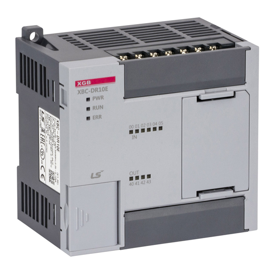
Chapter 1 Introduction 1.4 Product List Types Model Description Remark AC100~220V power supply, DC 24V input 6 point, relay output 4 point XBC-DR10E AC100~220V power supply, DC 24V input 8 point, relay output 6 point XBC-DR14E AC100~220V power supply, DC 24V input 12 point, relay output 8 point XBC-DR20E AC100~220V power supply, DC 24V input 18 point, relay output 12 point XBC-DR30E... -
Page 16: Terminology
Chapter 1 Introduction 1.5 Terminology The following table gives definition of terms used in this manual. Terms Definition Remark Example: A standard element that has a specified function which configures Expansion module, Module the system. Devices such as I/O board, which inserted onto the Special module, mother board. - Page 17 Chapter 1 Introduction Terms Definition Current flows from the switch to the PLC input terminal if an input signal turns on. Input Sensing Switch Current Sink Input Input Power Module Supply Sensing Input Optical Circuit Isolation Common − Current flows from the PLC input terminal to the switch after an input signal turns on.
-
Page 18: Chapter 2 Quick Start Guide
Chapter 2 Quick Start Guide Chapter 2 Quick Start Guide 2.1 Getting Started The quick start guide is intended to show a basic setup and programming of the XGB PLC. For more details on the features of the XGB PLC, refer to the rest of this manual. 2.1.1 Items Needed You will need the following items to set up your PLC for this example: 1. -
Page 19: Writing A Ladder Logic Program
Chapter 2 Quick Start Guide 5. Next select the CPU Type according to the chart below. Software CPU Type Selection Corresponding PLC Series XGB-XBCE E Type XGB-XBCS SU Type XGB-XBMH(V1) H Type XGB-XBCU U Type 2.3.2 Writing a Ladder Logic Program 1. - Page 20 Chapter 2 Quick Start Guide 2. Upon placing the contact, the Input Variable/Device window will appear. 3. Input P00 for the Variable/Device and click OK to insert the contact. 4. Next, select the Coil by clicking the icon or pressing F9. Pressing F9 will automatically insert the coil in the last slot of the rung.
- Page 21 Chapter 2 Quick Start Guide 6. Input P40 for the Variable/Device and click OK to insert the coil. 7. You have now written a simple Ladder Logic Program. This program will instruct the PLC to turn on the P40 output coil when P00 input is closed. XBC E-Type Main Unit Ver.
-
Page 22: Simulating Program Without Plc
Chapter 2 Quick Start Guide 2.3.3 Simulating Program Without PLC 1. The program can be simulated using XG5000 without needing to connect to a physical PLC. 2. To start the simulator, click either the taskbar icon shown below or Tools > Start Simulator. 3. - Page 23 Chapter 2 Quick Start Guide 4. The simulator allows you to control and test all functions of your ladder program. Double click the P00 contact to open the Change Value window. 5. Click OK to activate P00 which will cause P40 to turn on. XBC E-Type Main Unit Ver.
-
Page 24: Installation And Wiring Of Plc
Chapter 2 Quick Start Guide 2.4 Installation and Wiring of PLC 2.4.1 Connect Power Wiring 1. We are going to wire PLC and test program using PLC hardware. a. Connect power and I/O wiring to PLC according to the drawing below. b. -
Page 25: Writing Program To Plc
Chapter 2 Quick Start Guide e. Next, connect the PLC to your computer using the Comm. 1 port and cable. PMC-310S Programming Cable 2.5 Writing Program to PLC 1. Return to XG5000 and the test program we have written. 2. Open the connection settings by clicking: Online > Connection Settings XBC E-Type Main Unit Ver. - Page 26 Chapter 2 Quick Start Guide 3. This will show the Connection Settings Window. Since we are using an E-type PLC in this example, set Type to RS232C and Depth to Local. XG5000 software will automatically detect the PC port where the PLC is connected. 4.
- Page 27 Chapter 2 Quick Start Guide 6. Since the PLC was not running when we wrote the program to it, XG5000 will prompt to reset the PLC. Click OK. 7. To reconnect with the PLC click Online > Connect. 8. To run the PLC with its new program, click Online > Change Mode > Run. XBC E-Type Main Unit 2-10 Ver.
- Page 28 Chapter 2 Quick Start Guide 9. You can now test the program by closing the switch connected to P00 which will cause output P40 to turn on. XBC E-Type Main Unit 2-11 Ver. 1...
-
Page 29: Chapter 3 Installation And Wiring
Chapter 3 Installation and Wiring Chapter 3 Installation and Wiring 3.1 Safety Instructions Warning Design protection circuitry based on individual machine operation to protect the machine and operator in the event of a PLC failure or external power quality issue. ... - Page 30 Chapter 3 Installation and Wiring 3.1.1 Safety Instructions when designing PLC system Warning Install protection circuit on the exterior of PLC to protect the whole control system from any error in external power or PLC module. Any abnormal output or operation may cause serious problem in safety of the whole system.
- Page 31 Chapter 3 Installation and Wiring Caution I/O signal or communication line shall be wired at least 100mm away from a high-voltage cable or power line. If not, it may cause abnormal output or operation. Caution Use PLC only in the environment specified in PLC manual or general standard of data sheet.
- Page 32 Chapter 3 Installation and Wiring 3.1.2 Safety Instructions when wiring Warning Prior to wiring, be sure that power of PLC and external power is turned off. If not, electric shock or damage on the product may occur. Before PLC system is powered on, be sure that all terminal covers are securely closed.
- Page 33 Chapter 3 Installation and Wiring 3.1.3 Safety Instructions for test-operation or repair Caution Prior to installing or disassembling the module, switch off all external power, including PLC power. If not, electric shock or abnormal operation may occur. Keep any wireless installations or cell phone at least 30cm away from PLC.
-
Page 34: Power Budget
Chapter 3 Installation and Wiring 3.2 Power Budget Name Purpose ① 5VDC Module Logic Bus Internal power supply to power expansion modules. ② External Aux. 24VDC Supply External Auxiliary 24VDC supply 3.2.1 Internal DC5V Power Calculation LSIS PLCs supply power to expansion modules and option cards through a 5VDC internal bus. The rated output varies according to PLC model as shown in the table below. - Page 35 Chapter 3 Installation and Wiring Example calculation: Item Model Number Current Supply Current XBC-DN20E 600mA Current Draw XBO-DC04A 80mA Slot 0 Module XBO-DA02A 150mA Slot 1 Module Totals 230mA Current Required 370mA Current Remaining 1) Internal Current Consumption (DC 5V) (Unit : ㎃) Type Model...
- Page 36 Chapter 3 Installation and Wiring 2) If using on-board auxiliary DC24V supply of the main unit a. Do not connect DC24V of several power supplies in parallel. It may cause the destruction of a module. b. If a power module exceeds the DC24V output capacity, supply DC24V externally as presented below.
-
Page 37: Names Of Part And Function
Chapter 3 Installation and Wiring 3.3 Names of Part and Function “E” Type ⑧ ③ ⑦ ① ⑪ ⑪ ⑥ ⑩ ② ④ ⑨ Name Description ▪ Input indicator LED Input indicator LED ① ▪ Mini-DIN, 6-pin ② Comm. Port 1 RS-232C 1 channel ▪... -
Page 38: Dimension (Unit: Mm)
Chapter 3 Installation and Wiring 3.4 Dimension (Unit: mm) XBC-DR10/14E, XBC-DN10/14E, XBC-DP10/14E XBC-DR20/30E, XBC-DN20/30E, XBC-DP20/30E XBC E-Type Main Unit 3-10 Ver. 1... -
Page 39: Plc Mounting
Chapter 3 Installation and Wiring 3.5 PLC Mounting Use caution in handling Use PLC in accordance to general specification listed in manual. Improper use, may cause electric shock, fire, malfunction, or damage of product. Warning Module must be mounted to hook for fixation properly before its fixation. The module may be damaged from over-applied force. - Page 40 Chapter 3 Installation and Wiring b. In case of installing at panel i. You can install XBG compact type main unit on panel directly using screw holes and M4 type screws Panel #8 (2-Ø4.5mm) screw hole XBC E-Type Main Unit 3-12 Ver.
- Page 41 Chapter 3 Installation and Wiring 2. Module equipment location Keep the following distance between module and other components for ventilation and easy detachment and attachment. 3. PLC mounting orientation a. For proper ventilation, install with the PLC vents facing up and down. XBC E-Type Main Unit 3-13 Ver.
- Page 42 Chapter 3 Installation and Wiring b. Do not install in any orientation other than vertical as shown above. 4. Distance from other device To avoid radiated electrical noise or heat, keep the distance between PLC and powered devices and cabling at least 4 in. (100mm) from the front. 100mm or above XBC E-Type Main Unit...
-
Page 43: Wiring Guidelines
Chapter 3 Installation and Wiring For equipment installed next to PLC: 2in. (50mm) or more Minimum 2in. (50mm) Minimum 2in. (50mm) 3.6 Wiring Guidelines Warning When wiring, disconnect the external power. If all external power is not disconnected, electrical shock or equipment damage may occur. ... -
Page 44: Wiring General Specifications
Chapter 3 Installation and Wiring 3.6.1 Wiring General Specifications 1. Do not use a ferrule with the XGB terminal strip. Ring and Fork terminals or stranded wire are acceptable. 2. Terminal strip torque should be 42 - 58 N/cm (3.7 – 5.1 in/lb). Cable specification mm (AWG) Types of external... - Page 45 Chapter 3 Installation and Wiring 2. If using on-board DC24V supply of the main unit a. Do not connect DC24V of multiple power supplies in parallel. Permanent damage to the power supplies may occur. b. On-board power supply of main unit is 24VDC, 0.2A, 4.8W. c.
-
Page 46: A/C Power Input
Chapter 3 Installation and Wiring 3.6.3 A/C Power Input 1. 4A fuse for AC power input is recommended. 2. AC110V/ DC24V cables should not be installed within 4in. (100mm) from main circuit cable (high voltage/high current) and I/O signal cable. 3. -
Page 47: Digital I/O Module Notices
Chapter 3 Installation and Wiring 3.6.5 Digital I/O Module Notices 1. For digital input, there are two types: current sink input and current source input. 2. The number of maximum simultaneous input contact points varies according to module type. It depends on the input voltage and ambient temperature. -
Page 48: Precautions For High Speed Wiring
Chapter 3 Installation and Wiring 3.6.6 Precautions for high speed wiring Take care to the eliminate noise when wiring, especially for High-speed pulse input. 1. Use twisted pair shielded cable, ground shield at one end only. Grounding at control system ground point is preferred. -
Page 49: Ground Wiring
Chapter 3 Installation and Wiring 3.6.8 Ground Wiring 1. The PLC contains noise suppression, so it can be used without any separate grounding if there is a large amount of noise. However, if grounding is required, please refer to the following. 2. -
Page 50: Caution In Handling
Chapter 3 Installation and Wiring 3.6.9 Caution in handling • Don’t drop product. • Don’t disassemble the PLC or modules. No user serviceable parts inside. • In case of wiring, make sure foreign substance not to enter upper part of module. 1. -
Page 51: Main Unit Digital I/O Specifications
Chapter 3 Installation and Wiring 3.7 Main Unit Digital I/O Specifications 3.7.1 General I/O Specifications General Specifications Cable and Terminals 26 - 16 AWG (0.14 - 1.5 mm ); Cu wire; Terminal block (M3 X 6 screw) Torque 5.2 in/lb (0.58 N/m) Input Side Terminals (Top) RS232C Receive Data RS232C Transmit Data... -
Page 52: Xbc-Dr10E 4 Point Relay Output
Chapter 3 Installation and Wiring 3.7.2 XBC-DR10E 4 point relay output XBC E-Type Main Unit 3-24 Ver. 1... - Page 53 Chapter 3 Installation and Wiring Input Specifications Input point 6 point, 1 COM Insulation method Photo-coupler isolation Rated input voltage DC24V Rated input current 4mA (Point 0-3: 7mA) Operation voltage range DC20.4~28.8V (within ripple rate 5%) On voltage / On current DC19V or higher / 3mA or higher Off voltage / Off current DC6V or lower / 1mA or lower...
-
Page 54: Xbc-Dn10E 4 Point Transistor Output
Chapter 3 Installation and Wiring 3.7.3 XBC-DN10E 4 point transistor output XBC E-Type Main Unit 3-26 Ver. 1... - Page 55 Chapter 3 Installation and Wiring Input Specifications Input point 6 point, 1 COM Insulation method Photo-coupler insulation Rated input voltage DC24V Rated input current 4mA (point 0-3: 7mA) Operation voltage range DC20.4~28.8V (within ripple rate 5%) On voltage / On current DC19V or higher / 3mA or higher Off voltage / Off current DC6V or lower / 1mA or lower...
-
Page 56: Xbc-Dr14E 6 Point Relay Output
Chapter 3 Installation and Wiring 3.7.4 XBC-DR14E 6 point relay output XBC E-Type Main Unit 3-28 Ver. 1... - Page 57 Chapter 3 Installation and Wiring Input Specifications Input point 8 point, 1 COM Insulation method Photo-coupler insulation Rated input voltage DC24V Rated input current 4mA (point 0-3: 7mA) Operation voltage range DC20.4~28.8V (within ripple rate 5%) On voltage / On current DC19V or higher / 3mA or higher Off voltage / Off current DC6V or lower / 1mA or lower...
-
Page 58: Xbc-Dn14E 6 Point Transistor Output
Chapter 3 Installation and Wiring 3.7.5 XBC-DN14E 6 point transistor output XBC E-Type Main Unit 3-30 Ver. 1... - Page 59 Chapter 3 Installation and Wiring Input Specifications Input point 8 point, 1 COM Insulation method Photo-coupler insulation Rated input voltage DC24V Rated input current 4mA (point 0-3: 7mA) Operation voltage range DC20.4~28.8V (within ripple rate 5%) On voltage / On current DC19V or higher / 3mA or higher Off voltage / Off current DC6V or lower / 1mA or lower...
-
Page 60: Xbc-Dr20E 8 Point Relay Output
Chapter 3 Installation and Wiring 3.7.6 XBC-DR20E 8 point relay output XBC E-Type Main Unit 3-32 Ver. 1... - Page 61 Chapter 3 Installation and Wiring Input Specifications Input point 8 point, 1 COM Insulation method Photo-coupler insulation Rated input voltage DC24V Rated input current 4mA (point 0-3: 7mA) Operation voltage range DC20.4~28.8V (within ripple rate 5%) On voltage / On current DC19V or higher / 3mA or higher Off voltage / Off current DC6V or lower / 1mA or lower...
-
Page 62: Xbc-Dn20E 8 Point Transistor Output
Chapter 3 Installation and Wiring 3.7.7 XBC-DN20E 8 point transistor output XBC E-Type Main Unit 3-34 Ver. 1... - Page 63 Chapter 3 Installation and Wiring Input Specifications Input point 8 point, 1 COM Insulation method Photo-coupler insulation Rated input voltage DC24V Rated input current 4mA (point 0-3: 7mA) Operation voltage range DC20.4~28.8V (within ripple rate 5%) On voltage / On current DC19V or higher / 3mA or higher Off voltage / Off current DC6V or lower / 1mA or lower...
-
Page 64: Xbc-Dr30E 12 Point Relay Output
Chapter 3 Installation and Wiring 3.7.8 XBC-DR30E 12 point relay output XBC E-Type Main Unit 3-36 Ver. 1... - Page 65 Chapter 3 Installation and Wiring Input Specifications Input point 8 point, 1 COM Insulation method Photo-coupler insulation Rated input voltage DC24V Rated input current 4mA (point 0-3: 7mA) Operation voltage range DC20.4~28.8V (within ripple rate 5%) On voltage / On current DC19V or higher / 3mA or higher Off voltage / Off current DC6V or lower / 1mA or lower...
-
Page 66: Xbc-Dn30E 12 Point Transistor Output
Chapter 3 Installation and Wiring 3.7.9 XBC-DN30E 12 point transistor output XBC E-Type Main Unit 3-38 Ver. 1... - Page 67 Chapter 3 Installation and Wiring Input Specifications Input point 8 point, 1 COM Insulation method Photo-coupler insulation Rated input voltage DC24V Rated input current 4mA (point 0-3: 7mA) Operation voltage range DC20.4~28.8V (within ripple rate 5%) On voltage / On current DC19V or higher / 3mA or higher Off voltage / Off current DC6V or lower / 1mA or lower...
-
Page 68: Communications Specifications
Chapter 3 Connection Configuration 3.8 Communications Specifications 3.8.1 Built-in Serial Communication Interface (Cnet) Built-in serial communication is used to connect between the main unit and external devices. Further details can be found in the XGB Cnet I/F Manual. 3.8.2 Communication Ports Comm. -
Page 69: Comm. Port 1 Connection
Chapter 3 Connection Configuration Item Comm. Port 1 Specifications Comm. Port 2 Specifications Serial communication method RS-232C RS-232C/RS-485 Selectable Modem connection function Data bit 7 or 8 Data type Stop bit 1 or 2 Parity None (fixed) Even/Odd/None Synchronization type Asynchronous type Asynchronous type 1200/2400/4800/9600/19200/... -
Page 70: Comm. Port 2 Rs-232C Connection
Chapter 3 Connection Configuration Comm. Port 1 to PC with XG5000 for Programming Comm. Port 1 to HMI LS HMI or 3rd Party HMI. Operator interface (HMI) compatibility is dependent on operator interface (HMI) drivers provided by operator interface manufacturers 3.8.4 Comm. -
Page 71: Comm. Port 2 Rs-485
Chapter 3 Connection Configuration 2. Communication method for Comm. Port 2 is selectable between RS-232C and RS-485 in the XG5000 programming software. Comm. Port 2, RS-232C/RS-485 Selection in XG5000 Programming Software 3.8.5 Comm. Port 2 RS-485 1. RS-485 uses two wires for communication. Comm. -
Page 72: Chapter 4 Cpu Specifications
Chapter 4 CPU Specifications Chapter 4 CPU Specifications 4.1 General Specifications Items Specification Reference 0 ~ 55 °C Ambient Temp. −25 ~ +70 °C Storage Temp. Ambient humidity 5 ~ 95%RH (Non-condensing) Storage humidity 5 ~ 95%RH (Non-condensing) Occasional vibration Frequency Acceleration Amplitude... -
Page 73: Performance Specifications
Chapter 4 CPU Specifications 4.2 Performance Specifications XGB compact type CPU (XBC-Dx10/14/20/30E). Items Specifications Remark Program control method Fixed scan time, constant scan Scan synchronous batch processing method (Refresh method), I/O control method Directed by program instruction Program language Ladder Diagram, Instruction List Basic Number of instructions... - Page 74 Chapter 4 CPU Specifications Specifications (“E” type) XBC-DR10E XBC-DR14E XBC-DR20E XBC-DR30E Items Remark XBC-DN10E XBC-DN14E XBC-DN20E XBC-DN30E XBC-DP10E XBC-DP14E XBC-DP20E XBC-DP30E 250mA 280mA 350mA 470mA Internal consumption current 180mA 190mA 200mA 210mA 180mA 190mA 200mA 210mA 330g 340g 450g 465 g Weight 313g 315g...
-
Page 75: Data Backup Time
Chapter 4 CPU Specifications 4.3 Data Backup Time When RTC module is not installed in main unit, data is kept by super capacitor. Type Data backup time Remark With super-capacitor 5 Days At normal temperature 77°F “E” type (25°C) RTC module installed 3 Years Super capacitor will be recharged when power is on for over 30 minutes. -
Page 76: Program Instruction
Chapter 4 CPU Specifications 4.4 Program Instruction 4.4.1 Program execution methods 1. Cyclic operation method (Scan). This is a basic program proceeding method of PLC that performs the operation repeatedly for the prepared program from the beginning to the last step, which is called ‘program scan’. -
Page 77: Operation Processing During Momentary Power Failure
Chapter 4 CPU Specifications 2. Interrupt operation (Cycle time, Internal device). This is the method that stops the normal program operation and carries out the operation processing which corresponds to interrupt program immediately in case that there occurs the status to process emergently during PLC program execution. -
Page 78: Scan Time
Chapter 4 CPU Specifications Remark 1) Momentary power failure? This means the supply voltage at power condition designated by PLC is lowered below the allowable variable range for a short time (some ms ~ some dozens ms). This interruption is called ‘momentary power failure’. - Page 79 Chapter 4 CPU Specifications The main unit executes the scan in the following order. A user can estimate the control performance of a system constructed from the following calculation. ③I/O data Refresh ④Network Service ②System check & Task processing ⑤ XG5000 Service Ladder Scan Ladder Scan Program...
-
Page 80: Memory
Chapter 4 CPU Specifications 3. Scan time monitor a. Scan time can be monitored 『Online』-『PLC Information』-『Performance』. b. Scan time is save in special relay (F) area as follows. i. F0050: max. value of scan time (unit: 0.1ms) ii. F0051: min. value of scan time (unit: 0.1ms) iii. - Page 81 Chapter 4 CPU Specifications Area per device Device features Description “E” type Image area to save the state of I/O device. P0000 ~ P127f After reading the input module state, saves it in the Physical I/O “P” corresponding P area and sends P area Data saving the operation result to output module.
-
Page 82: Classifications Of Devices
Chapter 4 CPU Specifications 4.5.2 Classifications of devices Devices are classified into bit device and word device, based on expression method and operand processing method. 1. Bit device a. Available to express the bit without a ‘.’ (dot) when used in basic instructions as LOAD or OUT. -
Page 83: Auxiliary Relay M
Chapter 4 CPU Specifications As shown above, the P Area image is updated prior to the program scan. After the program logic is solved, the P Area Image is again updated. When the P Area image is updated prior to the next program scan, the output status from the end of the previous scan is also updated. -
Page 84: Data Types And Application Methods
Chapter 4 CPU Specifications 4.6 Data Types and Application Methods 4.6.1 Data types 4.6.2 Bit data (Bit) Bit data displays On/Off with 1 bit like contact or coil, or is processed by 1 bit unit inside the memory without I/O. 1. -
Page 85: Nibble / Byte Data (Nibble/Byte)
Chapter 4 CPU Specifications Here, Word device number is displayed in decimal and bit number in hexadecimal. For example, in order to express D0010’s bit number 1, set D0010.1. Similarly, D0011’s 10 bit is to be specified as D0011.A, as seen below. -
Page 86: Word Data (Word)
Chapter 4 CPU Specifications b. Word device: takes 4 or 8 bits from word device’s bit contact used as operand. When specified bit contact is used as the source and 4 or 8 bits is taken from specified contact, the bit which exceeds the applicable word unit will be processed as 0. Like above, if specified bit contact is used as the destination, the data exceeding the word will be lost. -
Page 87: Double Word Data (Dword)
Chapter 4 CPU Specifications 2. Bit device The bit device is expressed with its lowest digit (Digits expressed in hexadecimal – position to display bit) taken out and will be designated as word data. P00010 MOV H1234 P0000 P0000 1 word data of P0000 specified 4.6.5 Double word data (DWORD) Double word data is 32-bit numeric data. -
Page 88: Real Data (Real, Lreal)
Chapter 4 CPU Specifications 2. Bit device Like the expression of word data, the bit device is expressed with its lowest digit taken out, using the data of (Specified device number) and (Specified device number + 1) as double word data. P00010 DMOV 1234 P0001 2-point data (word) such as P0001, P0002 is the object... - Page 89 Chapter 4 CPU Specifications 3. Floating decimal point operation error : Exception (operation error) supported in IEEE754 standard Flag Designation Condition of Operation Error Remarks Incorrect operation F00570 If operation result is not correct due to limit of expression range error latch F00571 Underflow latch...
-
Page 90: String Data
Chapter 4 CPU Specifications 4.6.7 String data Among application instructions, string related instructions use the data type of number, alphabet, special sign, etc. to save in ASCII code. String data up to NULL code (h00) is regarded as one string row. And the maximum length of a string row is 32 bytes (including NULL). -
Page 91: Configuration Diagram Of Data Memory
Chapter 4 CPU Specifications 4.7 Configuration Diagram of Data Memory 4.7.1 Data areas ** K2600 through K2559 Area reserved for special functions (High Speed Counter). DO NOT use these K addresses in regular program. XBC E-Type Main Unit 4-20 Ver. 1... -
Page 92: Data Latch
Chapter 4 CPU Specifications 4.7.2 Data latch When PLC stops and restarts, the data required for operation or data occurred during operation, will be lost by default. If you want to keep and use that data, data latch can be used. It is possible to use a certain area of some data device as latch area by parameter setting. - Page 93 Chapter 4 CPU Specifications 2. Data latch area operation a. The method to delete the latched data is as below. i. latch 1, latch 2 clear operation by XG5000 ii. write by Program (initialization program recommended) iii. write ‘0’ FILL from XG5000 monitor mode. For keep or reset (clear) operation of latch area data according to PLC operation, please refer to the below table.
- Page 94 Chapter 4 CPU Specifications c. Latch 1, 2 area is cleared by『Online』-『Clear PLC』. 3. Data initialization Using the Memory Delete function, the memory of all device shall be cleared as ‘0’. To set the data value at the beginning according to system, please use the initialization task. a.
-
Page 95: Chapter 5 Programming Concepts
Chapter 5 Programming Concepts Chapter 5 Programming Concepts 5.1 Program Execution 5.1.1 Configuration of program All functional elements needed to execute a certain control process are called a ‘program’. The program is stored in the built-in RAM mounted on a CPU module or flash memory of a external memory module. The following table shows the classification of the program. - Page 96 Chapter 5 Programming Concepts 1. Scan program a. Function i. This program performs the operation repeatedly from 0 step to last step in order to process the signal that is repeatedly regularly every scan. ii. When the execution condition of the interrupt by task interrupt or interrupt module when execution the program is met, the current program stops and performs the applicable interrupt program.
-
Page 97: Interrupt
Chapter 5 Programming Concepts 5.1.3 Interrupt Example of interrupt setting is as shown below. Interrupt source Interrupt name priority Task No. Program Initializing Interrupt 0_ Cycle time 1 Interrupt 1_cycle time Cycle time 1 External Interrupt 2_external External Internal device Interrupt 3_internal Internal Cycle time 2... - Page 98 Chapter 5 Programming Concepts 1. How to write an interrupt program Generate the task in the project window of XG5000 as below and add the program to be executed by each task. For further information, please refer to XG5000 user’s manual. (Interrupt program may be created when XG5000 is not connected with PLC.) a.
- Page 99 Chapter 5 Programming Concepts c. Click right button of mouse at registered task and select『Add Item』-『Program』. d. Make the initializing program. In initializing program, INIT_DONE instruction must be made. If not, Scan program is not executed. XBC E-Type Main Unit Ver.
- Page 100 Chapter 5 Programming Concepts 2. How to write the Cycle interrupt program Add the task in the project window of XG5000 as below and add the program to be performed by each task. For further information, please refer to XG5000 user’s manual. (Interrupt program may be created when XG5000 is not connected with PLC.) a.
- Page 101 Chapter 5 Programming Concepts c. Task type Classification Description Remark Character, number Task name Make Task name. available “2” is the highest Priority Set the priority of task. (2~7) priority number. Set the Task number. • Cycle time task (0 ~ 7): 8 Task number •...
- Page 102 Chapter 5 Programming Concepts e. Register the Program name and Program description. The program window is displayed to write task program. g. It is displayed in project window. XBC E-Type Main Unit Ver. 1...
- Page 103 Chapter 5 Programming Concepts 3. Task type Task type and function is as follows. Type I/O task Cycle time task Internal device task (Interrupt task) (Interval task) (Single task) Spec. “E” type Max. Task number Cyclic (setting up to max. Internal device Start condition Rising or falling edge of main unit’s...
- Page 104 Chapter 5 Programming Concepts c. Processing delay time i. There are some causes for Task Program processing delay as shown below. Please consider this when writing the program and setting task priority. Task detection delay (Refer to detailed description of each task.) II.
- Page 105 Chapter 5 Programming Concepts b. Cyclic task processing i. Executes the corresponding cyclic task program per setting time interval (execution cycle) c. When using cyclic task program i. When cyclic task program is currently executing or waiting to execute, if the command to execute the same task program occurs, the new task will be ignored.
- Page 106 Chapter 5 Programming Concepts 6. I/O task program processing It described the I/O task program processing. (“E” type: P000~P003) a. Items to be set in Task i. Set the execution condition and priority to the task being executed. Check the task no.
- Page 107 Chapter 5 Programming Concepts 7. Internal device task program processing Below describes the processing method of an internal device task program which extended the task (start condition) of the task program from contact point to device as execution range. a. Items to be set in Task i.
- Page 108 Chapter 5 Programming Concepts 8. Verification of task program a. Is the task setting proper? i. If task occurs frequently more than needed or several tasks occur in one scan, scan time may lengthen or be irregular. If it is not possible to change the task setting, verify maximum scan time.
- Page 109 Chapter 5 Programming Concepts Scan started Scan program stopped New scan started (Initial operation started) Scan program Program 1 10ms_Cycle time Program 2 Internal device_M000 Program 3 External I/O_P000 Time 6 7 8 10 12 20 22 24 25 30 32 34 Process per time Time (㎳) Process...
-
Page 110: Operation Mode
Chapter 5 Programming Concepts 5.2 Operation Mode For operation mode of the CPU module, there are 3 types such as RUN mode, STOP mode and DEBUG mode. This describes the operation processing of each operation mode. 5.2.1 RUN mode Executes program operation normally. RUN mode first scan start Initialize data area Check Program for Errors... -
Page 111: Stop Mode
Chapter 5 Programming Concepts 5.2.2 STOP mode Stop state without Program operation. It is available to transmit the program through XG5000 only in Remote STOP mode. 1. Processing at Mode Change: Clear the output image area and execute output update. 2. -
Page 112: Scan Watchdog Timer
Chapter 5 Programming Concepts a. Remote mode conversion is available only in the state of ‘Remote Enabled: On’, ‘Mode switch: Stop’. i. When changing the Remote ‘RUN’ mode to ‘STOP’ by switch, operate the switch as follows. (STOP) RUN STOP. Warning When changing Remote RUN mode to RUN mode by switch, PLC operation continues the operation without interruption. -
Page 113: Timer Processing
Chapter 5 Programming Concepts 5.2.5 Timer processing The XGB series use up count timer. There are 5 timer instructions such as on-delay (TON), off-delay (TOFF), integral (TMR), monostable (TMON), and re-triggerable (TRTG) timer. The measuring range of 100msec timer is 0.1 ~ 6553.5 seconds, 10msec timer is 0.01 ~ 655.35 seconds, and that of 1msec timer is 0.001 ~ 65.53 seconds. - Page 114 Chapter 5 Programming Concepts 2. Off delay timer The current value of timer set as preset value and the timer output relay is turned on when the input condition of TOFF instruction turns on. When the input condition is turned off, the current value starts to decrease.
- Page 115 Chapter 5 Programming Concepts 4. Monostable timer In general, its operation is same as off-delay timer. However, the change of input condition is ignored while the timer is operating (decreasing). When current value reaches preset value the timer output relay is turned off and current value is cleared. Timer input condition t2 t3...
-
Page 116: Counter Processing
Chapter 5 Programming Concepts 5.2.6 Counter processing The counter counts the rising edges of pulses driving its input signal and counts once only when the input signal is switched from off to on. XGB series have 4 counter instructions such as CTU, CTD, CTUD, and CTR. The followings shows brief information for counter operation. - Page 117 Chapter 5 Programming Concepts ii. When the reset input is turned On, the current value is cleared as 0. d. Ring counter i. The current value is increased with the rising edge of the counter input signal, and the counter output contact (Cxxx) is turned on when the current value reaches the preset value.
-
Page 118: Chapter 6 Instruction And Flag List
Chapter 6 Instruction and Flag List Chapter 6 Instruction and Flag List 6.1 Classifications of Instructions Classification Instructions Details Remarks Contact Point LOAD, AND, OR related Instructions Unite AND LOAD, OR LOAD, MPUSH, MLOAD, MPOP Reverse Master Control MCS, MCSCLR OUT, SET, RST, 1 Scan Output Instruction, Output Reverse Output Basic... -
Page 119: Basic Instructions
Chapter 6 Instruction and Flag List 6.2 Basic Instructions 6.2.1 Contact Point Instruction Details Classification Designations Name Page LOAD Normally Open Contact 6-37 LOAD NOT Normally Closed Contact AND Normally Open Contact 6-39 AND NOT AND Normally Closed Contact OR Normally Open Contact 6-40 OR NOT OR Normally Closed Contact... - Page 120 Chapter 6 Instruction and Flag List 6.2.5 Output Instruction Details Classification Designations Name Page Mnemonic Output Contact OUT NOT Mnemonic Reverse Output Contact 6-52 OUTP Output on Rising Input Output OUTN Output on Falling Input Set Contact Point Output 6-56 Reset Contact Point Output 6-57 Output Reverse on Input Condition...
- Page 121 Chapter 6 Instruction and Flag List 6.2.10 Counter instruction Details Classification Designations Name Page Count Down 6-79 Count Up 6-81 Counter CTUD Count Up/Count Down 6-83 Ring Counter 6-86 6.3 Application Instruction 6.3.1 Data transfer instruction Details Classification Designations Name Page Move 16 bits...
- Page 122 Chapter 6 Instruction and Flag List 6.3.2 BCD/BIN conversion instruction Details Classification Designations Name Page BCD to Decimal Conversion Binary Coded BCDP Rising Edge BCD to Decimal Conversion Decimal 6-100 (BCD) DBCD Double Word BCD to Decimal Conversion Conversion DBCDP Rising Edge Double Word BCD to Decimal Conversion BCD4 Nibble Binary to BCD Conversion...
- Page 123 Chapter 6 Instruction and Flag List 6.3.3 Data type conversion instruction Details Classification Designations Name Page Integer to Real 16 Bits I2RP Rising Edge Integer to Real Integer/Real 6-109 Integer to Long Real Conversion I2LP Rising Edge Integer to Long Real Double Integer to Real D2RP Rising Edge Double Integer to Real...
- Page 124 Chapter 6 Instruction and Flag List 6.3.4 Comparison instruction Details Classification Designations Name Page Compare Unsigned CMPP Rising Edge Compare Compare 6-117 DCMP Double Word Compare Using Flags DCMPP Rising Edge Double Word Compare CMP4 Compare Nibble CMP4P Rising Edge Compare Nibble Unsigned 4/8 6-118 Bits Compare...
- Page 125 Chapter 6 Instruction and Flag List Details Classification Designations Name Page GDEQ Group Double Word Equal To GDEQP Group Double Word Equal To Rising Edge GDGT Group Double Word Greater Than GDGTP Group Double Word Greater Than Rising Edge GDLT Group Double Word Less Than GDLTP Group Double Word Less Than Rising Edge...
- Page 126 Chapter 6 Instruction and Flag List Designations Details Classification Name /Mnemonic Page < 16-Bit Less Than <= 16-Bit Less Than or Equal To 16-Bit <> 16-Bit Not Equal To Data 16-Bit Equal To Compare > 16-Bit Greater Than >= 16-Bit Greater Than or Equal To 6-122 <...
- Page 127 Chapter 6 Instruction and Flag List Designations Details Classification Name /Mnemonic Page $< String Less Than $<= String Less Than or Equal To $<> String Not Equal To String 6-126 Compare String Equal To $> String Greater Than $>= String Greater Than or Equal To G<...
- Page 128 Chapter 6 Instruction and Flag List Designations Details Classification Name /Mnemonic Page <3 3 Variable 16-Bit Greater Than <=3 3 Variable 16-Bit Less Than or Equal To <>3 3 Variable 16-Bit Not Equal To Three 16-Bit Data Compare 3 Variable 16-Bit Equal To >3 3 Variable 16-Bit Greater Than >=3...
- Page 129 Chapter 6 Instruction and Flag List 6.3.5 Increase/Decrease instruction Designations/ Details Classification Name Mnemonic Page BIN Data Increase INCP BIN Data Increase Rising Edge 6-134 DINC BIN Data Double Increase Binary (BIN) DINCP BIN Data Double Increase Rising Edge Data Increase BIN Data Decrease Decrease (Signed)
- Page 130 Chapter 6 Instruction and Flag List 6.3.6 Rotation Function Details Classification Designations Name Page Rotate Left ROLP Rotate Left Rising Edge Rotate to Left 6-140 DROL Double Rotate Left DROLP Double Rotate Left Rising Edge ROL4 Nibble Rotate Left ROL4P Nibble Rotate Left Rising Edge 4/8 Bits 6-141...
- Page 131 Chapter 6 Instruction and Flag List 6.3.7 Move instruction Details Classification Designations Name Page BSFT Bit Shift Bits Move 6-148 BSFTP Bit Shift Rising Edge BSFL Bit Shift Left BSFLP Bit Shift Left Rising Edge Move to 6-149 Higher Bit DBSFL Double Bit Shift Left DBSFLP...
- Page 132 Chapter 6 Instruction and Flag List 6.3.8 Exchange instruction Details Classification Designations Name Page XCHG Exchange XCHGP Exchange Rising Edge Data 6-157 Exchange DXCHG Double Exchange DXCHGP Double Exchange Rising Edge Group GXCHG Group Exchange Data 6-158 GXCHGP Group Exchange Rising Edge Exchange Higher/Lower SWAP...
- Page 133 Chapter 6 Instruction and Flag List 6.3.9 BIN operation instruction Details Classification Designations Name Page Integer ADDP Add Rising Edge Addition 6-161 DADD Double Add (Signed) DADDP Double Add Rising Edge Subtract Integer SUBP Subtract Rising Edge Subtraction 6-162 DSUB Double Subtract (Signed) DSUBP...
- Page 134 Chapter 6 Instruction and Flag List Details Classification Designations Name Page DIVU Divide Unsigned DIVUP Divide Unsigned Rising Edge Integer Division 6-168 DDIVU Double Divide Unsigned (Unsigned) DDIVUP Double Divide Unsigned Rising Edge RADD Real Add RADDP Real Add Rising Edge Real Number 6-169 Addition...
- Page 135 Chapter 6 Instruction and Flag List 6.3.10 BCD operation instruction Details Classification Designations Name Page ADDB BCD Add ADDBP BCD Add Rising Edge BCD Addition 6-176 DADDB Double BCD Add DADDBP Double BCD Add Rising Edge SUBB BCD Subtract SUBBP BCD Subtract Rising Edge 6-177 Subtraction...
- Page 136 Chapter 6 Instruction and Flag List 6.3.11 Logic operation instruction Details Classification Designations Name Page WAND Word AND WANDP Word AND Rising Edge Logic 6-181 Multiplication DWAND Double Word AND DWANDP Double Word AND Rising Edge Word OR WORP Word OR Rising Edge Logic Addition 6-183 DWOR...
- Page 137 Chapter 6 Instruction and Flag List 6.3.12 Data process instruction Details Classification Designations Name Page BSUM Bit Summary BSUMP Bit Summary Rising Edge Bit Check 6-201 DBSUM Double Bit Summary DBSUMP Double Bit Summary Rising Edge BRST Bit Reset Bit Reset 6-202 BRSTP Bit Reset Rising Edge...
- Page 138 Chapter 6 Instruction and Flag List Details Classification Designations Name Page Search Min Word MINP Search Min Word Rising Edge Min. Value 6-214 Search DMIN Search Min Double Word DMINP Search Min Double Word Rising Edge Word Summary SUMP Word Summary Rising Edge 6-216 DSUM Double Word Summary...
- Page 139 Chapter 6 Instruction and Flag List 6.3.13 Data table process instruction Details Classification Designations Name Page FIWR File Write Data 6-226 Write FIWRP File Write Rising Edge FIFRD First File Read First-input Data 6-228 Read FIFRDP First File Read Rising Edge FILRD Last File Read Last-Input...
- Page 140 Chapter 6 Instruction and Flag List 6.3.15 String Process instruction Details Classification Designations Name Page BINDA Binary to Decimal ASCII Convert to BINDAP Binary to Decimal ASCII Rising Edge Decimal 6-232 ASCII DBINDA Double Binary to Decimal ASCII Cord DBINDAP Double Binary to Decimal ASCII Rising Edge BINHA Binary to Hex ASCII...
- Page 141 Chapter 6 Instruction and Flag List Details Classification Designations Name Page Binary to String STRP Binary to String Rising Edge Convert BIN16/32 to 6-245 String DSTR Double Binary to String DSTRP Double Binary to String Rising Edge String to Binary VALP String to Binary Rising Edge Convert String...
- Page 142 Chapter 6 Instruction and Flag List 6.3.16 Special function instruction Details Classification Designations Name Page Sine SIN Operation 6-258 SINP Sine Rising Edge ASIN Arc-sine ARCSIN 6-259 Operation ASINP Arc-sine Rising Edge Cosine 6-260 Operation COSP Cosine Rising Edge ACOS Arc-cosine ARCCOS 6-261...
- Page 143 Chapter 6 Instruction and Flag List 6.3.17 Data control instruction Details Classification Designations Name Page LIMIT Limit Output LIMITP Limit Output Rising Edge Limit 6-271 Control DLIMIT Double Word Limit Output DLIMITP Double Word Limit Output Rising Edge DZONE Dead Zone DZONEP Dead Zone Rising Edge Dead-zone...
- Page 144 Chapter 6 Instruction and Flag List 6.3.18 Time related instruction Details Classification Designations Name Page Date/Time DATERD Date Read 6-280 Data DATERDP Date Read Rising Edge Read Date/Time DATEWR Date Write Data 6-281 DATEWRP Date Write Rising Edge Write ADDCLK Add Clock Time Data 6-282...
- Page 145 Chapter 6 Instruction and Flag List 6.3.20 Loop instruction Details Classification Designations Name Page Start Loop 6-288 Loop NEXT Next Loop Instruction 6-289 BREAK Break Loop 6.3.21 Flag instruction Details Classification Designations Name Page Set Carry Flag Carry Flag Set, 6-290 Reset Clear Carry Flag...
- Page 146 Chapter 6 Instruction and Flag List 6.3.23 Interrupt related instruction Details Classification Designations Name Page Execute All Tasks All Task Interrupt 6-300 Setting Do Not Execute All Tasks Individual Task Execute Specific Task Interrupt 6-301 Setting Stop Specific Task 6.3.24 Sign reversion instruction Details Classification Designations Name...
- Page 147 Chapter 6 Instruction and Flag List 6.4 F area Control Instruction Details Classification Designations Name Page FSET Flag Bit Set 6-305 Flag Control FRST Flag Bit Reset 6-306 Instruction FWRITE Flag Word Set 6-307 6.5 Bit Control Instruction Details Classification Designations Name Page Bit of Word...
- Page 148 Chapter 6 Instruction and Flag List 6.7 Special Relay (F) List “U” Type Word Variables Function Description _SYS_STATE Mode and state Indicates PLC mode and operation State. F0000 _RUN Run state. F0001 _STOP Stop Stop state. F0002 _ERROR Error Error state. F0003 _DEBUG F0004...
- Page 149 Chapter 6 Instruction and Flag List Word Variable Function Description F0028 _BPRM_ER Basic parameter Basic parameter error. F0029 _IOPRM_ER IO parameter I/O configuration parameter error. Special module parameter is F002A _SPPRM_ER Special module parameter Abnormal. Communication module Communication module parameter F002B _CPPRM_ER F002~3...
- Page 150 Chapter 6 Instruction and Flag List Word Variable Function Description _USER_CLK User Clock Clock available for user setting. F0100 _USR_CLK0 Setting scan repeat On/Off as much as set scan Clock 0. F0101 _USR_CLK1 Setting scan repeat On/Off as much as set scan Clock 1. F0102 _USR_CLK2 Setting scan repeat...
- Page 151 Chapter 6 Instruction and Flag List Word Variable Function Description Clock data (Hundred year/week) F0056 _HUND_WK Hundred year/week Supported when using RTC option module _FPU_INFO F0570 _FPU_LFLAG_I F0571 _FPU_LFLAG_U F0572 _FPU_LFLAG_O F0573 _FPU_LFLAG_Z F0574 _FPU_LFLAG_V F057 F057A _FPU_FLAG_I F057B _FPU_FLAG_U F057C _FPU_FLAG_O F057D...
- Page 152 Chapter 6 Instruction and Flag List Word Variable Function Description F104 _IO_DEER0 Module Detach 0 error Main base module Detach error. F120 _IO_RWER0 Module RW 0 error Main base module read/write error. F128 _IO_IFER_0 Module IF 0 error Main base module interface error. F140 _AC_FAIL_CNT F142...
- Page 153 Chapter 6 Instruction and Flag List 6.8 Guide for Instruction Details For each instruction, you will find the following tables: Data Area Table: Area Available Flag Instruction Step Error Zero Carry P M K Z D.x R.x U N D R nst.
-
Page 154: Contact Point Instruction
Chapter 6 Instruction Details Instruction Details 6.9 Contact point Instruction 6.9.1 LOAD, LOAD NOT, LOADP, LOADN Area Available Flag Instruction Step Error Zero Carry P M K Z D.x R.x U N D R nst. (F110) (F111) (F112) LOAD S O O O O O O O O LOAD NOT LOADP S O O O O O O O O... - Page 155 Chapter 6 Instruction Details 3) Program Example (1) If Input Condition of P00020 is On, P00060 Output will be On, and at the same time P00061 Output will be Off. While D00020.3 changes 01 for 1 scan, P00062 Output will be On, and while D00020.3 changes 10 for 1 scan, P00063 Output will be On.
- Page 156 Chapter 6 Instruction Details 6.9.2 AND, AND NOT, ANDP, ANDN Area Available Flag Instruction Step Error Zero Carry P M K Z D.x R.x U N D R nst. (F110) (F111) (F112) O O O O O O O O AND NOT ANDP O O O O O O O O...
- Page 157 Chapter 6 Instruction Details 6.9.3 OR, OR NOT, ORP, ORN Area Available Flag Instruction Step Error Zero Carry P M K Z D.x R.x U N D R nst. (F110) (F111) (F112) O O O O O O O O OR NOT O O O O O O O O OR S...
- Page 158 Chapter 6 Instruction Details [Example 4-1] Forward/Reverse Operation of Motor [LOAD, AND, OR, OUT] 1) Operation Press push button PB1 to rotate motor clockwise, or PB2 to rotate motor counterclockwise. Rotation direction can be changed even if the motor is not stopped. Press push button PB0 to stop the motor.
- Page 159 Chapter 6 Instruction Details *1) Clockwise Motor Operation Clockwise motor operation and interlock ‘P00032 P00061’ setting P00032 P00061 *2) Counterclockwise Motor Operation Counterclockwise motor operation and interlock ‘P00031 P00060’ setting P00031 P00060 Remark < Latching Circuit > P00060 P00031 P00030 P00060 (1) P00031 if On makes Output P00060 On, which makes self-used input A contact P00060 On and keeps the On state until P00030 signal is input.
-
Page 160: Union Instruction
Chapter 6 Instruction Details 6.10 Union Instruction 6.10.1 AND LOAD Area Available Flag Instruction Step Error Zero Carry P M K Z D.x R.x U N D R nst. (F110) (F111) (F112) AND LOAD AND LOAD B Block A Block 1) Function (1) It performs AND Operation of A Block and B Block. - Page 161 Chapter 6 Instruction Details 3) References In case Circuit Block is series-connected continuously, program input is of 2 types as follows. M00000 M00002 M00004 M00006 M00008 P00050 M00001 M00003 M00005 M00007 M00009 AND LOAD times unlimited AND LOAD times limited LOAD LOAD M00000...
- Page 162 Chapter 6 Instruction Details 6.10.2 OR LOAD Area Available Flag Instruction Step Error Zero Carry P M K Z D.x R.x U N D R nst. (F110) (F111) (F112) OR LOAD A block OR LOAD B block 1) OR LOAD (1) Performs OR operation of A Block and B Block to get the result.
- Page 163 Chapter 6 Instruction Details 3) References When Circuit Block is series-connected continuously, program input is of 2 types as follows. M00000 M00001 P00006 M00002 M00003 M00004 M00005 M00006 M00007 M00008 M00009 OR LOAD times unlimited OR LOAD times unlimited LOAD M00000 LOAD M00000...
- Page 164 Chapter 6 Instruction Details 6.10.3 MPUSH, MLOAD, MPOP Area Available Flag Instruction Step Error Zero Carry P M K Z D.x R.x U N D R nst. (F110) (F111) (F112) MPUSH MLOAD MPOP MPUSH MLOAD MPOP 1) MPUSH, MLOAD, MPOP (1) Makes Ladder’s Multiple Diverge available.
- Page 165 Chapter 6 Instruction Details 2) References [Ladder Program] P00020 P00022 P00023 P00024 P00021 P00060 00000 P00025 P00061 P00026 P00062 P00027 P00063 P00028 P00064 P00029 P00065 P0002A P00066 00027 [Mnemonic Program] Step Mnemonic Operand LOAD P00200 0000 MPUSH 0001 P00021 0002 MPUSH 0003 P00022...
- Page 166 Chapter 6 Instruction Details 6.11 Reversion Instruction 6.11.1 NOT Area Available Flag Instruction Step Error Zero Carry P M K Z D.x R.x U N D R nst. (F110) (F111) (F112) 1) NOT (1) NOT reverses the previous result. (2) If Reverse Instruction (NOT) is used: A contact circuit is reversed to B contact circuit, B contact circuit to A contact circuit, and series-connected circuit is reversed to parallel-connected circuit, parallel-connected circuit to series-connected circuit for the left circuit of Reverse Instruction.
- Page 167 Chapter 6 Instruction Details 6.12 Master Control Instruction 6.12.1 MCS, MCSCLR Area Available Flag Instruction Step Error Zero Carry P M K Z D.x R.x U N D R nst. (F110) (F111) (F112) MCSCLR MCSCLR MCSCLR Operand Description Data Type 0 ~ 7 for XGB WORD(0~15) 1) MCS, MCSCLR...
- Page 168 Chapter 6 Instruction Details [Example 8.4] Circuit with Common LINE [MCS, MCSCLR] Use master control (MCS, MCSCLR) Instruction for programming since the circuit state of PLC Program will not be as shown below. [Relay Circuit] Manual Auto P00020 P00021 P00024 P00023 M00061 P00060...
- Page 169 Chapter 6 Instruction Details 6.13 Output Instruction 6.13.1 OUT, OUT NOT, OUTP, OUTN Area Available Flag Instruction Step Error Zero Carry P M K Z D.x R.x U N D R nst. (F110) (F111) (F112) O O O OUT NOT OUTP O O O OUTN...
- Page 170 Chapter 6 Instruction Details 3) Program Example (1) OUTP Example: Performs OUTP Instruction when input contact P00032 changes Off to On. [Ladder Program] [Mnemonic Program] P00032 M00002 Step Mnemonic Operand LOAD P00032 OUTP M00002 M00002 P00060 LOAD M00002 P00060 P00060 P00060 Self-holding where 1 scan On is output as P00060...
- Page 171 Chapter 6 Instruction Details (2) OUTN Example: Performs D Instruction when input contact P00032 changes Off to On. [Ladder Program] [Mnemonic Program] P00033 M00003 Step Mnemonic Operand P00033 LOAD M00003 OUTN M00003 P00061 LOAD M00003 P00061 P00061 P00061 Self-holding where 1 scan On is output as P00061 ·...
- Page 172 Chapter 6 Instruction Details [Example 8.3] Output On/Off Operation [OUTP/OUTN] (1) Operation Press push button PB0 to make Output On first and press again to make Output Off. Whenever PB0 is pressed, Output is repeatedly On and Off. (2) System Diagram Digital input module Digital output module P00000...
- Page 173 Chapter 6 Instruction Details 6.13.2 SET Area Available Flag Instruction Step Error Zero Carry P M K Z D.x R.x U N D R nst. (F110) (F111) (F112) O O O Operand Description Data Type Contact to keep On state / Word device’s bit contact 1) SET (1) If input condition is On, output is kept On even when specified output contact is kept On to make Input Off.
- Page 174 Chapter 6 Instruction Details 6.13.3 RST Area Available Flag Instruction Step Error Zero Carry P M K Z D.x R.x U N D R nst. (F110) (F111) (F112) O O O O O O Operand Description Data Type Contact to keep Off state / Word device’s bit contact 1) RST (1) If input condition is On, output is kept Off even when specified output contact is kept Off to make Input Off.
- Page 175 Chapter 6 Instruction Details [Example 8.4] Precautions against Power Failure Differences between P & K areas & Set/Reset Operation (1) Differences between Input/Output Relay(P) and Keep Relay(K) All the following sequences are of self-keep circuit with the same operation. However, if Output is cut off while On and then powered again, its output state will be different.
- Page 176 Chapter 6 Instruction Details 6.13.4 FF Area Available Flag Instruction Step Error Zero Carry P M K Z D.x R.x U N D R nst. (F110) (F111) (F112) O O O Operand Description Data Type Bit device’s contact / Word device’s bit contact 1) FF (1) Reverses specified device’s state when input contact changes Off ...
- Page 177 Chapter 6 Instruction Details 6.14 Sequence/Last-input Preferred Instruction 6.14.1 SET Syy.xx Area Available Flag Instruction Step Error Zero Carry P M K Z D.x R.x U N D R nst. (F110) (F111) (F112) Syy.xx SET Syy.xx Operand Description Data Type As S device contact, yy is for group number, xx for step number.
- Page 178 Chapter 6 Instruction Details [Example 8.5] Sequence Control [SET S] Process 2 is executed only after Process 1 is complete and Process 1 is executed again after Process 3 is complete in applicable sequence. [Ladder Program] Start S00.01 Process 3 End Process 1 End S00.02 Process condition 2 S00.02 output...
- Page 179 Chapter 6 Instruction Details 6.14.2 OUT Syy.xx Area Available Flag Instruction Step Error Zero Carry P M K Z D.x R.x U N D R nst. (F110) (F111) (F112) Syy.xx OUT Syy.xx Operand Description Data Type As S device contact, yy is for group number, xx for step number. Syy.xx Group Number is available 0~127, and step number 0~99 1) OUT Syy.xx (Subsequent Input Preferred)
- Page 180 Chapter 6 Instruction Details 6.15 End Instruction 6.15.1 END Area Available Flag Instruction Step Error Zero Carry P M K Z D.x R.x U N D R nst. (F110) (F111) (F112) 1) END (1) Displays Program End. (2) Returns to 0000 Step after END Instruction is processed. (3) END Instruction should be input last in program.
- Page 181 Chapter 6 Instruction Details 6.16 Non-process Instruction 6.16.1 NOP Area Available Flag Instruction Step Error Zero Carry P M K Z D.x R.x U N D R nst. (F110) (F111) (F112) No Ladder Symbol. (used only in Mnemonic) 1) NOP (1) It means No Operation Instruction which has no effect on operation result of applicable circuit until then.
- Page 182 Chapter 6 Instruction Details 6.17 Timer Instructions 6.17.1 Timer Types and Functionality 1) Basic Characteristics (1) Three time increment multipliers are available (100ms, 10ms, 1ms). The assignment for the three timer ranges are accessed in the Basic Settings in the XG5000 software. Navigate to the Project Tree > Parameters >...
- Page 183 Chapter 6 Instruction Details (6) If Reset Instruction is used to reset Timer, be sure to input in the same format as used in Timer format shown below; If TON T0001[Z000] D00010[Z003] is used, Timer format used in reset coil should be T0001[Z000], or program error will occur in XG5000.
- Page 184 Chapter 6 Instruction Details 6.17.2 TON Area Available Flag Instruction Step Error Zero Carry P M K Z D.x R.x U N D R nst. (F110) (F111) (F112) O O O Input Condition Operand Description Data Type Timer Contact to use WORD stands for Timer’s setting value.
- Page 185 Chapter 6 Instruction Details [Time Chart] ← → t = 20 sec P00020 [Example 8.6] Flicker Circuit [TON] (1) Operation: uses 2 timers to blink Output.. [System Diagram] Output module Input Module P00006 P00002 Start Program LAMP [Time Chart] P00002 P00060 [Program] P00020...
- Page 186 Chapter 6 Instruction Details 6.17.3 TOFF Area Available Flag Instruction Step Error Zero Carry P M K Z D.x R.x U N D R nst. (F110) (F111) (F112) TOFF O O O Input Condition Contact Operand Description Data Type Timer Contact to use WORD Stands for Timer’s setting value.
- Page 187 Chapter 6 Instruction Details [Example 8.7] Conveyer Control [TON, TOFF] (1) Operation It makes several conveyers operate (A → B → C) and stop (C → B → A) in sequence. [System Diagram] Input Module Ouput Module P00020 P00060 Conveyor Start Motor Motor...
- Page 188 Chapter 6 Instruction Details 6.17.4 TMR Area Available Flag Instruction Step Error Zero Carry P M K Z D.x R.x U N D R nst. (F110) (F111) (F112) O O O Input Condition Contact Operand Description Data Type Timer Contact to use WORD Stands for timer’s setting value.
- Page 189 Chapter 6 Instruction Details [Example 8.8] Tools’s Life Alarm Circuit [TMR] (1) Operation It measures application time of tool such as machining center and outputs alarm to exchange tools. (2) System Diagram Digital input module Digital input module P00006 P00002 Program Sensor (Measures tool...
- Page 190 Chapter 6 Instruction Details 6.17.5 TMON Area Available Flag Instruction Step Error Zero Carry P M K Z D.x R.x U N D R nst. (F110) (F111) (F112) TMON O O O Input condition contact TMON TMON Operand Description Data Type Timer Contact to use WORD Stands for Timer’s setting value.
- Page 191 Chapter 6 Instruction Details [Time Chart] P00023 P00020 Setting Value T0000 Setting Time P00061 [Example 8.9] Signal Vibration-Proof Circuit [TMON] (1) Operation Keeps variation of passing signal of object with irregular speed (limit switch) so to get a stable signal. (2) System Diagram Digital input module Limit switch signal in...
- Page 192 Chapter 6 Instruction Details 6.17.6 TRTG Area Available Flag Instruction Step Error Zero Carry P M K Z D.x R.x U N D R nst. (F110) (F111) (F112) TRTG O O O Input Condition Contact Point TRTG TRTG Operand Description Data Type Timer Contact to use WORD...
- Page 193 Chapter 6 Instruction Details [Time chart] P00020 t=5 sec P00065 (Decreased) [Example] Error Detect Circuit of Returning Equipment [TRTG] (1) Operation Detects missing item on conveyor based on a known time between detection of items. When item is detected on Input P0002, Timer T0005 begins counting down from the preset and Bit Output M0002 is turned ON starting the process.
- Page 194 Chapter 6 Instruction Details 6.18 Counter Instruction 6.18.1 Characteristics of Counter 1) Basic Characteristics (1) Counter increases/decreases present value whenever rising edge of pulse is input. If setting value is reached, it makes Output On. (2) Counter has 4 instructions based on counter functions. Instruction Designations Operation characteristics...
- Page 195 Chapter 6 Instruction Details (4) Counter value setting available device (Operand available) is integers of P, M, K, U, D, R, etc. with index functions available. However, at this moment available index range is Z0 ~ Z3. (5) If Reset Instruction is used to reset Counter, be sure to input in the same format used in Counter format as shown below;...
- Page 196 Chapter 6 Instruction Details 6.18.2 CTD Area Available Flag Instruction Step Error Zero Carry P M K Z D.x R.x U N D R nst. (F110) (F111) (F112) O O O Count Input Reset Signal Operand Description Data Type Counter contact to use WORD Set Value (0 ~ 65535) WORD...
- Page 197 Chapter 6 Instruction Details 2) Program Example (1) If P00030 contact is On 5 times, P00060 Output will be On when present value is counted down to “0”. (2) If P00031 contact is On, Output will be Off, and present value will be setting value. [Ladder Program] P00030 C0010...
- Page 198 Chapter 6 Instruction Details 6.18.3 CTU Area Available Flag Instruction Step Error Zero Carry P M K Z D.x R.x U N D R nst. (F110) (F111) (F112) O O O Count Input Reset Signal Operand Description Data Type Counter contact to use WORD Setting value (0 ~ 65535) WORD...
- Page 199 Chapter 6 Instruction Details 2) Program Example (1) If counted up to P00030, contact with present value identical to set value, P00060 Output will be On. (2) If P00031 contact is On, Output will be Off and present value will be set to “0”. [Ladder Program] P00030 C0010...
- Page 200 Chapter 6 Instruction Details 6.18.4 CTUD Area Available Flag Instruction Step Error Zero Carry P M K Z D.x R.x U N D R nst. (F110) (F111) (F112) O O O O O O O CTUD O O O O O O O O O O Input Count...
- Page 201 Chapter 6 Instruction Details 2) Program Example (1) If present value is the same as set value with count up to P00030 contact, P00060 Output will be On. (2) It will be counted Down due to P00031 contact’s Rising edge of the pulse. (3) If Reset Condition is met, Output will be Off, and counter’s present value “0”.
- Page 202 Chapter 6 Instruction Details (3) Program FOOO99 CTUD C0001 P00030 P00031 C0005 C0001 FOOO99 CTUD C0002 P00030 P00031 C0005 C0002 FOOO99 CTUD C0003 P00030 P00031 C0005 C0003 FOOO99 CTUD C0004 P00030 P00031 C0005 C0004 FOOO99 CTUD C0005 P00030 P00031 C0005 C0005 C0001 P00060...
- Page 203 Chapter 6 Instruction Details 6.18.5 CTR Area Available Flag Instruction Step Error Zero Carry P M K Z D.x R.x U N D R nst. (F110) (F111) (F112) O O O Count Input Reset Signal ( R ) Operand Description Data Type Counter contact to use WORD...
- Page 204 Chapter 6 Instruction Details 6.19 Data transfer Instruction 6.19.1 MOV, MOVP, DMOV, DMOVP Area Available Flag Instruction Step Error Zero Carry( P M K Z D.x R.x U N D R nst. (F110) (F111) F112) MOV(P) O O O O O O O O O O O O DMOV(P) O O O...
- Page 205 Chapter 6 Instruction Details (2) Whenever P00001 is on, data (hF0F0 FF33) of P0002, P0001 is moved to P0006, P0005 double word by MOVP instruction. P00001 DMOVP P0001 P0005 P0002 P0001 1 1 1 1 0 0 0 0 1 1 1 1 0 0 0 0 1 1 1 1 1 1 1 1 0 0 1 1 0 0 1 1 P0006 P0005 1 1 1 1 0 0 0 0 1 1 1 1 0 0 0 0 1 1 1 1 1 1 1 1 0 0 1 1 0 0 1 1...
- Page 206 Chapter 6 Instruction Details 6.19.2 MOV4, MOV4P, MOV8, MOV8P Area Available Flag Instruction Step Error Zero Carry P M K Z D.x R.x U N D R nst. (F110) (F111) (F112) MOV4(P) O O O O O O O MOV8(P) O O O MOV4, MOV8 MOV4P,...
- Page 207 Chapter 6 Instruction Details 3) MOV8 D00003.A D10.3 (1) If Source Device is of word, and data to transfer is out of the specified word range, the range exceeded will be disregarded and filled with 0 in Destination. 4) Program Example Where 4-Bit Data from P00004 is transferred to D0.2 ~ D0.5 by MOV4P Instruction whenever Input Signal P00020 is On.
- Page 208 Chapter 6 Instruction Details 6.19.3 CMOV, CMOVP, DCMOV, DCMOVP Area Available Flag Instruction Step Error Zero Carry P M K Z D.x R.x U N D R nst. (F110) (F111) (F112) CMOV(P) O O O O O O O O O O O O DCMOV(P) O O O O O O...
- Page 209 Chapter 6 Instruction Details 3) Program Example (1) If Input P00020 is On, it takes P00002 word data’s 1’s complement to transfer to P0006. P00020 CMOV P0002 P0006 1 Word S 0 1 1 0 1 0 1 1 0 0 1 0 1 0 1 1 ( P0002) D 1 0 0 1 0 1 0 0 1 1 0 1 0 1 0 0 CMOV execution...
- Page 210 Chapter 6 Instruction Details 6.19.4 GMOV, GMOVP Area Available Flag Instruction Step Error Zero Carry P M K Z D.x R.x U N D R nst. (F110) (F111) (F112) O O O O O O O O O O O O GMOV(P) O O O O O O...
- Page 211 Chapter 6 Instruction Details 6.19.5 FMOV, FMOVP Area Available Flag Instruction Step Error Zero Carry P M K Z D.x R.x U N D R nst. (F110) (F111) (F112) O O O O O O O O O O O O FMOV(P) O O O O O O...
- Page 212 Chapter 6 Instruction Details 6.19.6 BMOV, BMOVP Area Available Flag Instruction Step Error Zero Carry P M K Z D.x R.x U N D R nst. (F110) (F111) (F112) O O O O O O O O O O O O BMOV(P) O O O O O O O...
- Page 213 Chapter 6 Instruction Details 2) Program Example Whenever Input Signal P00030 is On, 4-bit from the 0 bit in P0002 area will be saved in P0006 starting from P0063 bit. P00030 BMOVP P0002 P0006 h0304 . . . P0002 . . . P0006 XBC E-Type Main Unit 6-96...
- Page 214 Chapter 6 Instruction Details 6.19.7 GBMOV, GBMOVP Area Available Flag Instruction Step Error Zero Carry P M K Z D.x R.x U N D R nst. (F110) (F111) (F112) O O O O O O O O O O O O O O O O O O O O O O...
- Page 215 Chapter 6 Instruction Details 6.19.8 RMOV, RMOVP, LMOV, LMOVP Area Available Flag Instruction Step Error Zero Carry P M K Z D.x R.x U N D R nst. (F110) (F111) (F112) O O O O O O O O O O O O RMOV(P) LMOV(P) O O O...
- Page 216 Chapter 6 Instruction Details 6.19.9 $MOV, $MOVP Area Available Flag Instruction Step Error Zero Carry P M K Z D.x R.x U N D R nst. (F110) (F111) (F112) O O O O O O O O O O O $MOV(P) 2~18 O O O...
-
Page 217: Conversion Instruction
Chapter 6 Instruction Details 6.20 Conversion Instruction 6.20.1 BCD, BCDP, DBCD, DBCDP Area Available Flag Instruction Step Error Zero Carry P M K Z D.x R.x U N D R nst. (F110) (F111) (F112) O O O O O O O O O O O O BCD(P) DBCD(P) - Page 218 Chapter 6 Instruction Details 2) DBCD (Binary-Coded Decimal) (1) It converts specified (S+1,S) device’s BIN Data (0~h05F5E0FF) to BCD so to save in D+1 and D respectively. S+1 (Higher places) S (Lower places) 0 0 0 0 0 1 0 1 1 1 1 1 0 1 0 1 1 1 1 0 0 0 0 0 1 1 1 1 1 1 1 1 S : h05F5EOFF Convert to BCD D : BCD 99999999...
- Page 219 Chapter 6 Instruction Details [Example 8.12] Counter’s (Timer) External Output of Present Value [BCD, BMOV] (1) Operation If the warehouse keeps 30 products in stock, conveyer will stop, and the number kept in stock will be displayed. (2) System Diagram Digital Input Module Digital Output Module P00003...
- Page 220 Chapter 6 Instruction Details 6.20.2 BCD4, BCD4P, BCD8, BCD8P Area Available Flag Instruction Step Error Zero Carry P M K Z D.x R.x U N D R nst. (F110) (F111) (F112) BCD4(P) O O O O O O O BCD8(P) O O O BCD4, BCD8 BCD4P, BCD8P...
- Page 221 Chapter 6 Instruction Details 6.20.3 BIN, BINP, DBIN, DBINP Area Available Flag Instruction Step Error Zero Carry P M K Z D.x R.x U N D R nst. (F110) (F111) (F112) BIN(P) O O O O O O O O O O O O DBIN(P) O O O O O O...
- Page 222 Chapter 6 Instruction Details 2) DBIN (Double Binary) (1) It converts specified S+1,S device’s BCD data( 0~99999999) to BIN data and it is saved in D+1,D. S : BCD 99999999 S+1 (Higher 4 places) S (Lower 4 places) 1 0 0 1 1 0 0 1 1 0 0 1 1 0 0 1 1 0 0 1 1 0 0 1 1 0 0 1 1 0 0 1 Covert to BIN 0 0 0 0 0 1 0 1 1 1 1 1 0 1 0 1 1 1 1 0 0 0 0 0 1 1 1 1 1 1 1 1...
- Page 223 Chapter 6 Instruction Details 6.20.4 BIN4, BIN4P, BIN8, BIN8P Area Available Flag Instruction Step Error Zero Carry P M K Z D.x R.x U N D R nst. (F110) (F111) (F112) BIN4(P) O O O O O O O BIN8(P) O O O BIN4, BIN8...
- Page 224 Chapter 6 Instruction Details 6.20.5 GBCD, GBCDP Area Available Flag Instruction Step Error Zero Carry P M K Z D.x R.x U N D R nst. (F110) (F111) (F112) O O O O O O O O O O O O GBCD(P) O O O O O O...
- Page 225 Chapter 6 Instruction Details 6.20.6 GBIN, GBINP Area Available Flag Instruction Step Error Zero Carry P M K Z D.x R.x U N D R nst. (F110) (F111) (F112) O O O O O O O O O O O O GBIN(P) O O O O O O...
-
Page 226: Convert Real Instruction
Chapter 6 Instruction Details 6.21 Convert Real Instruction 6.21.1 I2R, I2RP, I2L, I2LP Area Available Flag Instruction Step Error Zero Carry P M K Z D.x R.x U N D R nst. (F110) (F111) (F112) O O O O O O O O O O O O I2R(P) I2L(P) - Page 227 Chapter 6 Instruction Details 6.21.2 D2R, D2RP, D2L, D2LP Area Available Flag Instruction Step Error Zero Carry P M K Z D.x R.x U N D R nst. (F110) (F111) (F112) D2R(P) O O O O O O O O O O O O D2L(P) O O O O O O...
- Page 228 Chapter 6 Instruction Details 6.21.3 R2I, R2IP, R2D, R2DP Area Available Flag Instruction Step Error Zero Carry P M K Z D.x R.x U N D R nst. (F110) (F111) (F112) R2I(P) O O O O O O O O O O O O R2D(P) O O O O O O...
- Page 229 Chapter 6 Instruction Details 3) Error (1) When R2I Instruction is used and S specified Single Real Number is out of -32,768~32,767 range, operation error occurs. (2) When R2D Instruction is used and S specified Single Real Number is out of -2,147,483,648~2,147,483,647 range, operation error occurs.
- Page 230 Chapter 6 Instruction Details 6.21.4 L2I, L2IP, L2D, L2DP Area Available Flag Instruction Step Error Zero Carry P M K Z D.x R.x U N D R nst. (F110) (F111) (F112) L2I(P) O O O O O O O O O O O O L2D(P) O O O O O O...
- Page 231 Chapter 6 Instruction Details (2) If S+3,S+2,S+1,S specified Real Number’s value exceeds -2,147,483,648 ~ 2,147,483,647 range, operation error occurs. At this moment, the result of 2,147,483,647 will be saved if Real value is bigger than 2,147,483,647, and -2,147,483,648 will be saved if Real value is smaller than -2,147,483,648. (3) Value of below decimals will be omitted after rounding off the nearest integer.
- Page 232 Chapter 6 Instruction Details 6.21.5 R2L, R2LP Area Available Flag Instruction Step Error Zero Carry P M K Z D.x R.x U N D R nst. (F110) (F111) (F112) O O O O O O O O O O O O R2L(P) O O O O O O...
- Page 233 Chapter 6 Instruction Details 6.21.6 L2R, L2RP Area Available Flag Instruction Step Error Zero Carry P M K Z D.x R.x U N D R nst. (F110) (F111) (F112) O O O O O O O O O O O O L2R(P) O O O O O O...
-
Page 234: Output Terminal Compare Instruction
Chapter 6 Instruction Details 6.22 Output Terminal Compare Instruction (Unsigned) 6.22.1 CMP, CMPP, DCMP, DCMPP Area Available Flag Instruction Step Error Zero Carry P M K Z D.x R.x U N D R nst. (F110) (F111) (F112) S1 O O O O O O O O O O O O O O O CMP(P) DCMP(P) - Page 235 Chapter 6 Instruction Details 6.22.2 CMP4, CMP4P, CMP8, CMP8P Area Available Flag Instruction Step Error Zero Carry P M K Z D.x R.x U N D R nst. (F110) (F111) (F112) CMP4(P) S1 O O O O O O O CMP8(P) S2 O O O O O O O...
- Page 236 Chapter 6 Instruction Details 6.22.3 TCMP, TCMPP, DTCMP, DTCMPP Area Available Flag Instruction Step Error Zero Carry P M K Z D.x R.x U N D R nst. (F110) (F111) (F112) S1 O O O O O O O O O O O O O O O TCMP(P) S2 O O O O O O O O O O...
-
Page 237: Instruction
Chapter 6 Instruction Details 6.22.4 GX(P), GDX(P), (GEQ, GEQP, GGT, GGTP, GLT, GLTP, GGE, GGEP, GLE, GLEP, GNE, GNEP , GDEQ, GDEQP, GDGT, GDGTP, GDLT, GDLTP, GDGE, GDGEP, GDLE, GDLEP, GDNE, GDNEP) Area Available Flag Instruction Step Error Zero Carry Z D.x R.x nst. - Page 238 Chapter 6 Instruction Details 2) Program Example Operation Result h00FF D1000 D1100 D1200 1234 1234 D1001 D1101 5678 5678 D1002 D1102 5000 5000 D1006 D1106 7777 7777 D1007 D1107 4321 4321 If Input signal P0000 is On, it compares 8-word data and compared result h00FF is saved in D1200. P00000 D1000 D1100 D1200 8 XBC E-Type Main Unit...
- Page 239 Chapter 6 Instruction Details 6.23 Compare Instruction, Signed (Input Position*) 6.23.1 Compare (16-Bit: <, <=, <>, =, >, >= ) (32-Bit: D<, D<=, D<>, D=, D>, D>=) Area Available Flag Instruction Step Error Zero Carry Z D.x R.x (F110) (F111) (F112) S1 O (compare...
- Page 240 Chapter 6 Instruction Details b) Example: When Data Register D1000 >= D2000 (i.e. D1000=10; D2000=10) AND contact P00000 is On, ‘1500’ is then saved in P1600 (I/O Device) area. 3) OR x (16-Bit: <, <=, <>, =, >, >= ) (32-Bit: D<, D<=, D<>, D=, D>, D>=) a) Ladder Structure: If contacts C1 and C2 are On, OR if x comparision condition is true, coil CR1 will be On.
- Page 241 Chapter 6 Instruction Details 6.23.2 Real Compare (16-Bit: R<, R<=, R<>, R=, R>, R>= ) (32-Bit: L<, L<=, L<>,L=, L>, L>=) Area Available Flag Instruction Step Error Zero Carry Z D.x R.x (F110) (F111) (F112) S1 O (compare S2 O operators) 16-Bit 32-Bit...
- Page 242 Chapter 6 Instruction Details b) Example: When Data Register D1000 >= D2000 (i.e. D1000=10; D2000=10) AND contact P00000 is On , ‘1234’ is then saved in P1600 (I/O Device ) area. 3) OR x (16-Bit: R<, R<=, R<>, R=, R>, R>= ) (32-Bit: L<, L<=, L<>, L=, L>, L>=) a) Ladder Structure: If contacts C1 and C2 are On, OR if x comparision condition is true, coil CR1 wil be On.
- Page 243 Chapter 6 Instruction Details 6.23.3 String Compare ($<, $<=, $<>, $=, $>, $>=) Area Available Flag Instruction Step Error Zero Carry Z D.x R.x (F110) (F111) (F112) S1 O (compare S2 O operators) Operation Operation x Operators Name Condition Condition result result S1 ≥...
- Page 244 Chapter 6 Instruction Details b) Example: When Data Register D1000>=D2000 (i.e. D1000=’English’; D2000=’English’) AND contact P00000 is On, ‘1567’ is then saved in P1600 (I/O device) area. 3) OR x ($<, $<=, $<>, $=, $>, $>=) a) Ladder Structure: If contacts C1 and C2 are On, OR if x comparision condition is true, coil CR1 wil be On.
- Page 245 Chapter 6 Instruction Details 6.23.4 Group Compare (16-Bit: G<, G<=, G<>, G=, G>, G>= ) (32-Bit: DG<, DG<=, DG<>, DG=, DG>, L>=) Area Available Flag Instruction Step Error Zero Carry Z D.x R.x (F110) (F111) (F112) S1 O (compare S2 O operators) 16-Bit 32-Bit...
- Page 246 Chapter 6 Instruction Details b) Example: When the 8-word data groups D1000 to D1007 is equal to D1100 to D1107, Group Compare Input Signal is On and then ‘1300’ is saved in P1400. When ‘=’ comparing two groups, if any one value is not identical, Group Compare Input Signal will not turn On.
- Page 247 Chapter 6 Instruction Details 6.23.5 3-Word Compare (16-bit: <3, <=3, <>3, =3, >3, >=3) (32-bit: D<3, D<=3, D<>3, D=3, D>3, D>=3) Area Available Flag Instruction Step Error Zero Carry Z D.x R.x (F110) (F111) (F112) S1 O (compare S2 O operators) S3 O 16-Bit...
- Page 248 Chapter 6 Instruction Details b) Example: When Data Registers D1000 = D1200 = D1300 (i.e. D1000=100, D1200=100, and D1300=100) AND contact P00000 is On, ‘1234’ is saved in P1500 (I/O Device) area. OR x (16-bit: <3, <=3, <>3, =3, >3, >=3) (32-bit: D<3, D<=3, D<>3, D=3, D>3, D>=3) a) Ladder Structure: If contacts C1 and C2 are On, OR if x comparision condition is true, coil CR1 will be On.
- Page 249 Chapter 6 Instruction Details 6.23.6 Byte/Nibble Compare (Byte: 8<, 8<=, 8<>, 8=, 8>, 8>=) (Nibble: 4<, 4<=, 4<>, 4=, 4>, 4>=) Area Available Flag Instruction Step Error Zero Carry P M K Z D.x R.x U N D R nst. (F110) (F111) (F112)
- Page 250 Chapter 6 Instruction Details 2) AND x (Byte: 8=, 8>, 8<, 8>=, 8<=, 8<>) (Nibble: 4=, 4>, 4<, 4>=, 4<=, 4<>) a) Ladder Structure: If the contact C1 is on AND the x comparision condition is true, then coil CR1 will be On. Otherwise CR1 will be Off.
- Page 251 Chapter 6 Instruction Details 6.24 Increase/Decrease Instruction 6.24.1 INC, INCP, DINC, DINCP Area Available Flag Instruction Step Error Zero Carry P M K Z D.x R.x U N D R nst. (F110) (F111) (F112) INC(P) O O O O O -- O O O O O O DINC(P) Command...
- Page 252 Chapter 6 Instruction Details 6.24.2 INC4, INC4P, INC8, INC8P Area Available Flag Instruction Step Error Zero Carry P M K Z D.x R.x U N D R nst. (F110) (F111) (F112) INC4(P) O O O INC8(P) Command INC4, INC8 Command INC4P, INC8P means...
- Page 253 Chapter 6 Instruction Details 6.24.3 DEC, DECP, DDEC, DDECP Area Available Flag Instruction Step Error Zero Carry P M K Z D.x R.x U N D R nst. (F110) (F111) (F112) DEC(P) O O O O O O O O O O DDEC(P) Command DEC,...
- Page 254 Chapter 6 Instruction Details 6.24.4 DEC4, DEC4P, DEC8, DEC8P Area Available Flag Instruction Step Error Zero Carry P M K Z D.x R.x U N D R nst. (F110) (F111) (F112) DEC4(P) O O O DEC8(P) Command DEC4, DEC8 Command DEC4P, DEC8P means Operand...
- Page 255 Chapter 6 Instruction Details 6.24.5 INCU, INCUP, DINCU, DINCUP Area Available Flag Instruction Step Error Zero Carry P M K Z D.x R.x U N D R nst. (F110) (F111) (F112) INCU(P) O O O O O O O O O O DINCU(P) Command INCU,...
- Page 256 Chapter 6 Instruction Details 6.24.6 DECU, DECUP, DDECU, DDECUP Area Available Flag Instruction Step Error Zero Carry P M K Z D.x R.x U N D R nst. (F110) (F111) (F112) DECU(P) O O O O O O O O O O DDECU(P) Command DECU,...
-
Page 257: Rotation Instruction
Chapter 6 Instruction Details 6.25 Rotation Instruction 6.25.1 ROL, ROLP, DROL, DROLP Area Available Flag Instruction Step Error Zero Carry P M K Z D.x R.x U N D R nst. (F110) (F111) (F112) O O O O O O O O O O ROL(P) DROL(P) - Page 258 Chapter 6 Instruction Details 6.25.2 ROL4, ROL4P, ROL8, ROL8P Area Available Flag Instruction Step Error Zero Carry P M K Z D.x R.x U N D R nst. (F110) (F111) (F112) O O O ROL4(P) ROL8(P) O O O O O O O O O O O Command ROL4, ROL8...
- Page 259 Chapter 6 Instruction Details 6.25.3 ROR, RORP, DROR, DRORP Area Available Flag Instruction Step Error Zero Carry P M K Z D.x R.x U N D R nst. (F110) (F111) (F112) ROR(P) O O O O O O O O O O DROR(P) O O O O O O...
- Page 260 Chapter 6 Instruction Details 6.25.4 ROR4, ROR4P, ROR8, ROR8P Area Available Flag Instruction Step Error Zero Carry P M K Z D.x R.x U N D R nst. (F110) (F111) (F112) ROR4(P) O O O ROR8(P) O O O O O O O O O O O Command ROR4, ROR8...
- Page 261 Chapter 6 Instruction Details 6.25.5 RCL, RCLP, DRCL, DRCLP Area Available Flag Instruction Step Error Zero Carry P M K Z D.x R.x U N D R nst. (F110) (F111) (F112) RCL(P) O O O O O O O O O O DRCL(P) O O O O O O...
- Page 262 Chapter 6 Instruction Details 6.25.6 RCL4, RCL4P, RCL8, RCL8P Area Available Flag Instruction Step Error Zero Carry P M K Z D.x R.x U N D R nst. (F110) (F111) (F112) RCL4(P) O O O RCL8(P) O O O O O O O O O O O Command RCL4, RCL8...
- Page 263 Chapter 6 Instruction Details 6.25.7 RCR, RCRP, DRCR, DRCRP Area Available Flag Instruction Step Error Zero Carry P M K Z D.x R.x U N D R nst. (F110) (F111) (F112) RCR(P) O O O O O O O O O O DRCR(P) O O O O O O...
- Page 264 Chapter 6 Instruction Details 6.25.8 RCR4, RCR4P, RCR8, RCR8P Area Available Flag Instruction Step Error Zero Carry P M K Z D.x R.x U N D R nst. (F110) (F111) (F112) RCR4(P) O O O RCR8(P) O O O O O O O O O O O Command RCR4, RCR8...
-
Page 265: Move Instruction
Chapter 6 Instruction Details 6.26 Move Instruction 6.26.1 BSFT, BSFTP Area Available Flag Instruction Step Error Zero Carry P M K Z D.x R.x U N D R nst. (F110) (F111) (F112) St O O O BSFT(P) Ed O O O Command BSFT Command... - Page 266 Chapter 6 Instruction Details 6.26.2 BSFL, BSFLP, DBSFL, DBSFLP Area Available Flag Instruction Step Error Zero Carry P M K Z D.x R.x U N D R nst. (F110) (F111) (F112) BSFL(P) O O O O O O O O O O DBSFL(P) O O O O O O...
- Page 267 Chapter 6 Instruction Details 3) Program Example (1) For P1000=’h000F’, when P00000 is changed to On from Off status, it rotates 4 bit to the left bit by bit and ‘h00F0’ is saved in P1000’. P00000 BSFL P1000 XBC E-Type Main Unit 6-150 Ver.
- Page 268 Chapter 6 Instruction Details 6.26.3 BSFL4, BSFL4P, BSFL8, BSFL8P Area Available Flag Instruction Step Error Zero Carry P M K Z D.x R.x U N D R nst. (F110) (F111) (F112) BSFL4(P) O O O BSFL8(P) O O O O O O O O O O O Command BSFL4, BSFL8...
- Page 269 Chapter 6 Instruction Details 6.26.4 BSFR, BSFRP, DBSFR, DBSFRP Area Available Flag Instruction Step Error Zero Carry P M K Z D.x R.x U N D R nst. (F110) (F111) (F112) BSFR(P) O O O O O O O O O O DBSFR(P) O O O O O O...
- Page 270 Chapter 6 Instruction Details 6.26.5 BSFR4, BSFR4P, BSFR8, BSFR8P Area Available Flag Instruction Step Error Zero Carry P M K Z D.x R.x U N D R nst. (F110) (F111) (F112) BSFR4(P) O O O BSFR8(P) O O O O O O O O O O O Command BSFR4(P)
- Page 271 Chapter 6 Instruction Details 6.26.6 WSFT, WSFTP Area Available Flag Instruction Step Error Zero Carry P M K Z D.x R.x U N D R nst. (F110) (F111) (F112) O O O O O O O O O O WSFT(P) O O O O O O O O O O...
- Page 272 Chapter 6 Instruction Details 6.26.7 WSFL, WSFLP, WSFR, WSFRP Area Available Flag Instruction Step Error Zero Carry P M K Z D.x R.x U N D R nst. (F110) (F111) (F112) D1 O O O O O O O O O O WSFL(P) D2 O O O O O O...
- Page 273 Chapter 6 Instruction Details 6.26.8 SR Area Available Flag Instruction Step Error Zero Carry P M K Z D.x R.x U N D R nst. (F110) (F111) (F112) Db O O O O O O O O O O O O O O O O O O O O O...
- Page 274 Chapter 6 Instruction Details 6.27 Exchange Instruction 6.27.1 XCHG, XCHGP, DXCHG, DXCHGP Area Available Flag Instruction Step Error Zero Carry P M K Z D.x R.x U N D R nst. (F110) (F111) (F112) D1 O O O O O O O O O O XCHG(P) DXCHG(P)
- Page 275 Chapter 6 Instruction Details 6.27.2 GXCHG, GXCHGP Area Available Flag Instruction Step Error Zero Carry P M K Z D.x R.x U N D R nst. (F110) (F111) (F112) D1 O O O O O O O O O O GXCHG(P) D2 O O O O O O...
- Page 276 Chapter 6 Instruction Details 6.27.3 SWAP, SWAPP Area Available Flag Instruction Step Error Zero Carry P M K Z D.x R.x U N D R nst. (F110) (F111) (F112) SWAP(P) O O O O O O O Command SWAP Command SWAPP means SWAP...
- Page 277 Chapter 6 Instruction Details 6.27.4 GSWAP, GSWAPP Area Available Flag Instruction Step Error Zero Carry P M K Z D.x R.x U N D R nst. (F110) (F111) (F112) O O O O O O O GSWAP(P) O O O O O O O O GSWAP GSWAPP...
- Page 278 Chapter 6 Instruction Details 6.28 BIN Operation Instruction 6.28.1 ADD, ADDP, DADD, DADDP Area Available Flag Instruction Step Error Zero Carry P M K Z D.x R.x U N D R nst. (F110) (F111) (F112) S1 O O O O O O O O O O O O ADD(P) S2 O O O O O O O...
- Page 279 Chapter 6 Instruction Details 6.28.2 SUB, SUBP, DSUB, DSUBP Area Available Flag Instruction Step Error Zero Carry P M K Z D.x R.x U N D R nst. (F110) (F111) (F112) S1 O O O O O O O O O O O O SUB(P) S2 O O O O O O O O O O O O...
- Page 280 Chapter 6 Instruction Details 6.28.3 MUL, MULP, DMUL, DMULP Area Available Flag Instruction Step Error Zero Carry P M K Z D.x R.x U N D R nst. (F110) (F111) (F112) S1 O O O O O O O O O O O O MUL(P) S2 O O O O O O O O O O O O...
- Page 281 Chapter 6 Instruction Details 6.28.4 DIV, DIVP, DDIV, DDIVP Area Available Flag Instruction Step Error Zero Carry P M K Z D.x R.x U N D R nst. (F110) (F111) (F112) S1 O O O O O O O O O O O O DIV(P) S2 O O O O O O O O O O O O...
- Page 282 Chapter 6 Instruction Details 6.28.5 ADDU, ADDUP, DADDU, DADDUP Area Available Flag Instruction Step Error Zero Carry P M K Z D.x R.x U N D R nst. (F110) (F111) (F112) S1 O O O O O O O O O O O O ADDU(P) S2 O O O O O O O O O O O O...
- Page 283 Chapter 6 Instruction Details 6.28.6 SUBU, SUBUP, DSUBU, DSUBUP Area Available Flag Instruction Step Error Zero Carry P M K Z D.x R.x U N D R nst. (F110) (F111) (F112) S1 O O O O O O O O O O O O SUBU(P) S2 O O O O O O O O O O O O...
- Page 284 Chapter 6 Instruction Details 6.28.7 MULU, MULUP, DMULU, DMULUP Area Available Flag Instruction Step Error Zero Carry P M K Z D.x R.x U N D R nst. (F110) (F111) (F112) S1 O O O O O O O O O O O O MULU(P) S2 O O O O O O O O O O O O...
- Page 285 Chapter 6 Instruction Details 6.28.8 DIVU, DIVUP, DDIVU, DDIVUP Area Available Flag Instruction Step Error Zero Carry P M K Z D.x R.x U N D R nst. (F110) (F111) (F112) S1 O O O O O O O O O O O O DIVU(P) S2 O O O O O O O O O O O O...
- Page 286 Chapter 6 Instruction Details 6.28.9 RADD, RADDP, LADD, LADDP Area Available Flag Instruction Step Error Zero Carry P M K Z D.x R.x U N D R nst. (F110) (F111) (F112) S1 O O O O O O O O O O O O RADD(P) S2 O O O O O O O O O O O O...
- Page 287 Chapter 6 Instruction Details 6.28.10 RSUB, RSUBP, LSUB, LSUBP Area Available Flag Instruction Step Error Zero Carry P M K Z D.x R.x U N D R nst. (F110) (F111) (F112) S1 O O O O O O O O O O O O RSUB(P) S2 O O O O O O O O O O O O...
- Page 288 Chapter 6 Instruction Details 6.28.11 RMUL, RMULP, LMUL, LMULP Area Available Flag Instruction Step Error Zero Carry P M K Z D.x R.x U N D R nst. (F110) (F111) (F112) S1 O O O O O O O O O O O O RMUL(P) S2 O O O O O O O O O O O O...
- Page 289 Chapter 6 Instruction Details 6.28.12 RDIV, RDIVP, LDIV, LDIVP Area Available Flag Instruction Step Error Zero Carry P M K Z D.x R.x U N D R nst. (F110) (F111) (F112) S1 O O O O O O O O O O O O RDIV(P) S2 O O O O O O O O O O O O...
- Page 290 Chapter 6 Instruction Details 6.28.13 $ADD, $ADDP Area Available Flag Instruction Step Error Zero Carry P M K Z D.x R.x U N D R nst. (F110) (F111) (F112) S1 O O O O O O O O $ADD(P) S2 O O O O O O O O 4~18 O O O...
- Page 291 Chapter 6 Instruction Details 6.28.14 GADD, GADDP, GSUB, GSUBP Area Available Flag Instruction Step Error Zero Carry P M K Z D.x R.x U N D R nst. (F110) (F111) (F112) S1 O O O O O O O O O O O GADD(P) S2 O O O O O O O O O O O O...
- Page 292 Chapter 6 Instruction Details 2) GSUB (Group Subtract) (1) Saves the result of N word data from specified device S1 minus N word data from S2 respectively in N word data from specified device D. 1234 1111 S1+1 5555 S2+1 2222 3333 S1+(N-1)
- Page 293 Chapter 6 Instruction Details 6.29 BCD Operation Instruction 6.29.1 ADDB, ADDBP, DADDB, DADDBP Area Available Flag Instruction Step Error Zero Carry P M K Z D.x R.x U N D R nst. (F110) (F111) (F112) S1 O O O O O O O O O O O O ADDB(P) S2 O O O O O O O...
- Page 294 Chapter 6 Instruction Details 6.29.2 SUBB, SUBBP, DSUBB, DSUBBP Area Available Flag Instruction Step Error Zero Carry P M K Z D.x R.x U N D R nst. (F110) (F111) (F112) S1 O O O O O O O O O O O O SUBB(P) S2 O O O O O O O O O O O O...
- Page 295 Chapter 6 Instruction Details 6.29.3 MULB, MULBP, DMULB, DMULBP Area Available Flag Instruction Step Error Zero Carry P M K Z D.x R.x U N D R nst. (F110) (F111) (F112) S1 O O O O O O O O O O O O MULB (P) S2 O O O O O O O O O O O O...
-
Page 296: Instruction
Chapter 6 Instruction Details 6.29.4 DIVB, DIVBP, DDIVB, DDIVBP Area Available Flag Instruction Step Error Zero Carry P M K Z D.x R.x U N D R nst. (F110) (F111) (F112) S1 O O O O O O O O O O O O DIVB(P) S2 O O O O O O O O O O O O... - Page 297 Chapter 6 Instruction Details 3) Program Example (1) For P1000=’105’ and P1100=’10’, if Input Signal is chaged from Off to On, P1000 is divided by P1100. In BCD division result, the quotient ‘10’ is saved in P1200 and the remainder ‘5’ is saved in P1201. P00000 DIVB P1000...
-
Page 298: Instruction
Chapter 6 Instruction Details 6.30 Logic Operation Instruction 6.30.1 WAND, WANDP, DWAND, DWANDP Area Available Flag Instruction Step Error Zero Carry P M K Z D.x R.x U N D R nst. (F110) (F111) (F112) S1 O O O O O O O O O O O O WAND(P) S2 O O O O O O O... - Page 299 Chapter 6 Instruction Details S1+1 b16 b15 1 0 1 1 1 DWAND S2+1 b16 b15 1 0 1 1 0 0 1 1 0 1 1 1 0 1 b16 b15 1 0 0 0 0 0 1 1 0 0 0 1 0 0 3) Logic Operation Table Example...
-
Page 300: Instruction
Chapter 6 Instruction Details 6.30.2 WOR, WORP, DWOR, DWORP Area Available Flag Instruction Step Error Zero Carry P M K Z D.x R.x U N D R nst. (F110) (F111) (F112) S1 O O O O O O O O O O O O WOR(P) S2 O O O O O O O O O O O... - Page 301 Chapter 6 Instruction Details S1+1 b16 b15 1 1 1 1 0 DWOR S2+1 b16 b15 1 1 0 0 1 0 0 1 0 1 1 0 1 1 b16 b15 1 1 0 1 1 1 1 1 0 1 1 0 1 1 3) Program Example (1) For P1000=‘h1111’...
-
Page 302: Instruction
Chapter 6 Instruction Details 6.30.3 WXOR, WXORP, DWXOR, DWXORP Area Available Flag Instruction Step Error Zero Carry P M K Z D.x R.x U N D R nst. (F110) (F111) (F112) S1 O O O O O O O O O O O O WXOR(P) S2 O O O O O O O O O O O... - Page 303 Chapter 6 Instruction Details S1+1 b16 b15 0 0 1 1 0 DWXOR S2+1 b16 b15 1 0 0 1 1 0 0 1 0 1 1 0 1 0 b16 b15 1 1 1 0 1 0 1 0 0 0 1 0 1 1 3) Program Example (1) For P1000=‘h1111’...
- Page 304 Chapter 6 Instruction Details 6.30.4 WXNR, WXNRP, DWXNR, DWXNRP Area Available Flag Instruction Step Error Zero Carry P M K Z D.x R.x U N D R nst. (F110) (F111) (F112) S1 O O O O O O O O O O O O WXNR(P) S2 O O O O O O O O O O O...
- Page 305 Chapter 6 Instruction Details S1+1 b16 b15 0 0 1 1 0 DWXNR S2+1 b16 b15 0 0 1 0 1 0 1 1 1 0 0 0 1 0 b16 b15 0 1 1 1 0 1 1 1 0 0 0 0 1 1 3) Program Example (1) For P1000=‘h1111’...
- Page 306 Chapter 6 Instruction Details 6.30.5 GWAND, GWANDP Area Available Flag Instruction Step Error Zero Carry P M K Z D.x R.x U N D R nst. (F110) (F111) (F112) S1 O O O O O O O O O O O O S2 O O O O O O O O O O O GWAND(P)
- Page 307 Chapter 6 Instruction Details (2) -32,768~32,767(BIN 16-bit) of integer is available for S2. 1 0 1 1 1 0 1 0 1 0 1 1 1 0 1 0 S1+1 1 0 1 1 0 1 0 1 1 0 1 0 1 1 0 0 S1+2 0 1 0 1 0 1 1 0 0 0 1 1 1 0 0 1 1 0 1 1 0 1 1 1 1 0 0 1 1 0 0 1 S1+(N-2) 1 1 1 1 0 1 1 1 1 0 1 1 1 0 0 0...
- Page 308 Chapter 6 Instruction Details 6.30.6 GWOR, GWORP Area Available Flag Instruction Step Error Zero Carry P M K Z D.x R.x U N D R nst. (F110) (F111) (F112) S1 O O O O O O O O O O O O S2 O O O O O O O O O O O GWOR(P)
- Page 309 Chapter 6 Instruction Details 1) GWAOR (Group Word OR) (1) Saves the results of word data from S1 and S2 operated in Logic WOR for N times in word unit in D in regular order. 0 0 0 1 0 0 1 1 0 1 1 1 1 1 0 1 1 1 1 1 0 1 1 1 0 0 1 0 1 1 0 1 S1+1 1 1 0 1 0 1 0 1 0 0 1 0 0 0 0 1 S2+1 1 1 0 1 1 1 0 0 1 1 1 0 0 1 1 1...
- Page 310 Chapter 6 Instruction Details (2) -32,768~32,767 (WORD) of integer is available for S2. 0 0 0 1 0 0 1 1 0 1 1 1 1 1 0 1 S1+1 1 1 0 1 0 1 0 1 0 0 1 0 0 0 0 1 S1+2 0 0 1 0 0 1 1 0 0 0 0 0 1 0 0 1 1 1 1 1 0 1 1 1 0 0 1 0 1 1 0 1 S1+(N-2) 1 0 1 1 1 1 0 1 1 1 0 1 1 0 1 0...
- Page 311 Chapter 6 Instruction Details 6.30.7 GWXOR, GWXORP Area Available Flag Instruction Step Error Zero Carry P M K Z D.x R.x U N D R nst. (F110) (F111) (F112) S1 O O O O O O O O O O O O S2 O O O O O O O O O O O GWXOR(P)
- Page 312 Chapter 6 Instruction Details 1) GWXOR (Group Word XOR) (1) Saves the results of word data from S1 and S2 operated in Logic WXOR for N times in word unit in D in regular order. 0 0 1 1 1 1 1 1 0 0 1 1 1 1 0 0 1 1 0 0 0 0 1 1 0 0 1 1 1 1 1 1 S1+1 1 1 0 0 0 0 0 0 1 1 1 1 1 1 0 0 S2+1 1 1 1 1 1 1 0 0 0 0 1 1 0 0 1 1...
- Page 313 Chapter 6 Instruction Details (2) -32,768~32,767(WORD) of integer is available for S2. 0 0 1 1 1 1 1 1 0 0 1 1 1 1 0 0 S1+1 1 1 0 0 0 0 0 0 1 1 1 1 1 1 0 0 S1+2 0 0 1 1 0 0 1 1 0 0 0 1 1 1 0 1 1 1 0 0 0 0 1 1 0 0 1 1 1 1 1 1 S1+(N-2) 1 0 0 1 1 1 0 0 1 1 1 1 0 0 1 1...
- Page 314 Chapter 6 Instruction Details 6.30.8 GWXNR, GWXNRP Area Available Flag Instruction Step Error Zero Carry P M K Z D.x R.x U N D R nst. (F110) (F111) (F112) S1 O O O O O O O O O O O O S2 O O O O O O O O O O O GWXNR(P)
- Page 315 Chapter 6 Instruction Details (2) -32,768~32,767(BIN 16-bit) of integer is available for S2. 1 1 0 0 0 0 1 1 1 1 0 0 1 1 1 1 S1+1 0 0 0 1 1 1 0 0 1 1 0 1 0 0 1 1 S1+2 1 0 1 1 1 0 1 0 1 1 0 0 1 1 0 0 0 0 0 1 0 0 0 0 1 0 1 0 1 0 1 1 S1+(N-2) 1 0 0 1 1 1 0 0 1 0 1 0 1 1 1 1...
-
Page 316: Display Instruction
Chapter 6 Instruction Details 6.31 Display Instruction 6.31.1 SEG, SEGP Area Available Flag Instruction Step Error Zero Carry P M K Z D.x R.x U N D R nst. (F110) (F111) (F112) O O O O O O O O O SEG(P) O O O O O O O... - Page 317 Chapter 6 Instruction Details 2) Formation of Segments Formation of Data Hexadecim 7 Segments displayed 0000 0001 0010 0011 0100 0101 0110 0111 1000 1001 1010 1011 1100 1101 1110 1111 3) Program Example (1) If Input Signal P00000 is changed from Off to On status, it displays 4 digits that it decoded from No.0 bit of P1000 to No.0 of P1100 into 4 digits by 7 segments.
-
Page 318: Data Process Instruction
Chapter 6 Instruction and Flag List 6.32 Data Process Instruction 6.32.1 BSUM, BSUMP, DBSUM, DBSUMP Area Available Flag Instruction Step Error Zero Carry Z D.x R.x (F110) (F111) (F112) BSUM(P) DBSUM(P) (D)BSUM (D)BSUMP means BSUM Operand Description Data Type Address of word data to count the number of 1s WORD/DWORD Address to save the counting result WORD... - Page 319 Chapter 6 Instruction and Flag List 6.32.2 BRST, BRSTP Area Available Flag Instruction Step Error Zero Carry Z D.x R.x (F110) (F111) (F112) BRST(P) BRST BRSTP means BRST Operand Description Data Type Device Number to display Reset Start Position Number of bits to Reset WORD [Flag Setting] Flag...
- Page 320 Chapter 6 Instruction and Flag List 6.32.3 ENCO, ENCOP Area Available Flag Instruction Step Error Zero Carry Z D.x R.x (F110) (F111) (F112) ENCO(P) ENCO ENCOP means ENCO Operand Description Data Type Data or address to perform ENCO operation WORD Address to save operation result in WORD Available multipliers of bits to encode are 1 ~ 8...
- Page 321 Chapter 6 Instruction and Flag List 6.32.4 DECO, DECOP Area Available Flag Instruction Step Error Zero Carry Z D.x R.x (F110) (F111) (F112) DECO(P) DECO DECOP means DECO Operand Description Data Type Data address to perform DECO operation WORD Address to save operation result in WORD Available multipliers of bits to decode WORD...
- Page 322 Chapter 6 Instruction and Flag List 6.32.5 DIS, DISP Area Available Flag Instruction Step Error Zero Carry Z D.x R.x (F110) (F111) (F112) DIS(P) DISP means DIS Operand Description Data Type Data address to perform DIS operation WORD Address to save operation result in WORD Number of 4-bit data to be saved in starting D WORD...
- Page 323 Chapter 6 Instruction and Flag List 6.32.6 UNI, UNIP Area Available Flag Instruction Step Error Zero Carry Z D.x R.x (F110) (F111) (F112) UNI(P) UNIP means UNI Operand Description Data Type Data address to perform UNI operation WORD Address to save operation result in WORD Number of 4-bit data to be united from S WORD...
- Page 324 Chapter 6 Instruction and Flag List 6.32.7 WTOB, WTOBP Area Available Flag Instruction Step Error Zero Carry Z D.x R.x (F110) (F111) (F112) WTOB(P) WTOB WTOBP means WTOB Operand Description Data Type WORD data or Area Number where WORD data is saved WORD Start Number of area to save data converted to Byte WORD...
- Page 325 Chapter 6 Instruction and Flag List 6.32.8 BTOW, BTOWP Area Available Flag Instruction Step Error Zero Carry Z D.x R.x (F110) (F111) (F112) BTOW(P) BTOW BTOWP means BTOW Operand Description Data Type Byte data or Area Number where Byte data is saved WORD Area to save data converted to WORD WORD...
- Page 326 Chapter 6 Instruction and Flag List 6.32.9 IORF, IORFP Area Available Flag Instruction Step Error Zero Carry Z D.x R.x (F110) (F111) (F112) IORF(P) S2 O S3 O IORF IORF S3 S3 IORFP IORFP Operand Description Data Type Position (base + slot) I/O module to process immediately. WORD Upper 32-bit data or Device Number to mask DWORD...
- Page 327 Chapter 6 Instruction and Flag List 6.32.10 SCH, SCHP, DSCH, DSCHP Area Available Flag Instruction Step Error Zero Carry Z D.x R.x (F110) (F111) (F112) S1 O S2 O SCH(P) DSCH(P) (D)SCH (D)SCHP P S1 means (D)SCH Operand Description Data Type Data or address to searches for WORD/DWORD Start address of the area to searches for...
- Page 328 Chapter 6 Instruction and Flag List 2) DSCH (Double Word Search) (1) Searches specified S2 device for N points (WORD 2N points) in 32-bit unit with specified S1+1,S1 device’s 32-bit data used as a key word. (2) Saves the number identical to the key word in D+1, the position of the first identical data, in specified device Head No.
- Page 329 Chapter 6 Instruction and Flag List 6.32.11 MAX, MAXP, DMAX, DMAXP Area Available Flag Instruction Step Error Zero Carry Z D.x R.x (F110) (F111) (F112) MAX(P) DMAX(P) (D)MAX (D)MAXP means (D)MAX Operand Description Data Type Data address to start MAX operation INT/DINT Address to save operation result.
- Page 330 Chapter 6 Instruction and Flag List 2) DMAX (Double Maximum) (1) Searches from double word data S up to N range for the maximum value to save in D. (2) Comparison in size will be performed by signed operation. (3) If operation result is Zero, Zero Flag will be set. (4) If N=0, the instruction will not be executed.
- Page 331 Chapter 6 Instruction and Flag List 6.32.12 MIN, MINP, DMIN, DMINP Area Available Flag Instruction Step Error Zero Carry Z D.x R.x (F110) (F111) (F112) MIN(P) DMIN(P) (D)MIN (D)MINP means (D)MIN Operand Description Data Type Data address to start MIN operation INT/DINT Address to save operation result.
- Page 332 Chapter 6 Instruction and Flag List 2) DMIN (Double Minimum) (1) Searches from double word data S up to N range for the minimum value to save in D. (2) Comparison in size will be performed by signed operation. (3) If operation result is Zero, Zero Flag will be set. (4) If N=0, the instruction will not be executed.
- Page 333 Chapter 6 Instruction and Flag List 6.32.13 SUM, SUMP, DSUM, DSUMP Area Available Flag Instruction Step Error Zero Carry Z D.x R.x (F110) (F111) (F112) SUM(P) DSUM(P) (D)SUM (D)SUMP means (D)SUM Operand Description Data Type Data address to start SUM operation INT/DINT Address to save operation result.
- Page 334 Chapter 6 Instruction and Flag List 2) DSUM (Double Word Summary) (1) Saves the result of the sum up to N data starting from double word data S in D. (2) Sum will be performed by signed operation. (3) If operation result is Zero, Zero Flag will be set. (4) If overflow occurs during operation, Carry Flag and Error Flag will be set.
- Page 335 Chapter 6 Instruction and Flag List 6.32.14 AVE, AVEP, DAVE, DAVEP Area Available Flag Instruction Step Error Zero Carry Z D.x R.x (F110) (F111) (F112) AVE(P) DAVE(P) (D)AVE (D)AVEP means AVE Operand Description Data Type Data address to start AVE operation INT/DINT Address to save AVE operation result INT/DINT...
- Page 336 Chapter 6 Instruction and Flag List 2) DAVE (Double Word Average) (1) Saves the average resulted from the sum up to N double word data starting from S divided by N in D. (2) Value to be saved in double word data D is of DINT. (3) If operation result is Zero, Zero Flag will be set.
- Page 337 Chapter 6 Instruction and Flag List 6.32.15 MUX, MUXP, DMUX, DMUXP Area Available Flag Instruction Step Error Zero Carry Z D.x R.x (F110) (F111) (F112) S1 O S2 O MUX(P) DMUX(P) (D)MUX (D)MUXP P S1 means (D)MUX Operand Description Data Type Position to select (0~N-1) WORD/DWORD Head position of data to select...
- Page 338 Chapter 6 Instruction and Flag List 6.32.16 DETECT, DETECTP Area Available Flag Instruction Step Error Zero Carry Z D.x R.x (F110) (F111) (F112) S1 O S2 O DETECT(P) DETECT DETECTP P S1 means DETECT Operand Description Data Type Start position of data to detect WORD Allowance WORD...
- Page 339 Chapter 6 Instruction and Flag List 6.32.17 RAMP Area Available Flag Instruction Step Error Zero Carry Z D.x R.x (F110) (F111) (F112) N1 O N2 O RAMP D1 O N3 O D2 O RAMP RAMP D1 N3 Operand Description Data Type Initial value WORD Final value...
- Page 340 Chapter 6 Instruction and Flag List changed. If the instruction is back On, RAMP instruction restarts. (10) Set 1 to completed device to cancel the RAMP instruction in progress. (11) Turn the instruction Off On to restart completed RAMP instruction after initialization. (12) Do not change specified N1 and N2 value before specified D2+0 device completed is On.
- Page 341 Chapter 6 Instruction and Flag List 6.32.18 SORT, DSORT Area Available Flag Instruction Step Error Zero Carry Z D.x R.x (F110) (F111) (F112) N1 O (D)SORT N2 O D1 O D2 O (D)SORT means (D)SORT Operand Description Data Type Start position of data to align WORD/DWORD Aligning range &...
- Page 342 Chapter 6 Instruction and Flag List contact point (Instruction) OFF to make specified D1 device’s value 0. (6) In specified D2 device, 2-point (SORT)/4-point (DSORT) is used by system when the instruction is executed. User shall not change 2-point (SORT)/4-point (DSORT) in specified D2 device. (7) If N has been changed while being sorted, it sorts with the number of sorted data after change.
-
Page 343: Data Table Process Instruction
Chapter 6 Instruction and Flag List 6.33 Data Table Process Instruction 6.33.1 FIWR, FIWRP Area Available Flag Instruction Step Error Zero Carry Z D.x R.x (F110) (F111) (F112) FIWR(P) FIWR FIWRP means FIWR Operand Description Data Type Data to input WORD Start position of table WORD... - Page 344 Chapter 6 Instruction and Flag List 2) FIWR( File Write) (1) Saves specified data S in specified data table D. The data is saved in present number of data + 1 word position from the specified position D. 1234 1234 Executed 2357 2357...
- Page 345 Chapter 6 Instruction and Flag List 6.33.2 FIFRD, FIFRDP Area Available Flag Instruction Step Error Zero Carry Z D.x R.x (F110) (F111) (F112) FIFRD(P) FIFRD FIFRDP means FIFRD Operand Description Data Type Start position of data table WORD Position to save in the value read from data table WORD [Flag Setting] Flag...
- Page 346 Chapter 6 Instruction and Flag List 6.33.3 FILRD, FILRDP Area Available Flag Instruction Step Error Zero Carry Z D.x R.x (F110) (F111) (F112) FILRD(P) FILRD FILRDP means FILRD Operand Description Data Type Start position of data table WORD Position to save in the value read from data table WORD [Flag Setting] Flag...
- Page 347 Chapter 6 Instruction and Flag List 6.33.4 FIINS, FIINSP Area Available Flag Instruction Step Error Zero Carry Z D.x R.x (F110) (F111) (F112) FIINS(P) FIINS FIINSP means FIINS Operand Description Data Type Data value to input WORD Start position of data table WORD Position to save the input value in WORD...
- Page 348 Chapter 6 Instruction and Flag List 6.33.5 FIDEL, FIDELP Area Available Flag Instruction Step Error Zero Carry Z D.x R.x (F110) (F111) (F112) FIDEL(P) FIDEL FIDELP means FIDEL Operand Description Data Type Start position of data table WORD Data value deleted WORD Position of data to delete WORD...
- Page 349 Chapter 6 Instruction and Flag List 6.34 String Process Instruction 6.34.1 BINDA, BINDAP, DBINDA, DBINDAP Area Available Flag Instruction Step Error Zero Carry Z D.x R.x (F110) (F111) (F112) BINDA(P) DBINDA(P) (D)BINDA (D)BINDAP means BINDA Operand Description Data Type Data or address to convert to ASCII INT/DINT Address to save operation result in STRING...
- Page 350 Chapter 6 Instruction and Flag List 2) DBINDA (Binary to Decimal ASCII) (1) Converts each digit to ASCII from the upper in regular order when input binary 32-bit data is in decimal. (2) The value converted to ASCII will be saved in starting D by 2 digits per word in regular order. (3) If S is a negative number, sign value of “–“...
- Page 351 Chapter 6 Instruction and Flag List 6.34.2 BINHA, BINHAP, DBINHA, DBINHAP Area Available Flag Instruction Step Error Zero Carry Z D.x R.x (F110) (F111) (F112) BINHA(P) DBINHA(P) (D)BINHA (D)BINHAP means BINHA Operand Description Data Type Data or address to convert to ASCII WORD/DWORD Address to save operation result in BIN 32...
- Page 352 Chapter 6 Instruction and Flag List 2) DBINHA (Binary to Hex ASCII) (1) Converts each digit to ASCII from the upper in regular order when input binary 32-bit data is in Hexadecimal. (2) The value converted to ASCII will be saved in starting D by 2 digits per word in regular order. (3) In DBINHA, operation range is h00000000 ~ hFFFFFFFF.
- Page 353 Chapter 6 Instruction and Flag List 6.34.3 BCDDA, BCDDAP, DBCDDA, DBCDDAP Area Available Flag Instruction Step Error Zero Carry Z D.x R.x (F110) (F111) (F112) BCDDA(P) DBCDDA(P) (D)BCDDA (D)BCDDAP means BCDDA Operand Description Data Type BCD data or address to convert to ASCII Address to save operation result in STRING [Flag Setting]...
- Page 354 Chapter 6 Instruction and Flag List 2) DBCDDA (BCD to Decimal ASCII) (1) Converts each digit to ASCII from the upper in regular order when input binary data is in decimal. (2) The value converted to ASCII will be saved in starting D by 2 digits per word in regular order. (3) In DBCDDA, operation range is h00000000 ~ h99999999.
- Page 355 Chapter 6 Instruction and Flag List 6.34.4 DABIN, DABINP, DDABIN, DDABINP Area Available Flag Instruction Step Error Zero Carry Z D.x R.x (F110) (F111) (F112) DABIN(P) DDABIN(P) (D)DABIN (D)DABINP means DABIN Operand Description Data Type Address where decimal ASCII data to convert to binary is saved STRING Address to save operation result in INT/DINT...
- Page 356 Chapter 6 Instruction and Flag List 2) DDABIN (Double Decimal ASCII to Binary) (1) Converts decimal value saved in ASCII to binary and saves in D. (2) NULL is must be at the end of ASCII string. word in input ASCII value decides the sign of binary value. (3) The lower byte of the 1 (4) Sign will be of –(h2D) or +(h2B).
- Page 357 Chapter 6 Instruction and Flag List 6.34.5 HABIN, HABINP, DHABIN, DHABINP Area Available Flag Instruction Step Error Zero Carry Z D.x R.x (F110) (F111) (F112) HABIN(P) DHABIN(P) (D)HABIN (D)HABINP means HABIN Operand Description Data Type Address where Hexadecimal ASCII data to convert to binary is saved STRING Address to save operation result in WORD/DWORD...
- Page 358 Chapter 6 Instruction and Flag List -digit ASCII code -digit ASCII code -digit ASCII code -digit ASCII code -digit ASCII code -digit ASCII code Upper 16-bit Lower 16-bit -digit ASCII code -digit ASCII code 32-bit Binary data 3) Program Example P00000 HABINP P1000...
- Page 359 Chapter 6 Instruction and Flag List 6.34.6 DABCD, DABCDP, DDABCD, DDABCDP Area Available Flag Instruction Step Error Zero Carry Z D.x R.x (F110) (F111) (F112) DABCD(P) DDABCD(P) (D)DABCD (D)DABCDP means DABCD Operand Description Data Type Address where decimal ASCII data to convert to BCD is saved STRING Address to save operation result in [Flag Setting]...
- Page 360 Chapter 6 Instruction and Flag List 3) Program Example (1) If Input Signal P00000 is changed to On, it converts ASCII code saved in D00000~D00001 to BCD value and saves ‘1284’ in D00010. b12 b11 h00 (NULL) P00000 DABCDP D00000 D00010 XBC E-Type Main Unit 6-243...
-
Page 361: String
Chapter 6 Instruction Details 6.34.7 LEN, LENP Area Available Flag Instruction Step Error Zero Carry Z D.x R.x (F110) (F111) (F112) LEN(P) LENP means LEN Operand Description Data Type Start position of string STRING Position to save string length WORD 1) LEN( Length) (1) Calculates the string length saved in ASCII starting from S to save in D by 2 digits per word. - Page 362 Chapter 6 Instruction Details 6.34.8 STR, STRP, DSTR, DSTRP Area Available Flag Instruction Step Error Zero Carry Z D.x R.x (F110) (F111) (F112) S1 O STR(P) S2 O DSTR(P) (D)STR (D)STRP P S1 means STR Operand Description Data Type Data address (0~28) where S2’ decimal places are saved WORD Binary data to convert INT/DINT...
- Page 363 Chapter 6 Instruction Details 2) DSTR (String) (1) Converts specified Binary 32-bit data S2 with decimal places added to specified position S1, into string to save in the next number of specified device D. Decimal places (Specified total places-1) ASCII code of Sign ASCII code (Specified total places-2) (Specified total places-3)
- Page 364 Chapter 6 Instruction Details 6.34.9 VAL, VALP, DVAL, DVALP Area Available Flag Instruction Step Error Zero Carry Z D.x R.x (F110) (F111) (F112) VAL(P) D1 O DVAL(P) D2 O (D)VAL D1 D2 (D)VALP means VAL Operand Description Data Type Start address of string to convert to Binary data STRING Position to save Binary data’s places after converted WORD...
- Page 365 Chapter 6 Instruction Details 2) DVAL (Value) (1) Saves specified string S converted to Binary data in D1, and saves converted data in D2. (2) ASCII string range is h30 ~ h39. Error Flag will be set for others than sign and decimal point. In DVAL, convertible range of S is –2147483648 ~ 2147483647.
- Page 366 Chapter 6 Instruction Details 6.34.10 ASC, ASCP Area Available Flag Instruction Step Error Zero Carry Z D.x R.x (F110) (F111) (F112) ASC(P) cw O ASCP means ASC Operand Description Data Type Hexadecimal Binary WORD Position to save converted string in. STRING Number of characters to convert.
- Page 367 Chapter 6 Instruction Details h46 (F) h45 (E) h31 (1) h32 (2) Specified number n of letters h37 (7) h38 (8) h41 (A) h42 (B) Binary data (3) Setting the number of characters N will automatically set specified Binary data S’s range and specified device D’s range to save string in.
- Page 368 Chapter 6 Instruction Details 6.34.11 HEX, HEXP Area Available Flag Instruction Step Error Zero Carry Z D.x R.x (F110) (F111) (F112) HEX(P) HEXP means HEX Operand Description Data Type String to convert to Binary data STRING Device address to save Binary data converted WORD Number of characters to convert WORD...
- Page 369 Chapter 6 Instruction Details (3) The specified number of characters N, specified string S’s range, and specified device D’s range to save Binary data in will be automatically set. (4) Even if the device range where ASCII data to convert is saved and the device range where converted Binary data will be saved are duplicated, its process will be normal.
- Page 370 Chapter 6 Instruction Details 6.34.12 RIGHT, RIGHTP, LEFT, LEFTP Area Available Flag Instruction Step Error Zero Carry Z D.x R.x (F110) (F111) (F112) RIGHT(P) LEFT(P) RIGHT, LEFT RIGHTP, LEFTP means RIGHT/LEFT Operand Description Data Type String STRING Position to save string extracted in STRING Number of characters to extract WORD...
- Page 371 Chapter 6 Instruction Details b8 b7 b8 b7 "ABCDEF1" "ABCDEF12345" character’s ASCII code 3) Program Example (1) If Input Signal P00000 is changed to On, it saves the data 5 strings starting from the right (end of the string) of the string among D00000~D00005 in D00100~D00102 b8 b7 b8 b7 D100...
- Page 372 Chapter 6 Instruction Details 6.34.13 MID, MIDP Area Available Flag Instruction Step Error Zero Carry Z D.x R.x (F110) (F111) (F112) S1 O MID(P) S2 O MIDP P S1 means MID Operand Description Data Type Start address of string STRING Address to save operation result of string STRING Position of head character at S2+0...
- Page 373 Chapter 6 Instruction Details 6.34.14 REPLACE, REPLACEP Area Available Flag Instruction Step Error Zero Carry Z D.x R.x (F110) (F111) (F112) S1 O REPLACE(P) S2 O REPLACE REPLACEP P S1 means REPLACE Operand Description Data Type Start address of string to replace STRING Start address of string STRING...
- Page 374 Chapter 6 Instruction Details 6.34.15 FIND, FINDP Area Available Flag Instruction Step Error Zero Carry Z D.x R.x (F110) (F111) (F112) S1 O S2 O FIND(P) FIND FINDP P S1 means FIND Operand Description Data Type Start address of string to be searched for STRING Start address of string to search for STRING...
-
Page 375: Special Functional Instruction
Chapter 6 Instruction Details 6.35 Special Functional Instruction 6.35.1 SIN, SINP Area Available Flag Instruction Step Error Zero Carry Z D.x R.x (F110) (F111) (F112) SIN(P) SINP SINP Operand Description Data Size Input angle value (Radian) of Sine operation LREAL Device number to save operation result in LREAL 1) SIN (Sine) - Page 376 Chapter 6 Instruction Details 6.35.2 ASIN, ASINP Area Available Flag Instruction Step Error Zero Carry Z D.x R.x (F110) (F111) (F112) ASIN(P) ASIN ASIN ASINP ASINP Operand Description Data Size Device number where SIN value for Arc Sine operation is saved LREAL Device number to save operation result in LREAL...
- Page 377 Chapter 6 Instruction Details 6.35.3 COS, COSP Area Available Flag Instruction Step Error Zero Carry Z D.x R.x (F110) (F111) (F112) COS(P) COSP COSP Operand Description Data Size Input angle value (Radian) of Cosine operation LREAL Device number to save operation result in LREAL 1) COS (Cosine) (1) Performs COS operation of data value in specified area S to save in D.
- Page 378 Chapter 6 Instruction Details 6.35.4 ACOS, ACOSP Area Available Flag Instruction Step Error Zero Carry Z D.x R.x (F110) (F111) (F112) ACOS(P) ACOS ACOS ACOSP ACOSP Operand Description Data Size Device number where COS value for Arc Cosine operation is saved LREAL Device number to save operation result in LREAL...
- Page 379 Chapter 6 Instruction Details 6.35.5 TAN, TANP Area Available Flag Instruction Step Error Zero Carry Z D.x R.x (F110) (F111) (F112) TAN(P) TANP TANP Operand Description Data Size Input angle value (Radian) of Tangent operation LREAL Device number to save operation result in LREAL 1) TAN (Tangent) (1) Performs Tangent operation of data value in specified area S to save in D.
- Page 380 Chapter 6 Instruction Details 6.35.6 ATAN, ATANP Area Available Flag Instruction Step Error Zero Carry Z D.x R.x (F110) (F111) (F112) ATAN(P) ATAN ATAN ATANP ATANP Operand Description Data Size Device number where SIN value for Arc Sine operation is saved LREAL Device number to save operation result in LREAL...
- Page 381 Chapter 6 Instruction Details 6.35.7 RAD, RADP Area Available Flag Instruction Step Error Zero Carry Z D.x R.x (F110) (F111) (F112) RAD(P) RADP RADP Operand Description Data Size Angle data LREAL Device number to save in the operation result of converted RADIAN value LREAL 1) RAD (Radian) (1) Converts angle (0) of data in specified area S to radian to saves in D.
- Page 382 Chapter 6 Instruction Details 6.35.8 DEG, DEGP Area Available Flag Instruction Step Error Zero Carry Z D.x R.x (F110) (F111) (F112) DEG(P) DEGP DEGP Operand Description Data Size Radian value LREAL Device number to save operation result in. LREAL 1) DEG (Degree) (1) Converts radian of data in specified area S to angle (degree) to save in D.
- Page 383 Chapter 6 Instruction Details 6.35.9 SQRT, SQRTP Area Available Flag Instruction Step Error Zero Carry Z D.x R.x (F110) (F111) (F112) SQRT(P) SQRT SQRT SQRTP SQRTP Operand Description Data Size Input value to perform SQRT operation LREAL Device number to save operation result in LREAL [Flag Setting] Device...
- Page 384 Chapter 6 Instruction Details 6.35.10 LN, LNP Area Available Flag Instruction Step Error Zero Carry Z D.x R.x (F110) (F111) (F112) LN(P) Operand Description Data Size Input value to perform natural logarithm operation LREAL Device number to save operation result in LREAL [Flag Setting] Device...
- Page 385 Chapter 6 Instruction Details 6.35.11 LOG, LOGP Area Available Flag Instruction Step Error Zero Carry Z D.x R.x (F110) (F111) (F112) LOG(P) LOGP Operand Description Data Size Input value to perform coommon logarithm operation LREAL Device number to save operation result in LREAL [Flag Setting] Device...
- Page 386 Chapter 6 Instruction Details 6.35.12 EXP, EXPP Area Available Flag Instruction Step Error Zero Carry Z D.x R.x (F110) (F111) (F112) EXP(P) EXPP EXPP Operand Description Data Size Input value to perform exponential operation LREAL Device number to save operation result in LREAL 1) EXP (Exponential operation) (1) Performs Exponential operation of data in specified area S to save in D.
- Page 387 Chapter 6 Instruction Details 6.35.13 EXPT, EXPTP Area Available Flag Instruction Step Error Zero Carry Z D.x R.x (F110) (F111) (F112) EXPT(P) EXPT EXPT EXPTP EXPTP Operand Description Data Size The base number for operation LREAL The exponential number for operation Device number to save operation result in LREAL 1) EXPT (Exponential operation)
-
Page 388: Data Control Instruction
Chapter 6 Instruction Details 6.36 Data Control Instruction 6.36.1 LIMIT, LIMITP, DLIMIT, DLIMITP Area Available Flag Instruction Step Error Zero Carry Z D.x R.x (F110) (F111) (F112) S1 O S2 O LIMIT(P) DLIMIT(P) S3 O LIMIT,DLIMIT LIMITP, DLIMITP P S1 means LIMIT/DLIMIT Operand Description... - Page 389 Chapter 6 Instruction Details 2) Program Example P00010 LIMIT D00010 300 -400 D00040 If D00010 is -500, D00040 = -400 If D00010 is -400, D00040 = -400 If D00010 is -300, D00040 = -300 If D00010 is -200, D00040 = -200 If D00010 is 0, D00040 = If D00010 is 200, D00040 = 200...
- Page 390 Chapter 6 Instruction Details 6.36.2 DZONE, DZONEP, DDZONE, DDZONEP Area Available Flag Instruction Step Error Zero Carry Z D.x R.x (F110) (F111) (F112) S1 O DZONE(P) S2 O DDZONE(P) S3 O DZONE, DDZONE P S1 DZONEP, DDZONEP means DZONE/DDZONE Operand Description Data Size Device number where input value to control is saved...
- Page 391 Chapter 6 Instruction Details 2) Program Example P00011 D00011 D00021 DZONE If D00010 is -500, D00040 = -350 If D00010 is -400, D00040 = -250 If D00010 is -300, D00040 = -150 If D00010 is -200, D00040 = -100 If D00010 is D00040 = If D00010 is 200, D00040 = 100...
- Page 392 Chapter 6 Instruction Details 6.36.3 VZONE, VZONEP, DVZONE, DVZONEP Area Available Flag Instruction Step Error Zero Carry Z D.x R.x (F110) (F111) (F112) S1 O S2 O VZONE(P) DVZONE(P) S3 O VZONE, DVZONE VZONEP, DVZONEP P S1 means ZONE/DZONE Operand Description Data Size Device number where input value to control is saved...
- Page 393 Chapter 6 Instruction Details 2) Program Example P00011 VZONE D00011 D00021 If D00010 is -500, D00040 = -650 If D00010 is -400, D00040 = -550 If D00010 is -200, D00040 = -350 If D00010 is -100, D00040 = -200 If D00010 is 0 , D00040 = 0 If D00010 is 100, D00040 = 200...
- Page 394 Chapter 6 Instruction Details 6.36.4 SCAL, SCALP, DSCAL, DSCALP, RSCAL, RSCALP Area Available Flag Instruction Step Error Zero Carry Z D.x R.x (F110) (F111) (F112) S1 O SCAL(P) / S2 O DSCAL(P) / S3 O RSCAL(P) COMMAND SCAL DSCAL RSCAL COMMAND SCALP DSCALP...
- Page 395 Chapter 6 Instruction Details S3+1 S2+1 input S1 (7) The result of the operation of INT/DINT type is represented rounded off to one decimal place. (8) Be cautious when using more than ±1.000e+010 as a numerator or less than ±1.000e-010 as a denominator because out of the range of expressable max./min.
- Page 396 Chapter 6 Instruction Details 2) Program example (1) SCAL program scales value between 0 and 16000 to value between 100 and 200. P00000 SCAL D100 D200 D1000 D100 = 16000 D101 = 0 D200 = 200 D201 = 100 subsitution input output D1000...
-
Page 397: Time Related Instructions
Chapter 6 Instruction Details 6.37 Time Related Instructions 6.37.1 DATERD, DATERDP Area Available Flag Instruction Step Error Zero Carry Z D.x R.x (F110) (F111) (F112) DATERD(P) D DATERD DATERDP means DATERD Operand Description Data Size Device number to save transferred data WORD 1) DATERD (Date Read) (1) It reads date and time data of PLC to saves in D. - Page 398 Chapter 6 Instruction Details 6.37.2 DATEWR, DATEWRP Area Available Flag Instruction Step Error Zero Carry Z D.x R.x (F110) (F111) (F112) DATEWR(P) D DATEWR DATEWRP means DATERD/DATEWR Operand Description Data Size Device number time data is saved in WORD * 4 [Flag Setting] Flag Description...
- Page 399 Chapter 6 Instruction Details 6.37.3 ADDCLK, ADDCLKP Area Available Flag Instruction Step Error Zero Carry Z D.x R.x (F110) (F111) (F112) S1 O ADDCLK(P) S2 O ADDCLK ADDCLKP P S1 means ADDCLK/SUBCLK Operand Description Data Size Device number time data is saved in DWORD Device number time data is saved in DWORD...
- Page 400 Chapter 6 Instruction Details 6.37.4 SUBCLK, SUBCLKP Area Available Flag Instruction Step Error Zero Carry Z D.x R.x (F110) (F111) (F112) S1 O SUBCLK(P) S2 O SUBCLK SUBCLKP P S1 means ADDCLK/SUBCLK Operand Description Data Size Device number time data is saved in DWORD Device number time data is saved in DWORD...
- Page 401 Chapter 6 Instruction Details 6.37.5 SECOND, SECONDP Area Available Flag Instruction Step Error Zero Carry Z D.x R.x (F110) (F111) (F112) SECOND(P) SECOND SECOND SECONDP SECONDP Operand Description Data Size Data to transfer, or device number data is saved in DWORD Device number to save transferred data in DWORD...
- Page 402 Chapter 6 Instruction Details 6.37.6 HOUR, HOURP Area Available Flag Instruction Step Error Zero Carry Z D.x R.x (F110) (F111) (F112) HOUR(P) HOUR HOURP means SECOND/HOUR Operand Description Data Size Data to transfer, or device number data is saved in DWORD Device number to save transferred data in DWORD...
-
Page 403: Divergence Instruction
Chapter 6 Instruction Details 6.38 Divergence Instruction 6.38.1 JMP, LABEL Area Available Flag Instruction Step Error Zero Carry Z D.x R.x (F110) (F111) (F112) LABEL Label Label Operand Description Data Type Position label to jump on (English : up to 16) STRING 1) JMP (1) If JMP (label) instruction’s input contact point is On, it will jump on the place after specified label (LABEL),... - Page 404 Chapter 6 Instruction Details 6.38.2 CALL, CALLP, SBRT, RET Area Available Flag Instruction Step Error Zero Carry Z D.x R.x (F110) (F111) (F112) CALL(P) SBRT CALL(P) SBRT SBRT means CALL Operand Description Data Type Function’s label to call (English : up to 16, Korean : up to 8 characters) STRING 1) CALL (1) If input condition is allowed while program is executed, the program between SBRT “n”...
-
Page 405: Loop Instruction
Chapter 6 Instruction Details 6.39 Loop Instruction 6.39.1 FOR, NEXT Area Available Flag Instruction Step Error Zero Carry Z D.x R.x (F110) (F111) (F112) NEXT NEXT NEXT Operand Description Data Type Number of times to execute FOR~NEXT WORD 1) FOR~NEXT (1) PLC meeting FOR in RUN mode will execute the process between FOR and NEXT instructions for “n”... - Page 406 Chapter 6 Instruction Details 6.39.2 BREAK Area Available Flag Instruction Step Error Zero Carry Z D.x R.x (F110) (F111) (F112) BREAK BREAK BREAK 1) BREAK (1) Used to escape from FOR~NEXT loop. (2) BREAK instruction can not be used solely. It shall be used only between FOR~NEXT. If not used between FOR~NEXT, it will cause program error and make program downloading unavailable.
-
Page 407: Flag Instruction
Chapter 6 Instruction Details 6.40 Flag Instruction 6.40.1 STC, CLC Area Available Flag Instruction Step Error Zero Carry Z D.x R.x (F110) (F111) (F112) STC / CLC [Flag Setting] Flag Description Device Number To be set if execution condition of STC is On Carry To be reset if execution condition of CLC is On F112... - Page 408 Chapter 6 Instruction Details 6.40.2 CLE Area Available Flag Instruction Step Error Zero Carry Z D.x R.x (F110) (F111) (F112) 1) CLE (Clear Latch Error Flag) (1) If input condition M0001 is On, Error Latch Flag (F115) will be cleared. M00001 XBC E-Type Main Unit 6-291...
-
Page 409: System Instruction
Chapter 6 Instruction Details 6.41 System Instruction 6.41.1 FALS Area Available Flag Instruction Step Error Zero Carry Z D.x R.x (F110) (F111) (F112) FALS FALS means FALS Operand Description Data Type Number to be saved in F area (F0014) WORD 1) FALS (1) Saves N in specified address of F area. - Page 410 Chapter 6 Instruction Details 6.41.2 DUTY Area Available Flag Instruction Step Error Zero Carry Z D.x R.x (F110) (F111) (F112) DUTY DUTY DUTY N1 N2 Operand Description Data Type F100 ~ F107 BIT- Number of scans to be ON WORD Number of scans to be OFF WORD 1) DUTY...
- Page 411 Chapter 6 Instruction Details 6.41.3 TFLK Area Available Flag Instruction Step Error Zero Carry Z D.x R.x (F110) (F111) (F112) D1 O S1 O TFLK S2 O D2 O TFLK TFLK S2 D2 Operand Description Data Type Bit number to be On/Off for setting time Time to turn the bit On specified in D1 WORD Time to turn the bit Off specified in D1...
- Page 412 Chapter 6 Instruction Details 6.41.4 WDT, WDTP Area Available Flag Instruction Step Error Zero Carry Z D.x R.x (F110) (F111) (F112) WDT(P) WDTP means WDT 1) WDT (Watch Dog Timer Clear) (1) Resets Watch Dog Timer during program operation. (2) WDT is used to stop the program operation if time from Step 0 to END exceeds the maximum Watch Dog Setting range during program execution.
- Page 413 Chapter 6 Instruction Details 6.41.5 OUTOFF Area Available Flag Instruction Step Error Zero Carry Z D.x R.x (F110) (F111) (F112) OUTOFF OUTOFF OUTOFF 1) OUTOFF (1) If input condition is allowed, the whole output will be Off, and internal operation will go on with F113 (whole output Off) Flag to be set in F area.
- Page 414 Chapter 6 Instruction Details 6.41.6 STOP Area Available Flag Instruction Step Error Zero Carry Z D.x R.x (F110) (F111) (F112) STOP STOP STOP 1) STOP (1) Converts to program mode after the scan presently in progress is completed. (2) This instruction is used to stop the operation at specific time desired. 2) Program Example STOP XBC E-Type Main Unit...
- Page 415 Chapter 6 Instruction Details 6.41.7 ESTOP Area Available Flag Instruction Step Error Zero Carry Z D.x R.x (F110) (F111) (F112) ESTOP ESTOP ESTOP 1) ESTOP (Emergency Stop) (1) ESTOP instruction will stop the operation of PLC the moment it is executed. (2) This instruction can be used in an emergency.
- Page 416 Chapter 6 Instruction Details 6.41.8 INIT_DONE Area Available Flag Instruction Step Error Zero Carry Z D.x R.x (F110) (F111) (F112) INIT_DONE INIT_DONE INIT_DONE 1) INIT_DONE (Initial Task Done) (1) Used to finish the initial task program without exception. If it is not used in initial task program, you can not entered the Scan program 2) Program Example (1) If contact point P00000 becomes On, the initial task is finished.
-
Page 417: Interrupt Related Instruction
Chapter 6 Instruction Details 6.42 Interrupt related Instruction 6.42.1 EI, DI Area Available Flag Instruction Step Error Zero Carry Z D.x R.x (F110) (F111) (F112) EI / DI 1) EI All prepared task programs are executed. 2) DI All prepared task programs are not be executed. 3) Program Example Executes all of the Time-driven and Internal Task programs in projec XBC E-Type Main Unit... - Page 418 Chapter 6 Instruction Details 6.42.2 EIN, DIN Area Available Flag Instruction Step Error Zero Carry Z D.x R.x (F110) (F111) (F112) EIN / DIN Operand Description Data Type Interrupt number to specify. WORD 1) EIN (1) Specified “n” task program is executed. ∗...
-
Page 419: Sign Reverse Instruction
Chapter 6 Instruction Details 6.43 Sign Reverse Instruction 6.43.1 NEG, NEGP, DNEG, DNEGP Area Available Flag Instruction Step Error Zero Carry Z D.x R.x (F110) (F111) (F112) NEG(P) DNEG(P) NEG, DNEG NEGP, DNEGP means NEG / DNEG Operand Description Data Type Area to convert signs WORD/DWORD 1) NEG (Negative) - Page 420 Chapter 6 Instruction Details 6.43.2 RNEG, RNEGP, LNEG, LNEGP Area Available Flag Instruction Step Error Zero Carry Z D.x R.x (F110) (F111) (F112) RNEG(P) LNEG(P) RNEG, LNEG LNEGP, LNEGP means RNEG/LNEG Operand Description Data Type Area to convert signs REAL/LREAL 1) RNEG (Real Negative) (1) Converts the sign of the value in specified area D to save in D area.
- Page 421 Chapter 6 Instruction Details 6.43.3 ABS, ABSP, DABS, DABSP Area Available Flag Instruction Step Error Zero Carry Z D.x R.x (F110) (F111) (F112) ABS(P) DABS(P) ABS, DABS ABSP, DABSP means ABS/DABS Operand Description Data Type Area to convert absolute value. WORD/DWORD 1) ABS (Absolute Value) (1) Converts the absolute value in specified area D to save in D area.
-
Page 422: Farea Control Instruction
Chapter 6 Instruction Details 6.44 F area Control Instruction 6.44.1 FSET Area Available Flag Instruction Error Zero Carry Z D.x R.x Step (F110) (F111) (F112) FSET FSET FSET Operand Description Data Size Area of F10240 ~ F2047R in F area 1) FSET (1) Sets the bit between F10240~F2047F among the Special Relay Area F. - Page 423 Chapter 6 Instruction Details 6.44.2 FRST Area Available Flag Instruction Step Error Zero Carry Z D.x R.x (F110) (F111) (F112) FRST FRST FRST Operand Description Data Size F10240 ~ F2047F area in F area 1) FRST Used to reset the bit of F10240~F2047F in F area of Special Relay area. It is not neccesary to use the FRST instruction because the bit of F10240 ~ F10243 area resets after 1 Scan automatically even if the bit becomes Set.
- Page 424 Chapter 6 Instruction Details 6.44.3 FWRITE Area available Flag Instruction Step Error Zero Carry Z D.x R.x (F110) (F111) (F112) FWRITE FWRITE FWRITE Operand Description Data Size Number of Data or Device WORD F1024 ~ F2047 area in F area WORD 1) FWRITE (1) Used to save temporary value in word of F1024~F2047 in Special Rely in F area.
-
Page 425: Bit Control Instruction In Word Area
Chapter 6 Instruction Details 6.45 Bit Control Instruction in Word Area 6.45.1 Bit of Word (B, BN) Area Available Flag Instruction Step Error Zero Carry Z D.x R.x (F110) (F111) (F112) Operators Operation Operation x Operators Name Condition Condition result result Bit of Word Bit = 1... - Page 426 Chapter 6 Instruction Details 2) AND x (B, BN) a) When n bit of word data (S) is 1 (for B) or 0 (for BN) AND contact C1 is On, then coil P0001A will be On. Otherwise CR1 will be Off. Contact AND x Coil...
- Page 427 Chapter 6 Instruction Details 6.45.2 BOUT Area Available Flag Instruction Step Error Zero Carry Z D.x R.x (F110) (F111) (F112) BOUT BOUT BOUT Operand Description Data Size Word area of the relevant device WORD bit in Word area WORD 1) BOUT (1) This instruction outputs a present operation result to n bit of specified D area.
- Page 428 Chapter 6 Instruction Details 6.45.3 BSET, BRESET Area Available Flag Instruction Step Error Zero Carry Z D.x R.x (F110) (F111) (F112) BSET BRESET BSET BSET BRESET BRESET Operand Description Data Size Word area of the relevant device WORD bit in Word area WORD 1) BSET (1) In sufficient condition, set n...
-
Page 429: Special/Communication Module Related Instruction
Chapter 6 Instruction Details 6.46 Special/Communication Module related Instruction 6.46.1 GET, GETP Area Available Flag Instruction Step Error Zero Carry Z D.x R.x (F110) (F111) (F112) GET(P) GETP P sl means GET Operand Description Data Size Slot number where special module is installed (Set to the Hexadecimal) WORD Start address of internal memory in special module WORD... - Page 430 Chapter 6 Instruction Details 2) Program Example (1) If Input Signal P00001 is changed to On, it saves 4-word data from special module’s fixed area address 0 installed on the slot number 3 of the base number 0, in D0010 ~ 00013. P00001 D00010 D00010...
- Page 431 Chapter 6 Instruction Details 6.46.3 PUT, PUTP Area Available Flag Instruction Step Error Zero Carry Z D.x R.x (F110) (F111) (F112) PUT(P) PUTP P sl means PUT Operand Description Data Size Slot number where special module is installed (Set to the Hexadecimal) WORD Address in internal memory of special module WORD...
- Page 432 Chapter 6 Instruction Details 2) Program Example (1) Where the 40-word data of D1000 ~ D1039 is written in special module’s starting memory address 10 ~ 50 installed on the slot number 7 of No.0 base when M00000 is On. M00000 D1000 (2) Where the 3-word data of word M00010 ~ M00012 is written in A/D module’s internal memory address 5...
-
Page 433: Chapter 7 Built-In High-Speed Counter Function
Chapter 7 Built-in High-speed Counter Function Chapter 7 Built-in High-speed Counter Function XGB series have built-in High-speed counter functionality in main unit. This chapter describes the specifications and usage of High-speed counter’s functions. 7.1 High-speed Counter Specifications It describes specifications, functions, settings, programming and wiring with external device of built-in main unit. 7.1.1 Performance specifications 1. - Page 434 Chapter 7 Built-in High-speed Counter Function Description Classification “E” type 1 point/channel (for each channel) Output points :uses output contact point of main unit External Selects single-compared (>, >=, =, =<, <) or section-compared output output Type (included or excluded) (program setting) Output type Relay, Open-collector output (Sink) Count Enable...
-
Page 435: Designation Of Parts
Chapter 7 Built-in High-speed Counter Function 7.1.2 Designation of parts 1. Designation of parts a. “E” type Usage Names Terminal 2-phase 1-phase 2-phase 1-phase A-phase input P000 Ch0 counter input Ch0 A-phase input Counter input terminal B-phase input P001 Ch1 counter input Ch0 B-phase input Counter input terminal A-phase input... - Page 436 Chapter 7 Built-in High-speed Counter Function 2. Interface with external devices a. “E” type Signal On/Off Terminal Internal circuit guaranteed 1-phase 2-phase voltage 20.4~28.8V Ch 0 Ch 0 2.7 kΩ Pulse input A-phase input 6V or less 20.4~28.8V Ch 1 Ch 0 2.7 kΩ...
-
Page 437: E" Type Functions
Chapter 7 Built-in High-speed Counter Function 7.1.3 “E” type Functions 1. Counter mode a. High Speed counter module can count High Speed pulses which cannot be processed by CPU module’s counter instructions (CTU, CTD, CTUD, etc.), up to binary value of 32 bits (-2,147,483,648 ~ 2,147,483,647). - Page 438 Chapter 7 Built-in High-speed Counter Function II. 1-phase, 2-input, 1-multiplication operation mode a. A-phase input pulse counts at rising and increasing/decreasing will be selected by B-phase. A-phase input pulse A-phase input pulse Increasing/Decreasing classification rising falling B-phase input pulse Off Increasing count B-phase input pulse On Decreasing count...
- Page 439 Chapter 7 Built-in High-speed Counter Function iii. CW(Clockwise)/CCW(Counter Clockwise) operation mode A-phase input pulse counts at rising, or B-phase input pulse counts at rising. Increasing operation executed when B-phase input pulse is Low with A-phase input pulse at rising, and Decreasing operation executed when A-phase input pulse is Low with B-phase input pulse at rising.
- Page 440 Chapter 7 Built-in High-speed Counter Function Counter mode is saved at the following special K area. Area per each channel (word) Mode Reference Ch.0 Ch.1 Ch.2 Ch.3 Counter 0 : linear K300 K330 K360 K390 mode 1 : ring *1) If counter mode is set as value other than 0, 1, error code ‘20’ will occur. a.
- Page 441 Chapter 7 Built-in High-speed Counter Function b. Ring count i. Ring Count range: user-defined minimum value ~ user-defined maximum value ii. Count display: When using ring counter, user-defined minimum value of Ring Count is not displayed. Ring counter value is saved at the following special K area. Area per each channel (Double word) type Reference...
- Page 442 Chapter 7 Built-in High-speed Counter Function iv. During decreasing count Even if count value exceeds user-defined minimum value during decreasing count, Borrow only occurs and count does not stop differently to Linear Count. v. Operation when setting Ring Count based on present count value (during increasing count) If present count value exceeds user-defined range when setting Ring Count...
- Page 443 Chapter 7 Built-in High-speed Counter Function vi. Operation when setting Ring Count based on present count value (during decreasing count) If present count value exceeds user-defined range when setting Ring Count a. Error (code no. 27) is occurred and it operates linear counter. II.
- Page 444 Chapter 7 Built-in High-speed Counter Function 3. Compared output a. High Speed counter module has a compared output function used to compare present count value with compared value in size to output as compared. b. Available compared outputs are 2 for 1 channel, which can be used separately. c.
- Page 445 Chapter 7 Built-in High-speed Counter Function iii. In order to make actual comparison enabled after compared output condition is set, the compared enable signal must be On. Area per channel Classification Operation Ch. 0 Ch. 1 Ch. 2 Ch. 3 Count enable signal K2600 K2700...
- Page 446 Chapter 7 Built-in High-speed Counter Function e. Detailed description for compared output i. Mode 0 (Present value < Compared value) If counted present value is less than compared value, output is sent, and if present value increases to be equal to or greater than compared value, output is not sent.
- Page 447 Chapter 7 Built-in High-speed Counter Function iii. Mode 2 (Count value = Compared value) If present count value is equal to compared value, output is sent. In order to turn the output Off, Compared output Enable and Compared output signal is to be On. Count value 123456 123457...
- Page 448 Chapter 7 Built-in High-speed Counter Function v. Mode 4 (Count value > Compared value) If present count value is greater than compared value, output is sent, and if count value decreases to be less than or equal to compared value, output is not sent. Count value Compared Output Min.
- Page 449 Chapter 7 Built-in High-speed Counter Function vii. Mode 6 (Count value ≤ Compared output Min. value, Count value ≥ Compared output Max. value) If present count value is less than or equal to compared output Minimum value and greater than or equal to compared output Maximum value, output is sent, and if count value increases/decreases to exceed compared value’s range, output is not sent.
- Page 450 Chapter 7 Built-in High-speed Counter Function 5. Borrow signal a. Borrow signal occurs i. When count range minimum value of -2,147,483,648 is reached during Linear Count. ii. When user-defined minimum value of Ring Count changed to the maximum value during Ring Count. b.
- Page 451 Chapter 7 Built-in High-speed Counter Function ii. Input pulse number per 1 revolution Device area per channel Classification Channel 0 Channel 1 Channel 2 Channel 3 Pulse number /revolution K323 K353 K383 K413 (1~60000) *4) If revolution per unit time is enabled and pulse number/revolution is other than 1~60000, error code ‘35’ occurs.
- Page 452 Chapter 7 Built-in High-speed Counter Function In order to indicate revolution per minute (RPM), the program is as shown below. In case of DMUL operation, RPM value is saved 64 bit in D100~D103. If operated RPM value is used, it can use to Word or Dword type according to system (when RPM value is a small number).
- Page 453 Chapter 7 Built-in High-speed Counter Function 8. Preset function It changes the current value into preset value. There are two types of preset function, internal preset and external preset. External preset is fixed as input contact point. a. Preset setting value is saved at the following special K area. Area per each channel (Double word) Type Ref.
-
Page 454: Internal Memory
Chapter 7 Built-in High-speed Counter Function 7.2 Internal Memory 7.2.1 Special area for High-speed counter Parameter and operation command area of built-in high-speed counter use a special K device. If values set in parameter are changed, it uses the changed values. Make sure to use WRT command to save the changed value to flash. - Page 455 Chapter 7 Built-in High-speed Counter Function 2. “E” Type a. Parameter setting Description Device area per channel Remark Parameter Value Setting Ch 0 Ch 1 Ch 2 Ch 3 h0000 Linear count Counter K300 K330 K360 K390 Word mode h0001 Ring count 1 phase 1 input 1 multiplication h0000...
- Page 456 Chapter 7 Built-in High-speed Counter Function Description Device area per channel Remark Parameter Value Setting Ch 0 Ch 1 Ch 2 Ch 3 Ring counter Max. value -2,147,483,648 ~ 2,147,483,647 K310 K340 K370 K400 DWord setting Comp. Output Min. value -2,147,483,648 ~ 2,147,483,647 K312 K342...
- Page 457 Chapter 7 Built-in High-speed Counter Function b. Operation command Device area per channel Parameter Ch 0 Ch 1 Ch 2 Ch 3 Counter enabling K2600 K2700 K2800 K2900 Internal preset K2601 K2701 K2801 K2901 designation of counter External preset enabling K2602 K2702 K2802...
-
Page 458: Error Code
Chapter 7 Built-in High-speed Counter Function 7.2.2 Error code 1. Error occurred is saved in the following area. Device area per channel Category Remark Error code K266 K276 K286 K296 K2186 K2196 K2206 K2216 Word 2. Error codes and descriptions Error code Description (Decimal) -
Page 459: Examples: Using High-Speed Counter
Chapter 7 Built-in High-speed Counter Function 7.3 Examples: Using High-speed Counter 1. Setting high-speed counter parameter How to set types of parameters to operate a high-speed counter is described as follows. a. Set 『Internal Parameters』 in the basic project window. b. - Page 460 Chapter 7 Built-in High-speed Counter Function c. Turn ‘ON’ the high-speed counter Enable signal (CH0:K2600) in the program. d. To use additional functions of the high-speed counter, you needs to turn on the flag allowing an operation command. i. * Refer to 2) Operation Command, <9.3.1 Special K Area for High-speed Counter>...
- Page 461 Chapter 7 Built-in High-speed Counter Function 2. Monitoring and setting command a. Start a monitor and click a Special Module Monitoring. b. The following window will open. XBC E-Type Main Unit 7-29 Ver. 1...
- Page 462 Chapter 7 Built-in High-speed Counter Function c. Clicking 『Monitor』 shows monitor and test window of high-speed counter. Item Description FLAG Monitor Show flag monitoring and command window of high-speed counter Start Monitoring Start monitoring each item (special K device area monitor). Write each item setting to PLC.
- Page 463 Chapter 7 Built-in High-speed Counter Function d. Clicking 『Start Monitoring』shows the high-speed counter monitor display, in which you may set each parameter. Changed values are not saved if power is cycled or mode is changed. e. Clicking『FLAG Monitor』 shows the monitor of each flag in high-speed counter, in which you may direct operation commands by flags (clicking commands reverse turn).
-
Page 464: Chapter 8 Option Boards And Memory Module
Chapter 8 Option Boards and Memory Module Chapter 8 Option Boards and Memory Module 8.1 Classification and type of option module Name of option module is classified as follows. No. of IO point XGB PLC Memory capacity Option module DC input (DC) TR output (TN) Analog input (AD) Analog output (DA) -
Page 465: Rtc Battery
Chapter 8 Option Boards and Memory Module 8.2 RTC Battery 8.2.1 Battery specification Item Specification Voltage/Current DC 3V / 220 mA Warranty period 3 years (ambient temp.) Program and data backup, Purpose RTC operation in case of power failure Specification Manganese Dioxide lithium battery Dimension (mm) CR2032... -
Page 466: How To Change Battery
Chapter 8 Option Boards and Memory Module 8.2.4 How to change battery The user should change the battery used to save the program and backup the data in case of power failure periodically. With battery removed, memory is held for 30 minutes by super capacitor. Change the battery within this time period or data will be lost. -
Page 467: Rtc Function
Chapter 8 Option Boards and Memory Module 8.3 RTC Function Economic type (XBC-DxxxE) doesn’t support RTC function natively. If you equip RTC option board, you can use this function for time management of system or error log. RTC function is executed steadily when power is off or instantaneous power cut status. - Page 468 Chapter 8 Option Boards and Memory Module b. Reading by special relay The user can monitor with system memory (special area). Special relay area Data Contents F053 H0710 10year 07month F054 H1729 29date 17hour F055 H1020 10second 20minute F056 H2004 20XXyear, Thursday c.
- Page 469 Chapter 8 Option Boards and Memory Module 2. Deviation of clock data ±2.2s / 1 d (normal temperature) Operating temperature Max deviation (second/day) 0 ℃ -5.5 ~ 1.5 25 ℃ -2.2 ~ 2.2 55 ℃ -7 ~ 1 Remark 1) Initially, RTC may not have any clock data. 2) When using the product, first make sure to set the accurate clock data.
-
Page 470: Name And Function Of Rtc Module
Chapter 8 Option Boards and Memory Module 8.4 Name and Function of RTC Module 1. Describes the name and function of each part Hook for fixation Option board cover Battery cover Hook for fixation Name Contents Hook for ①④... -
Page 471: Dc Input Option Board Specification
Chapter 8 Option Boards and Memory Module 8.5 DC Input Option Board Specification Specification of XGB input option board is as follows. DC input specification Item XBO-DC04A Remark 4 points (supports high-speed counter function when Input point installed at standard type) Insulation Method Photo coupler insulation Rated input voltage... -
Page 472: High Speed Counter Specification
Chapter 8 Option Boards and Memory Module 8.6 High Speed Counter Specification 8.6.1 Performance Specification Specification Item XBO-DC04A Signal A-phase, B-phase Count input Input type Voltage input (Open collector) signal Signal level DC 24V Max. count speed 4kpps 1 phase 4kpps 4 channels No. -
Page 473: Name Of Each Part
Chapter 8 Option Boards and Memory Module 8.6.3 Name of Each Part Name XBO-DC04A Structure Name Usage Terminal 1-phase 2-phase 1-phase 2-phase Counter input terminal A-phase input Ch0 counter input Ch0 A-phase input terminal Counter input terminal B-phase input Ch1 counter input Ch0 B-phase input terminal Counter input terminal... -
Page 474: Interface With External Devices
Chapter 8 Option Boards and Memory Module 8.6.4 Interface with external devices Signal Input Terminal Internal circuit guaranteed 1-phase 2-phase voltage 20.4~28.8V A-phase Pulse input 2.7 kΩ 6V or less input 20.4~28.8V CH 1 B-phase Pulse input 2.7 kΩ 6V or less input 20.4~28.8V Input... - Page 475 Chapter 8 Option Boards and Memory Module Increasing/Decreasing A-phase input pulse rising A-phase input pulse falling classification Increasing/decreasing count Increasing count setting signal Off Increasing/decreasing count Decreasing count setting signal On Operation Example b. Increasing/decreasing count operation by B-phase input signal i.
- Page 476 Chapter 8 Option Boards and Memory Module Operation Example ii. 2-phase count mode 2-phase 2-multiplication II. A-phase input pulse and B-phase input pulse are counted at rising respectively. If A-phase input is antecedent to B-phase input, increasing operation starts, and if B-phase input is antecedent to A-phase input, decreasing operation starts.
- Page 477 Chapter 8 Option Boards and Memory Module 2. Counter type a. Linear counter i. Linear Count range: -2,147,483,648 ~ 2,147,483,647 ii. If count value reaches the maximum value while increased, Carry will occur, and if count value reaches the minimum value while decreasing, Borrow will occur.
- Page 478 Chapter 8 Option Boards and Memory Module 5. Count latch a. When Count latch signal is On, present count value is latched b. Setting i. If present counter value is to latch, Count Latch function is set ‘Use’. Device area per channel Type Ref.
-
Page 479: Internal Memory
Chapter 8 Option Boards and Memory Module 8.7 Internal Memory 8.7.1 Special area for High-speed counter U device is used for parameter and operation command area of high-speed counter. This chapter describes on how to register basic parameter and each item. 1. - Page 480 Chapter 8 Option Boards and Memory Module c. Select ‘Register Module Variable Comments’ in ‘Edit’ menu XBC E-Type Main Unit 8-17 Ver. 1...
- Page 481 Chapter 8 Option Boards and Memory Module d. Click ‘Yes’. e. Variables are registered as follows. Note When registered by “auto-registration”, data type is expressed as BIT or WORD. If you want to check with other types such as DINT or DWORD, change the type. XBC E-Type Main Unit 8-18 Ver.
-
Page 482: Error Code
Chapter 8 Option Boards and Memory Module 2. No. 9 slot device area a. Action command Device area per each channel Type Ref. Enable counter U9.0.0 U9.8.0 U9.16.0 U9.24.0 Enable internal preset U9.0.1 U9.8.1 U9.16.1 U9.24.1 Count inc./dec. flag U9.0.3 U9.8.3 U9.16.3 U9.24.3... - Page 483 Chapter 8 Option Boards and Memory Module 4. Parameter setup a. Action command Device status information (based on slot 9, ch0) Type Ref. Information Enable counter U9.0.0 0: disable, 1: enable Enable internal preset U9.0.1 0: disable, 1: enable Count inc./dec. flag U9.0.3 0: INC, 1: DEC Latch counter enable...
-
Page 484: Example Using Dc Input Board High-Speed Counter
Chapter 8 Option Boards and Memory Module 8.8 Example using DC Input Board High-speed counter 1. High-speed counter setup a. Select high-speed counter mode. Set up high-speed counter mode b. If you need ‘Preset’ function, input ‘Preset value’ and turn on ‘Preset Enable” bit. Input value to preset Preset Enable signal ON c. -
Page 485: Transistor Output Option Board Specification
Chapter 8 Option Boards and Memory Module 8.9 Transistor Output Option Board Specification Transistor output specification Item XBO-TN04A Remark 4 (Pulse output function is supported when No. of output mounted on standard type) Insulation method Photo coupler insulation Rated load voltage DC 24V Max. -
Page 486: Name Of Each Part
Chapter 8 Option Boards and Memory Module 8.9.1 Name of each part XBO-TN04A Item Diagram Inner Circuit Structure XBC E-Type Main Unit 8-23 Ver. 1... -
Page 487: Memory Module
Chapter 8 Option Boards and Memory Module 8.10 Memory Module You can save user program safely or download user program to PLC without special handling when user program is damaged by using external memory module. 8.10.1 Memory module specification Item XBO-M2MB Ref. -
Page 488: How To Use Memory Module
Chapter 8 Option Boards and Memory Module 8.10.3 How to use memory module 1. Read program, parameter, and communication parameter from PLC into external memory module. a. Set the switch of memory module to 1 b. Install memory module into the RS-232C port of main unit i. - Page 489 Chapter 8 Option Boards and Memory Module c. ‘Write’ window appears as follows. d. “Writing completed” window appears. e. With above method, through PADT, you can save program, parameter, and communication parameter in XBO-M2MB memory module. 4. Open from memory module a.
- Page 490 Chapter 8 Option Boards and Memory Module c. “Read” window is created as follows. d. “Reading is completed” window appears. e. With above method, through PADT, you can save program, parameter, and communication parameter from XBO-M2MB memory module. 5. Write to Memory module a.
- Page 491 Chapter 8 Option Boards and Memory Module c. If you click “OK” button, it saves each parameter in the memory module. XBC E-Type Main Unit 8-28 Ver. 1...
- Page 492 Chapter 8 Option Boards and Memory Module d. If “Enable Link” window appears, check the item and press “Write” e. “Enable/Disable” window appears 6. Read from Memory module a. Set the mode switch of XBO-M2MB as “5” and connect XBO-M2MB to USB port of PC b.
-
Page 493: How To Use When Password Is Set
Chapter 8 Option Boards and Memory Module c. If you click “OK” button”, it reads each parameter from the memory module. Note “Open from memory module” and “Write to Memory module” menus of PADT are activated when PLC is Offline. They are deactivated when PLC is Online. When connecting with PADT, connection type should be ‘USB’... - Page 494 Chapter 8 Option Boards and Memory Module ii. If you press ‘OK’ after setting password, program is saved at memory module with that password. b. When reading password-set program to PADT, screen appears, which is same as when password is set in PLC. i.
- Page 495 Chapter 8 Option Boards and Memory Module 2. Write to PLC by memory module a. If password of program in memory module is not set i. When no password is set in PLC Saves program of the memory module in PLC ii.
- Page 496 Chapter 8 Option Boards and Memory Module 4. LED flicker codes Condition PLC type is not XGB RUN LED flickers Operating mode changes while being connected to PADT or PLC RUN LED flickers Connected to PADT while mode switch is “1” READ LED flickers PLC program upload is prohibited READ LED flickers...
-
Page 497: Chapter 9 Compatibility With Master-K (Special Relay)
Chapter 9 Compatibility with MASTER-K (Special Relay) Chapter 9 Compatibility with MASTER-K (Special Relay) MASTER-K Symbol Device Function Device Function F0000 _RUN F0000 RUN Edit mode RUN mode F0001 F0001 Program mode Program mode _STOP F0002 F0002 Error mode Pause mode _ERROR F0003 F0003... - Page 498 Chapter 9 Compatibility with MASTER-K (Special Relay) MASTER-K Symbol Device Function Device Function F0020 1 Step RUN _CPU_ER F0020 CPU configuration error F0021 Break Point RUN _IO_TYER F0021 Module type mismatch error F0022 Scan RUN _IO_DEER F0022 Module detach error F0023 Contact value match RUN _FUSE_ER...
- Page 499 Chapter 9 Compatibility with MASTER-K (Special Relay) MASTER-K Symbol Device Function Device Function _LOG_FULL F0047 Log memory full warning _HS_WAR1 F0048 High speed link parameter 1 error _HS_WAR2 F0049 High speed link parameter 2 error F004A ~ F0053 _P2P_WAR1 F0054 P2P parameter 1 error F0040 ~ F005F _P2P_WAR2...
- Page 500 Chapter 9 Compatibility with MASTER-K (Special Relay) MASTER-K Symbol Device Function Device Function F0108 ~ F010F F0108 ~ F010F F0110 Operation error flag _Ler F0110 Operation error flag F0111 Zero flag _Zero F0111 Zero flag F0112 Carry flag _Carry F0112 Carry flag F0113 Full output Off...
- Page 501 Chapter 9 Compatibility with MASTER-K (Special Relay) MASTER-K Symbol Device Function Device Function F0500~ F050F Max. Scan time _SCAN_MAX F0500~ F050F Max. Scan time F0510~ F051F Min. Scan time _SCAN_MIN F0510~ F051F Min. Scan time F0520~ F052F Current Scan time _SCAN_CUR F0520~ F052F Current Scan time...
- Page 502 Chapter 9 Compatibility with MASTER-K (Special Relay) Note 1. When you convert the project written by KGLWIN in MASTER-K series (K80S, K200S, K300S, and K1000S) into XG5000 project, some instructions used in only MASTER-K is not converted. And the previous parameter used in MASTER-K is converted into default value.
-
Page 503: Chapter 10 Maintenance
Chapter 10 Maintenance Chapter 10 Maintenance Be sure to perform periodic maintenance and inspection in order to maintain equipment reliability. 10.1 Preventive and Predictive Maintenance 10.1.1 Preventive and Predictive Maintenance & Inspection Operating Environment 1. Control Enclosure a. Ambient temperature: 0 to 55° C (31 to 131° F) b. -
Page 504: Diagnostics And Troubleshooting
Chapter 10 Maintenance 10.2 Diagnostics and Troubleshooting 10.2.1 Error and Warning Log The PLC CPU module logs warnings and errors during operation of the PLC. This log aids in troubleshooting problems with the PLC. The Error/Warning Log can be accessed from the Online > Diagnosis > PLC Errors/Warnings menu. - Page 505 Chapter 10 Maintenance • PLC system configuration errors When the PLC system is configured with the XG5000 programming software, parameters are set as well as expansion modules, depending on the PLC series. If an expansion module is added in the configuration but is removed or not included in the hardware setup, errors will occur.
-
Page 506: Initial Troubleshooting Procedures
Chapter 10 Maintenance 10.2.3 Initial Troubleshooting Procedures The following sequence can shorten the time needed for troubleshooting a system failure. This sequence will vary depending on the system and equipment. 1. Visual checks a. Equipment operating condition i. Verify equipment is in a safe state before making visual inspection. Personal injury can occur if portions of the equipment is still energized and active. -
Page 507: Troubleshooting Flowcharts
Chapter 10 Maintenance 10.2.4 Troubleshooting Flowcharts This section indicates which of the following troubleshooting flowcharts to use for an observed PLC system condition. Observed Symptoms PLC Power (PWR) LED Off Use Power (PWR) LED Off flowchart on page 10-6 PLC Error (ERR) LED Use Error (ERR) LED blinking flowchart on page 10-7 blinking PLC RUN LED Off... - Page 508 Chapter 10 Maintenance 1. Power (PWR) LED Off Troubleshooting Flowchart Is PWR LED Off? Supply incoming voltage to Incoming voltage at the PLC PLC power Terminals? Is PWR LED On? Is the incoming voltage Supply the power within specified range? properly.
- Page 509 Chapter 10 Maintenance 2. Error (ERR) LED Blinking Troubleshooting Flowchart Is ERR LED blinking? Connect XG5000 software and check for error code(s) See Chapter 6.7 Flag list Are errors displayed in to troubleshoot error code. XG5000? Is ERR LED still Blinking? Complete Contact Tech Support for further...
- Page 510 Chapter 10 Maintenance 3. RUN LED Off Troubleshooting Flowchart RUN LED is Off Cycle incoming power to the PLC Is RUN LED On Complete Check STOP/RUN Switch inside communication door Is STOP/RUN Switch in RUN Mode? Switch to RUN Mode Is RUN LED On? Complete Contact Tech...
- Page 511 Chapter 10 Maintenance 4. I/O Module Troubleshooting Flowchart I/O modules are not correctly reading and/or controlling field devices Is Output module output to SOL1 LED on? Measure output voltage for Correct the wiring from Replace Output module Use XG5000 to monitor SOL1 at the module Output module to SOL1 terminal block...
- Page 512 Chapter 10 Maintenance Input module troubleshooting Are the Input module LEDs for SWITCH1 and SWITCH2 On? Check the voltage from Check the voltage from SWITCH1 and SWITCH2 SWITCH1 and SWITCH2 at the Input module at the Input module Are the module screw Is the expected Is the expected terminals tightened?
-
Page 513: Troubleshooting Examples
Chapter 10 Maintenance 10.4 Troubleshooting Examples Possible troubles with various circuits and their corrective actions are explained. 10.4.1 Input circuit troubles and corrective actions The following describe possible troubles with input circuits, as well as corrective actions. Cause Condition Corrective Actions Leakage current of external device ... -
Page 514: Output Circuit And Corrective Actions
Chapter 10 Maintenance Use only one power supply. Leakage current due to the use of two Input signal Connect a blocking diode. doesn’t turn different power supplies. off. DC input DC input 10.4.2 Output circuit and corrective actions The following describes possible troubles with output circuits, as well as their corrective actions. - Page 515 Chapter 10 Maintenance Leakage current due to the use of two different Use only one power supply. The load does Connect a blocking diode. not turn off. power supplies. Output Output Load Load If the load is inductive (i.e. relay, contactor, solenoid, transformer, etc.), install a diode to clamp the back EMF.
- Page 516 Chapter 10 Maintenance Output circuit troubles and corrective actions (continued). Condition Cause Corrective actions The characteristics of solid state switching Use an interposing relay between the Latency in the de- devices can lead to a delayed Off time to the module output and the controlled load.
-
Page 517: Error Code List
Chapter 10 Maintenance 10.5 Error Code List Error Action Operation Diagnosis Error cause code (restart mode after taking an action) status status point Program execution 0.5 second In RUN Reload and restart the program Warning error Blink mode Switching Write program to PLC with XG5000 after from a modifying I/O parameters. - Page 518 Chapter 10 Maintenance Error Action Operation Diagnosis Error cause code (restart mode after taking an action) status status point Data memory backup Check battery, good, cycle power. 1 second Warning At Reset error Remote mode is switched to STOP mode. Blink 0.1 second During...
-
Page 519: Communications Diagnostics
Chapter 10 Maintenance 10.6 Communications Diagnostics With XG-PD used, the status of the system and the network can be checked and diagnosed. Diagnosis function is composed as described below • CPU module information • Communication module information • Frame monitor •... - Page 520 Chapter 10 Maintenance 10.6.2 Checking status of main unit Check list Detail result Module information 1. Select [Online] – [System Diagnosis] or click the icon ( 2. You can check the status of main unit by clicking CPU module information after clicking main unit.
-
Page 521: Frame Monitor
Chapter 10 Maintenance 10.6.4 Frame monitor The user can check whether frame is normal or not by monitoring TRX frame through Cnet I/F module by XG- PD’s frame monitor. Check list Detail result Frame monitor 1. Select [Online] – [System Diagnosis] or click the icon ( 2. -
Page 522: Status By Service
Chapter 10 Maintenance 10.6.5 Status by service Check list Detail result Dedicated service 1. Select [Online] – [System Diagnosis] or click the icon ( 2. Click the right button on the the Cnet I/F module and click Status By Service. 3. - Page 523 Chapter 10 Maintenance 1. Select [Online]->[System diagnosis] or click the icon ( 2. Click the right button on the the Cnet I/F module and click Status By Service. 3. Click P2P service of Status by Service 4. Click mutiple reading and check Status by Service. Classification Item Contents...
-
Page 524: Troubleshooting By Error
Chapter 10 Maintenance 10.7 Troubleshooting by Error 10.7.1 Troubleshooting when P2P parameter setting error occurs in case of XG5000 connection Anomaly Reason Trouble shooting P2P setting error warning in case of XG5000 connection 1. In Enable Link menu of In case of enabling XG5000, check P2P setting link, the user number and delete P2P... -
Page 525: Two Response Frame Are Dealt With As Unknown When Execution Frame Monitor
Chapter 10 Maintenance 10.7.4 Two response frame are dealt with as unknown when execution frame monitor Anomaly Reason Trouble shooting Communication Two response frame are dealt with as unknown when type in XG-PD is Change executing frame monitor set as RS-422 communication type but output wiring as RS-485 and write... -
Page 526: Communication Is Not Normal Or Communication Is Not Executed Repeatedly
Chapter 10 Maintenance 10.7.7 Communication is not normal or communication is not executed repeatedly Anomaly Reason Trouble shooting 1. Execute 1:1 communication with In case of multi drop, server and check if it works More than one server properly. sends frame 2. -
Page 527: Diagnosis Of External Device
Chapter 10 Maintenance 10.8 Diagnosis of External Device This flag is provided for a user to diagnose any fault of external device and, in turn, execute halt or warning of the system. Use of this flag displays faults of external device without any complicated program prepared and monitors fault location without any specific device (XG5000 and etc) or source program. - Page 528 Chapter 10 Maintenance 3. Processing warning of external device a. When detecting any warning of external device in user program, it turns on a flag in the warning position of system flag ‘F203 (_ANC_WB) and if turning on the detection request flag, ‘F2003 (_CHK_ANC_WB)’...
-
Page 529: Forced Input/Output On And Off Function
Chapter 10 Maintenance 10.9 Forced Input/Output On and Off Function The Force I/O function is to force physical Inputs and Outputs ON or OFF regardless of the PLC program logic results. USE EXTREME CAUTION WHEN FORCING I/O! THIS CAN CAUSE UNEXPECTED EQUIPMENT OPERATION, INCLUDING EQUIPMENT DAMAGE OR PHYSICAL INJURY. -
Page 530: Input/Output Forcing Description And Considerations
Chapter 10 Maintenance 10.9.2 Input/Output Forcing Description and Considerations Input and Output forcing allows for simulating a process with the PLC during program development. Forcing is also used when a field device is not available or defective. Forcing in only available for P Area memory (physical I/O). - Page 531 Chapter 10 Maintenance 10.10 Clear All PLC The Clear All PLC function completely clears the PLC back to an “out-of-box” state. 1. How to perform the Clear All PLC function. a. From XG5000 software, click Online > Reset/Clear > Clear All PLC b.
- Page 532 Appendix 1 Numeric System & Data Structure Appendix 1 Number Systems & Data Structure 1) Expression of number (data) In PLC CPU, all information is saved and processed in the states of On & Off, or “1” & “0”. Numeric operation is also processed in 1 and 0, which are called Binary numbers (BIN).
- Page 533 Appendix 1 Numeric System & Data Structure For example, the binary number “10011101” can be converted to decimal as follows; As the row number and the value weighted of row have been considered in decimal, bit number and bit value weighted will be added from the right.
- Page 534 Appendix 1 Numeric System & Data Structure (3) Hexadecimal (HEX) Hexadecimal is a Base 16 number system, meaning that it uses 16 digits before needing to repeat them: 0, 1, 2, 3, 4, 5, 6, 7, 8, 9, A, B, C, D, E, F. The value of 16 will be two figures. Therefore in hexadecimal, “16” is represented as “10”.
- Page 535 Appendix 1 Numeric System & Data Structure (4) Binary Coded Decimal (BCD) Binary coded decimal is “Decimal number of each row displayed in binary”. Each digit is represented in one byte, 0 through 9 per byte. For example, decimal 157 can be expressed as below: Thus, binary coded decimal can display decimal 0 ~ 9999 in 16 bits (a maximum of 4 rows).
- Page 536 Appendix 1 Numeric System & Data Structure (5) Numeric System Table Binary coded Decimal (BCD) Binary (BIN) Decimal Hexadecimal (H) 00000000 00000000 00000000 00000000 0000 00000000 00000001 00000000 00000001 0001 00000000 00000010 00000000 00000010 0002 00000000 00000011 00000000 00000011 0003 00000000 00000100 00000000...
- Page 537 Appendix 1 Numeric System & Data Structure 2) Expression of integer numbers XGB instructions are based on negative operation system (Signed). f the highest bit (MSB) is 0, it is a positive number; if it is 1, it is a negative number. he highest bit expressing a negative or a positive number is called the Sign bit.
- Page 538 Appendix 2 Measurement and Precision of Timer Appendix 2 Measurement and Precision of Timer The timer’s internal coil is On or Off if Timer instruction is executed and resets the present value after End instruction is executed to make contact point On or Off. If input condition is Off, timer’s internal coil will be Off, timer’s present value will be 0, and contact point Off after End Instruction is executed.
- Page 539 Appendix 2 Measurement and Precision of Timer Supplement * In case of 1 First SCAN start Number of 10ms timers Present value at END T192 contact point Scan Actual present value position of 8 * In case of 2 First scan start Timer’s internal coil Scan...
- Page 540 Appendix 3 EMC Standard Appendix 3 EMC Standard A3.1 Requirements for Conformance to EMC Directive The EMC Directive specifies products must “be so constructed that they do not cause excessive electromagnetic interference (emissions) and are not unduly affected by electromagnetic interference (immunity)”. This section summarizes the guidelines to conform with the EMC Directive.
- Page 541 Appendix 3 EMC Standard ii. Long earthing wires can generate EM noise. Use the shortest possible length to ground. b. Attach a ferrite choke to the power wiring to comply with CE specifications. A3.2 Requirements to Conform with Low-voltage Directive The low-voltage directive requires each device that operates with the power supply ranging from 50V to 1000VAC and 75V to 1500VDC to satisfy the safety requirements.
- Page 542 10310001374 ■ HEAD OFFICE ■ LS Hukai Electric(Hubei) Co., Ltd./CHINA LS Tower, 127, LS-ro, Dongan-gu, Anyang-si, Gyeonggi-Do, 431-848, Korea No. 100, Tanjiahe Road, Dianjun District, Yichang City, Hubei Province, P.R. China Tel : (82-2)2034-4870/Fax : 82-2-2034-4648 E-mail : cshwang@lsis.biz Tel : 86-717-667-7536 Fax : 86-717-667-7222 E-Mail : jaewoongh@lsis.com -Southeast Asia +82-2-2034-4888 cshwang@lsis.com (Charles Hwang) ■...
Need help?
Do you have a question about the XBC-E Series and is the answer not in the manual?
Questions and answers