LS Industrial Systems XGT Series User Manual
Programmable logic controller.
cpu module
Hide thumbs
Also See for XGT Series:
- User manual (369 pages) ,
- Manual (41 pages) ,
- User manual (101 pages)
Table of Contents
Advertisement
Right choice for ultimate yield
LSIS strives to maximize customers' profit in gratitude of choosing us for your partner.
Programmable Logic Controller
XGT Series
Read this manual carefully before
installing, wiring, operating, servicing
or inspecting this equipment.
Keep this manual within easy reach
for quick reference.
XGI CPU Module
http://www.lsis.com
User's Manual
XGI-CPUU
XGI-CPUH
XGI-CPUS
XGI-CPUE
XGI-CPUU/D
XGI-CPUUN
Advertisement
Table of Contents
Troubleshooting

Related Manuals for LS Industrial Systems XGT Series


Summary of Contents for LS Industrial Systems XGT Series
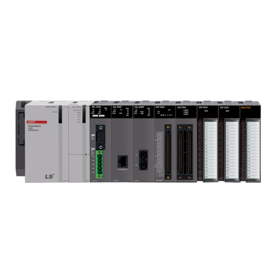
- Page 1 Right choice for ultimate yield LSIS strives to maximize customers' profit in gratitude of choosing us for your partner. Programmable Logic Controller XGI CPU Module XGT Series User’s Manual XGI-CPUU XGI-CPUH XGI-CPUS XGI-CPUE XGI-CPUU/D XGI-CPUUN Read this manual carefully before ...
- Page 2 Safety Instruction Before using the product … For your safety and effective operation, please read the safety instructions thoroughly before using the product. ► Safety Instructions should always be observed in order to prevent accident or risk with the safe and proper use the product. ►...
- Page 3 Safety Instruction Safety Instructions when designing Warning Please, install protection circuit on the exterior of PLC to protect the whole control system from any error in external power or PLC module. Any abnormal output or operation may cause serious problem in safety of the whole system.
- Page 4 Safety Instruction Safety Instructions when designing Caution I/O signal or communication line shall be wired at least 100mm away from a high-voltage cable or power line. If not, it may cause abnormal output or operation. Safety Instructions when designing Caution ...
- Page 5 Safety Instruction Safety Instructions when wiring Warning Prior to wiring, be sure that power of PLC and external power is turned off. If not, electric shock or damage on the product may be caused. Before PLC system is powered on, be sure that all the covers of ...
- Page 6 Safety Instruction Safety Instructions for test-operation or repair Warning Don’t touch the terminal when powered. Electric shock or abnormal operation may occur. Prior to cleaning or tightening the terminal screws, let all the external power off including PLC power. If not, electric shock or abnormal operation may occur.
- Page 7 7. Digital I/O module added Ch7.2.10 XGI-A21C, XGQ-TR1C Ch7.3.11 8. PID bit flag address modified Ch14.5 9. Flag added App1.1 ※ The number of User’s manual is indicated right part of the back cover. ⓒ LS Industrial Systems Co., Ltd 2013 All Rights Reserved.
- Page 8 6. List of Configuration Products updated Ch2.2 V 2.0 ‘16.03 1. Smart Link manual supplemented Ch7.6 ※ The number of User’s manual is indicated right part of the back cover. ⓒ LS Industrial Systems Co., Ltd 2013 All Rights Reserved.
- Page 9 About User’s Manual Congratulations on purchasing PLC of LS Industrial System Co.,Ltd. Before use, make sure to carefully read and understand the User’s Manual about the functions, performances, installation and programming of the product you purchased in order for correct use and importantly, let the end user and maintenance administrator to be provided with the User’s Manual.
-
Page 10: Table Of Contents
TABLE OF CONTENTS ◎ TABLE OF CONTENTS ◎ Chapter 1 Introduction ........................1-1~1-6 1.1 How to use the User’s Manual ......................1-1 1.2 Features ............................1-2 1.3 Terms & Definitions ..........................1-4 Chapter 2 System Configuration....................2-1~2-14 2.1 XGI Series System Configuration ..................... 2-1 2.2 Components List .......................... - Page 11 TABLE OF CONTENTS 5.2.3 Interrupt ............................. 5-8 5.3 Operation Mode..........................5-13 5.3.1 RUN mode ..........................5-13 5.3.2 STOP mode ..........................5-14 5.3.3 DEBUG mode ......................... 5-14 5.3.4 Changing operation mode ...................... 5-15 5.4 Memory ............................5-16 5.4.1 Program memory ........................5-16 5.4.2 Data memory ..........................
- Page 12 TABLE OF CONTENTS 7.2.4 32 point DC24V input module(source/sink type) ..............7-6 7.2.5 32 point DC24V input module(source type) ................7-7 7.2.6 64 point DC24V input module(source/sink type) ..............7-8 7.2.7 64 point DC24V input module(source type) ................7-9 7.2.8 16 point AC110V input module ....................7-10 7.2.9 8 point AC220V input module ....................7-11 7.2.10 8 point AC220V isolated input module ..................
- Page 13 12.1.2 Panel ............................. 12-2 12.1.3 Cable ............................. 12-3 12.2 Requirements Complying with Low Voltage Direction ..............12-4 12.2.1 Specifications applicable to XGT series ................12-4 12.2.2 Selection of XGT series PLC ....................12-4 Chapter 13 Troubleshooting ...................... 13-1~13-13 13.1 Basic Troubleshooting Procedure ....................13-1 13.2 Troubleshooting ..........................
- Page 14 TABLE OF CONTENTS 14.4 PID Instruction ..........................14-6 14.4.1 PID loop state ........................14-6 14.4.2 PID instruction group ......................14-7 14.5 PID Configuration .......................... 14-9 14.5.1 Common bit area ........................ 14-12 14.5.2 Individual data operation ..................... 14-15 14.6 Convenient Functions of PID Instruction ..................14-22 14.6.1 Various control method including PID .................
-
Page 15: How To Use The User's Manual
Chapter 1 Introduction Chapter 1 Introduction 1.1 How to use the User’s Manual The User’s Manual describes the specifications, performances and operations of each product necessary for using the XGT PLC System consisting of XGI series CPU modules. The user’s manual consists of the following chapters Chapter Title Description... -
Page 16: Features
Chapter 1 Introduction 1.2 Features XGI has the following features. 1) Compact size Realizing the innovatively compact size as maintaining the performance, it requires a smaller space. 2) High speed processing (1) XGI-CPUUN • Sequence command : 8.5 ns • MOV command : 25.5 ns •... - Page 17 Chapter 1 Introduction 5) Various communication systems The systems provide various network functions to meet user’s convenience, compatibility and performance. • A network can be established without ladder programming • The exclusive tool(XG-PD) can set a network and monitor operation status. •...
-
Page 18: Terms & Definitions
Chapter 1 Introduction 1.3 Terms & Definitions The paragraph describes the terms used in the user’s manual. Term Definition Remarks i.e.) CPU A standard element with a specific function to structure a system such as I/O module, power Module board assembled to be inserted into the motherboard base module, I/O module and etc i.e.) basic unit,... - Page 19 Chapter 1 Introduction Term Definition Remarks As an abbreviation of Real Time Clock, it is collectively referred as a universal IC with a function of clock A timer to monitor pre-determined execution time of a program and Watchdog Timer generate a warning unless it is not complete within the time Operation unit to immediately output operation results for an input such Function as four arithmetical operations and comparative operations, instead of...
- Page 20 Chapter 1 Introduction Term Definition Remarks Current flows into PLC input terminal from switch when Input Signal is ON Current Sink input Z: input impedance Switch Power − Common Current flows into switch from PLC input terminal when Input Signal is ON Common Source input Z: input impedance...
-
Page 21: Xgi Series System Configuration
Chapter 2 System Configuration Chapter 2 System Configuration XGI series are furnished with types of products to structure a basic system, computer link and network system. This chapter describes how to structure each system and the features. 2.1 XGI Series System Configuration The system configuration of the XGI series is as follows. -
Page 22: Components List
Chapter 2 System Configuration 2.2 Components List XGI Series consist of the following products. Product Model Description Remarks • CPU module(max. I/O points : 6,144, Program capacity.: 2MB) XGI-CPUUN • CPU module(max. I/O points : 6,144, Program capacity.: 1MB) XGI-CPUU/D •... - Page 23 Chapter 2 System Configuration Product Model Description Remarks • for 4 module installation XGB-M04A • for 6 module installation XGB-M06A Main Base • for 8 module installation XGB-M08A • for 12 module installation XGB-M12A • for 4 module installation XGB-E04A •...
- Page 24 Chapter 2 System Configuration Product Model Description Remarks • Voltage Output: 4 channels XGF-DV4A • DC 1 ~ 5V / 0 ~ 5V / 0 ~ 10V / −10 ~ +10V • Current Output:: 4 channels XGF-DC4A • DC 4 ~ 20mA / 0 ~ 20mA •...
- Page 25 Chapter 2 System Configuration Product Model Description Remarks • Pulse output (Open Collector type), 3 axes XGF-PO3A • Pulse output (Open Collector type), 2 axes XGF-PO2A • Pulse output (Open Collector type), 1 axis XGF-PO1A • Pulse output (Line Drive type), 3 axes XGF-PD3A •...
- Page 26 Chapter 2 System Configuration Product Model Description Remarks • Fast Ethernet(optical), Master XGL-EFMF • 100/10 Mbps support • Fast Ethernet(electrical), Master FEnet Module XGL-EFMT • 100/10 Mbps support (Optical/Elec.) • Fast Ethernet Switch module(optical) XGL-ESHF • Fast Ethernet Switch module(electrical) XGL-EH5T •...
- Page 27 Chapter 2 System Configuration Note 1) For the further information about active coupler, optical converter, repeater and block type remote module, which are network devices, refer to the user’s manual of network. 2) O/S version of communication module applicable to XGI system is as follows. Module Name IFOS...
-
Page 28: Basic System
Chapter 2 System Configuration 2.3 Basic System 2.3.1 Configuration of basic system The basic system structured by linking main base and extension base features the follows. XGI-CPUU / CPUH / CPUU/D Item XGI-CPUS XGI-CPUE CPUUN Max. extension stages 7 stages 3 stages 1 stage Max. -
Page 29: Max. Configuration Of The Base System
Chapter 2 System Configuration 2.3.2 Max. configuration of the base system Slot no.: 0.0.0 0.1.0 0.2.0 0.3.0 0.4.0 0.5.0 0.6.0 0.7.0 System Configuration Main base Power example (base no.:0) 0.0.15 0.1.15 0.2.15 0.3.15 0.4.15 0.5.15 0.6.15 0.7.15 - XGI-CPUU - 8 slot base - if 16 point Extension cable Slot no.:... -
Page 30: Connection Of Terminating Resistance
Chapter 2 System Configuration 2.3.3 Connection of terminating resistance If a system requires the main base and extension base to be connected, the terminating resistance should be attached on the extension connector(OUT) of the last extension base in order to improve the reliability. If the only main base is used, the terminating resistance does not need installing. -
Page 31: Module Selection When Configuring Basic System
Chapter 2 System Configuration 2.3.4 Module selection when configuring basic system When configuring basic system, you must consider about size of each module’s Data Refresh area. Data Refresh area is used for data transmission between CPU and modules in XGK/XGI CPU system. Data Refresh area is allocated to CPU memory, irrespective of module’s operation. - Page 32 Chapter 2 System Configuration Item Type Refresh Size Item Type Refresh Size XGF-PO3H XGL-FMEA XGF-PO4H XGL-C22A XGF-PD1H XGL-C42A XGF-PD2H XGL-CH2A APM module XGF-PD3H XGL-EIMT Communication ( Advanced Position XGF-PD4H XGL-EIMH module module ) XGF-PN8A XGL-EIMF XGF-PN8B XGL-ES4T XGF-M16M XGL-BBM XGF-M32E XGL-EIPT 2.3.4.2 Calculation of Data Refresh area’s size 1) Limit of Data Refresh area’s size...
-
Page 33: Network System
Chapter 2 System Configuration 2.4 Network System The XGI series support various network systems to facilitate system structure. It provides Ethernet(FEnet.FDEnet) and Cnet for the communication between PLC and PLC or a higher system and it also provides the dedicated Ethernet(FEEnet), Profibus-DP, DeviceNet, Rnet and others as a lower control network system. 2.4.1 Inter-System network 1) Local Network It is available to install max. -
Page 34: Remote I/O System
Chapter 2 System Configuration 2.4.3 Remote I/O system Smart I/O series is the network system to control the I/O module remotely installed and the network systems are Profibus-DP, DeviceNet, Rnet, Cnet and others. 1) I/O System Application by Network Types Remote I/O modules are classified as follows. - Page 35 Chapter 3 General Specifications Chapter 3 General Specifications 3.1 General Specifications The general specifications of the XGT series are as follows. Items Specifications Related standards Ambient 0 ~ 55 °C temperature Storage −25 ~ +70 °C temperature Ambient 5 ~ 95%RH (Non-condensing)
-
Page 36: Performance Specifications
Chapter 4 CPU Module Chapter 4 CPU Module 4.1 Performance Specifications The performance specifications of the CPU module (XGI-CPU) are as follows. Specifications Item Remarks XGI-CPUUN XGI-CPUU/D XGI-CPUU XGI-CPUH XGI-CPUS XGI-CPUE Operation system Reiterative operation, fixed cycle operation, constant scan I/O Control system Scan synchronous batch processing system(refresh system), direct system by command Program language... - Page 37 Chapter 4 CPU Module Specifications Item Remarks XGI-CPUUN XGI-CPUU/D XGI-CPUU XGI-CPUH XGI-CPUS XGI-CPUE Occupying 20 bytes No point limit of symbolic variable area Timer Time range: 0.001~ 4,294,967.295 second(1,193 hours) per point Occupying 8 bytes No point limit of symbolic variable area Counter ...
- Page 38 Chapter 4 CPU Module Note Supported functions according to CPU OS version: the following OS version and XG500 version is needed for each function CPU OS XG5000 Function Remark V3.0 V3.1 Event input module(XGF-SOEA) V3.1 V3.2 Effective conversion value, aslarm function of analog input module Enhanced password function (in order to connect, XG5000 V3.4 or above is needed.) V3.20...
-
Page 39: Names And Functions Of Parts
Chapter 4 CPU Module 4.2 Names and Functions of Parts -a -b XGI-CPUU -c RUN/STOP -d -e -f Boot -a /Nor REMOTE -b M.XCHG -c STOP RST D.CLR Name Description Shows the operation status of the CPU module. ... - Page 40 Chapter 4 CPU Module Name Description On(red): displaying an error of operation disabled ① - c ERR LED Off: displaying normal operation On(red): ▶ If ‘User Defined Flag’ is ‘On’ ▶ Operation in erroneous status by ‘Operation in Error Status’ setting PS LED ①...
- Page 41 Chapter 4 CPU Module Name Description It replaces a module during operation. M.XCHG On (right): replacing a module ② - c (module change ▶ A module is replaced by operating the key switch switch) Off(left): module is replaced completely Setting the operation mode of the CPU module.
- Page 42 Chapter 4 CPU Module The name of each part about XGI-CPUUN is as followings. -a -b XGI-CPUUN -c RUN/STOP REM. -d ERR. -e P.S. BAT. -f -a REMOTE M.XCHG -b RUN STOP RST D.CLR LINK TX/RX 10/100 BASE-TX Name...
- Page 43 Chapter 4 CPU Module Name Description On(red): displaying an error of operation disabled ① - c ERR LED Off: displaying normal operation On(red): ▶ If ‘User Defined Flag’ is ‘On’ ▶ Operation in erroneous status by ‘Operation in Error Status’ setting PS LED ①...
- Page 44 Chapter 4 CPU Module Name Description You can enable/disable Reset/D.Clear switch in “XG5000 Basic Parameter Basic Operation Setup” 1. When Reset switch is enabled Operation Result move to left return to center Reset move to left keep 3 seconds or Overall reset above ...
-
Page 45: Battery
Chapter 4 CPU Module 4.3 Battery 4.3.1 Battery specifications Item Specifications Nominal Voltage / Current DC 3.0 V / 1,800 mAh Warranty period 5 years(at ambient temperature) Applications Program/data backup, RTC operation in case of power failure Type LiMnO2 Lithium Battery φ... -
Page 46: Replacement
Chapter 4 CPU Module 4.3.4 Replacement A battery used as a backup power for program and data in case of power failure needs replacing regularly. The program and data is kept by the super capacity for about 30 minutes even after removing the battery, but it needs urgently replacing it as soon as possible. Replace a battery in accordance with the following steps. -
Page 47: Program Introduction
Chapter 5 Program Structure and Operation Method Chapter 5 Program Structure and Operation Method 5.1 Program Introduction 5.1.1 Program operation methods 1) Cyclic operation (Scan) It executes a program created by the basic program operation method of the PLC from the first to the last step cyclically and the procedure is called ‘Program Scan.’... - Page 48 Chapter 5 Program Structure and Operation Modes 2) Interrupt operation (fixed cycle, internal device operation) It temporarily stops a currently executing program operation and immediately processes an operation corresponding to the interrupt program in case an urgent event occurs during the operation of PLC program. The signal notifying the CPU module about the emergency is called ‘Interrupt signal’...
- Page 49 Chapter 5 Program Structure and Operation Method 5.1.3 Scan time The time required to complete it from the first step 0 to the next step 0 of a program, that is, a time taken for a control operation is called ‘scan time.’...
-
Page 50: Scan Time
Chapter 5 Program Structure and Operation Modes (2) Example The scan time of a system consisting of CPU(program 16kstep) + 32 points, 6 I/O modules + 6 analogue modules + 4 communication modules(200 bytes 8 blocks per module) is as follows. Scan time(㎲) = ladder execution time + system processing time + digital module I/O processing time + analogue I/O processing time + communication module processing time + XG5000 Service processing time = (16000 x 0.028) + (600) + (20 x 6) + (75 x 6) + (185 x 8 x 4) + (100) -
Page 51: Program Execution
Chapter 5 Program Structure and Operation Method 5.2 Program Execution 5.2.1 Program configuration Program consists of every functional element necessary for executing a specific control and is saved into the internal RAM of the CPU module or a flash memory. The functional elements can be categorized as follows. - Page 52 Chapter 5 Program Structure and Operation Modes 1) Scan program (1) Functions • It cyclically executes an operation from the first step 0 to the last step according to the sequences that the program is created in order to process a signal that repeats uniformly per scan. •...
- Page 53 Chapter 5 Program Structure and Operation Method 5.2.3 Interrupt To help your understanding about interrupt function, it describes how to set XG5000 program, a kind of XGT programming software briefly(for further information about the XG5000, please refer to the user’s manual of XG5000). Scan Program Interrupt 1 Interrupt 1 occurs...
-
Page 54: Interrupt
Chapter 5 Program Structure and Operation Modes 1) Creating an interrupt program Create a task in the project window of XG5000 as follows and add programs to be executed by each task. For further information, please refer to the user’s manual of XG5000. 2) Task Types The below table summarizes the types and functions of tasks. - Page 55 Chapter 5 Program Structure and Operation Method (2) Execution priority If several tasks to execute are waiting, it processes from the highest priority task program. If there are several tasks of same priority, they are processed by the order which is occurred. ...
- Page 56 Chapter 5 Program Structure and Operation Modes (3) Cautions for using a fixed cycle task program If a same task program is to be executed when a fixed cycle task program is in operation or waiting for execution, a new task is ignored. ...
- Page 57 Chapter 5 Program Structure and Operation Method 7) Verification of task program After creating a task program, verify it in accordance with the followings. (1) Is the task set properly? If a task occurs excessively or several tasks occur simultaneously in a scan, it may cause longer scan time or irregularity If a task setting can not be changed, check the max.
- Page 58 Chapter 5 Program Structure and Operation Modes Scan start 1’st scan end 1’st Scan (1’st operation start) (2’nd scan start) program end P0 Execution P1 Execution T_SLOW Detection P2 Execution PROC_1 Detection Time : : Execution without program interruption : Instant stopping during program execution : Delay of program execution ...
-
Page 59: Operation Mode
Chapter 5 Program Structure and Operation Method 5.3 Operation Mode There are three operation modes of the CPU module; RUN mode, STOP mode and DEBUG mode. It describes the operation process at each operation mode. 5.3.1 RUN mode It executes a program operation normally. Start the first scan at RUN mode Initialize data area Determine whether to process by... -
Page 60: Stop Mode
Chapter 5 Program Structure and Operation Modes 5.3.2 STOP mode It stops with no program operation. Program can be transmitted through XG5000 only at remote STOP mode. 1) Processing when a mode is changed Remove the output image area and execute refresh. Therefore, every output data are changed to off state. 2) Operation process (1) Execute I/O refresh. -
Page 61: Changing Operation Mode
Chapter 5 Program Structure and Operation Method 5.3.4 Changing operation mode 1) How to change an operation mode An operation mode can be changed as follows. (1) Mode change by the mode key of the CPU module (2) Change by accessing the programming tool(XG5000) to a communication port of CPU (3) Change of a different CPU module networked by XG5000 accessed to a communication port of CPU (4) Change by using XG5000, HMI and computer link module, which are networked. -
Page 62: Memory
Chapter 5 Program Structure and Operation Modes 5.4 Memory The CPU module contains two types of memory that can be used by a user. One is the program memory to save a user program created to construct a system and the other one is the data memory to provide a device area to save the data during operation. 5.4.1 Program memory The storage capacity and data area type of the program memory are as follows. -
Page 63: Data Memory
Chapter 5 Program Structure and Operation Method 5.4.2 Data memory The storage capacity and data area type of the data memory are as follows. Capacity Item(area) XGI-CPUUN XGI-CPUU/D XGI-CPUU XGI-CPUH XGI-CPUS XGI-CPUE 4M byte Whole data memory area 3M byte 2M byte 1M byte 512K byte... - Page 64 Chapter 5 Program Structure and Operation Modes 1) Data initialization by restart mode There are 3 restart mode related parameters; default, initialization and retain parameter and the initialization methods of each parameter are as follows in the restart mode. (Restart mode sets the parameters when it starts in a run mode.) Mode Cold Warm...
- Page 65 Chapter 5 Program Structure and Operation Method - RUN Mode operation Restart Item Retain M area retain R area Mode Cold Initializing as ‘0’ Initializing as ‘0’ Maintaining the previous value Reset Warm Maintaining the previous value Maintaining the previous value Maintaining the previous value Over all reset Cold / Warm...
- Page 66 Chapter 6 Functions of CPU Module Chapter 6 Functions of CPU Module 6.1 Self-diagnostic Function (1) The self-diagnostic is the function that the CPU module diagnoses any trouble of the PLC system. (2) It detects any trouble when turning on the PLC system or any trouble is found during the operation, avoid the system from malfunctioning and taking preventive measures.
-
Page 67: Battery Level Check
Chapter 6 Functions of CPU Module 6.1.2 I/O Module check The function checks the I/O module when it starts and during operation as follows. 1) If a module that is not set in the parameter when it starts is installed or is fault; or 2) In case of the detachment of the I/O module or being in trouble during operation, It detects an error. - Page 68 Chapter 6 Functions of CPU Module (3) Operation error while a user program is operating In case of numerical operation error as a trouble occurring while a user program is operating, error flag(_ERR) and error latch flag(_LER) are displayed and the system resumes operation. If an operation time exceeds the overtime delay limit or the built-in I/O module is not controlled, the system stops.
-
Page 69: Clock Function
Chapter 6 Functions of CPU Module 6.2 Clock Function The CPU module contains a clock element(RTC), which operates by the backup battery even in case of power-off or instantaneous interruption. By using the clock data of RTC, the time control for the operation or trouble logs of the system is available. The present time of RTC is updated to the clock-related F device per scan. - Page 70 Chapter 6 Functions of CPU Module 3) Clock data modified by program A user also can set the value of clock by using a program. It is used when setting the time manually by external digital switches or creating a system to calibrate a clock periodically on network. In the ‘RTC-SET’...
-
Page 71: Remote Functions
Chapter 6 Functions of CPU Module 6.3 Remote Functions The CPU module can change operation by communication, besides the key switch installed on it. To operate it remotely, it is necessary to set ‘REM’ switch(no. 2 dip switch of 4 pin dip switch) of the CPU module ‘ON’ and move ‘RUN/STOP’ switch to ‘STOP’ position. 1) Types of remote operation (1) Operation by connecting to XG5000 via USB or RS-232C port installed on the CPU module (2) Other PLC networked on the PLC can be controlled with the CPU module connected to XG5000. - Page 72 Chapter 6 Functions of CPU Module 5) Flash memory operation mode (1) What is the flash operation mode? It means that the system operates by the backup program in flash in case the data in program ram are damaged. If selecting “Flash Memory Operation Mode”, it starts operation after being moved to the program memory of the CPU module when the operation mode is changed from other mode to RUN mode or when restarting.
- Page 73 Chapter 6 Functions of CPU Module Note 1) The default is ‘Flash Memory Operation Mode deselected’. 2) Flash memory operation mode is maintained as ‘On’ as long as it is not ‘Off’ by XG5000. 3) Flash memory operation mode can be changed, irrespective of RUN/STOP mode. 4) Flash memory operation mode can be set by the online menu of XG5000 when executing flash ‘operation mode setting’...
-
Page 74: Forcible On/Off Of I/O
Chapter 6 Functions of CPU Module 6.4 Forcible On/Off of I/O The forcible I/O function is used to forcibly turn on or off I/O area, irrespective of program execution results. 6.4.1 Forcible I/O Setting Click ‘Forcible I/O Setting’ in online mode. To set forcible I/O, select the flag of a contact to set and the data checkbox To set “1”, select the flag and data of a bit and then, select a flag. -
Page 75: Direct I/O Operation
Chapter 6 Functions of CPU Module 6.4.2 Forcible On / Off processing time and processing method (1) Forcible input ‘Input’ replaces the data of a contact set by Forcible On/Off from the data read from input module at the time of input refresh with the forcibly set data and updates input image area. -
Page 76: Saving Operation Logs
Chapter 6 Functions of CPU Module 6.6 Saving Operation Logs There are four types of operation logs; Error log, Mode change log, Shut down log and System log. It saves the time, frequency and operation of each event into memory and a user can conveniently monitor them through XG5000. Operation log is saved within the PLC unless it is deleted by XG5000. -
Page 77: Diagnosing Faults Of External Device
Chapter 6 Functions of CPU Module 6.7 Diagnosing Faults of External Device It is the flag that a user detects a fault of external device so that the suspension/warning of a system could be easily realized. If using the flag, it can display a fault of external device, instead of creating a complex program and monitor a fault position without XG5000 and source program. -
Page 78: Fault Mask Function
Chapter 6 Functions of CPU Module 6.8 Fault Mask Function 6.8.1 Applications and operations • Fault mask helps a program keep operating even though a module is in trouble during operation. A module designated as fault mask normally works until a fault occurs. •... -
Page 79: I/O Module Skip Function
Chapter 6 Functions of CPU Module 6.9 I/O Module Skip Function 6.9.1 Applications and operations During operation, the I/O module skip function excludes a designated module from the operation. For the designated module, the data update and fault diagnostics of I/O data stops as soon as being designated. It is available when temporarily operating it with the fault excluded. -
Page 80: Module Replacement During Operation
Chapter 6 Functions of CPU Module 6.10 Module Replacement during Operation A module can be replaced during operation in the XGT system. However, a special attention should be paid because the module replacement during operation may cause malfunction. Make sure to follow the steps directed in the user’s manual. 6.10.1 Cautions for usage •... -
Page 81: Allocating I/O Number
Chapter 6 Functions of CPU Module 6.11 Allocating I/O Number I/O number allocation is to assign the address to the I/O terminal of each module to read data from an input module and output it to an output module. The I/O number allocation is related with base number, slot position and module type. The number is allocated by the fixed method in the XGI-CPUU. - Page 82 Chapter 6 Functions of CPU Module If user selects Local Ethernet Parameter item, Local Ethernet Parameter setting window will be displayed. To use the Local Ethernet function, user should set the parameters. (1) TCP/IP Setting Classification Description IP address Specify the IP Address of the applicable CPU module. Subnet mask Value necessary to check if destination station is on the same network of the applicable station.
- Page 83 Chapter 6 Functions of CPU Module (2) Driver(Server) setting Classification Description XGT server Set when operated as dedicated communication server (slave) Modbus TCP/IP server Set when operated as Modbus server driver (slave) (3) Host table setting Classification Description Access allowed to applicable module of IP address registered in host table Enable host table (unregistered client(IP address) is prohibited from connection when enabled) 6.13.2 Local Ethernet connection with XG5000...
- Page 84 Chapter 6 Functions of CPU Module 6.13.3 Local Ethernet connection with XGT Server. Set the Local Ethernet Parameters as shown below figure. User can use it as a XGT Server (LSIS dedicated Protocol Communication). 6.13.4 Local Ethernet connection with TCP/IP Server. Set the Local Ethernet Parameters as shown below figure.
- Page 85 Chapter 6 Functions of CPU Module Note 1) Modbus TCP/IP server connection function allows RST packet transmission depending on the network condition.(TCP/IP protocol) So the user devices connecting to CPU module should have RST packet process. 2) Connection to user devices can be disconnected for retransmission time-out. Retransmission time-out = retransmission time-out value(set in the Local Ethernet Parameter window) x 30ms 3) Too much Network loads can affect a scan time.
-
Page 86: Cautions For Selecting Modules
Chapter 7 I/O Module Chapter 7 I/O Module 7.1 Cautions for Selecting Module It describes the cautions when selecting digital I/O modules used for the XGI series. 1) There are two digital input types; current sink input and current source input Since the wiring method of external input power varies in a DC input module, it should be selected considering the specifications of input connectors. - Page 87 Chapter 7 I/O Module 7) The following figure shows the relay life of relay output module. It also shows the max. life of relay used for relay output. AC 125V resistance load DC 30V resistance load AC 250V resistance load Current(A) 8) A clamped terminal with sleeve can not be used for the XGI terminal strip.
-
Page 88: Digital Input Module Specifications
Chapter 7 I/O Module 7.2 Digital Input Module Specifications 7.2.1 8 point DC24V input module (source/sink type) Module type DC Input module Spec. XGI-D21A Input point 8 points Insulation method Photo coupler insulation Rated input voltage DC24V Approx. 4 ㎃ Rated input current Voltage range DC20.4~28.8V (5% and lower ripple rate ) -
Page 89: Point Dc24V Input Module(Source/Sink Type)
Chapter 7 I/O Module 7.2.2 16 point DC24V input module (source/sink type) Module type DC Input module Spec. XGI-D22A Input point 16 points Insulation method Photo coupler insulation Rated input voltage DC24V Approx. 4 ㎃ Rated input current Voltage range DC20.4~28.8V (5% and lower ripple rate ) Input derating None... -
Page 90: Point Dc24V Input Module(Source Type)
Chapter 7 I/O Module 7.2.3 16 point DC24V input module (source type) Module type DC Input module Spec. XGI-D22B Input point 16 points Insulation method Photo coupler insulation Rated input voltage DC24V Approx. 4 ㎃ Rated input current Voltage range DC20.4~28.8V (5% and lower ripple rate ) Input derating None... -
Page 91: Point Dc24V Input Module(Source/Sink Type)
Chapter 7 I/O Module 7.2.4 32 point DC24V input module (source/sink type) Module type DC Input module Spec. XGI-D24A Input point 32 points Insulation method Photo coupler insulation Rated input voltage DC24V Approx. 4 ㎃ Rated input current Voltage range DC20.4~28.8V (5% and lower ripple rate ) Input derating Refer to the below derating level... -
Page 92: Point Dc24V Input Module(Source Type)
Chapter 7 I/O Module 7.2.5 32 point DC24V input module (source type) Module type DC Input module Spec. XGI-D24B Input point 32 points Insulation method Photo coupler insulation Rated input voltage DC24V Approx. 4 ㎃ Rated input current Voltage range DC20.4~28.8V (5% and lower ripple rate ) Input derating Refer to the below derating level... -
Page 93: Point Dc24V Input Module(Source/Sink Type)
Chapter 7 I/O Module 7.2.6 64 point DC24V input module (source/sink type) Module type DC Input module Spec. XGI-D28A Input point 64 points Insulation method Photo coupler insulation Rated input voltage DC24V Approx. 4 ㎃ Rated input current Voltage range DC20.4~28.8V (5% and lower ripple rate ) Input derating Refer to the below derating level... -
Page 94: Point Dc24V Input Module(Source Type)
Chapter 7 I/O Module 7.2.7 64 point DC24V input module (source type) Module type DC Input module Spec. XGI-D28B Input point 64 points Insulation method Photo coupler insulation Rated input voltage DC24V Approx. 4 ㎃ Rated input current Voltage range DC20.4~28.8V (5% and lower ripple rate ) Input derating Refer to the below derating level... -
Page 95: Point Ac110V Input Module
Chapter 7 I/O Module 7.2.8 16 point AC110V input module Module type AC Input module Spec. XGI-A12A Input point 16 points Insulation method Photo coupler insulation AC100-120V(+10/-15%) 50/60 ㎐(±3 ㎐) (5% and lower distortion) Rated input voltage Approx. 8 ㎃ (AC100,60 ㎐) , approx. 7 ㎃ (AC100,50 ㎐) Rated input current Max. -
Page 96: Point Ac220V Input Module
Chapter 7 I/O Module 7.2.9 8 point AC220V input module Module type AC input module Spec. XGI-A21A Input point 8 points Insulation method Photo coupler insulation AC100-240V(+10/-15%) 50/60 ㎐(±3 ㎐) (5% and lower distortion) Rated input voltage Approx. 17 ㎃ (AC200,60 ㎐) , approx. 14 ㎃ (AC200,50 ㎐) Rated input current Max. -
Page 97: Point Ac220V Isolated Input Module
Chapter 7 I/O Module 7.2.10 8 point AC220V isolated input module Module type AC input module Spec. XGI-A21C Input point 8 points Insulation method Photo coupler insulation AC100-240V(+10/-15%) 50/60 ㎐(±3 ㎐) (5% and lower distortion) Rated input voltage Approx. 17 ㎃ (AC200,60 ㎐) , approx. 14 ㎃ (AC200,50 ㎐) Rated input current Max. -
Page 98: Point Relay Output Module
Chapter 7 I/O Module 7.3 Digital Output Module Spec. 7.3.1 8 point relay output module Module type Relay output module Spec. XGQ-RY1A Output point 8 points Insulation method Relay insulation Rated load voltage/current DC24V 2A(resistance load) / AC220V 2A(COSΨ = 1) Min. -
Page 99: Point Relay Output Module
Chapter 7 I/O Module 7.3.2 16 point relay output module Module type Relay output module Spec. XGQ-RY2A Output point 16 points Insulation method Relay insulation Rated load voltage/current DC24V 2A(resistance load) / AC220V 2A(COSΨ = 1) Min. load voltage / current DC5V / 1mA Max. -
Page 100: Point Relay Output Module(Surge Killer Built-In Type)
Chapter 7 I/O Module 7.3.3 16 point relay output module (Surge Killer built-in type) Module Relay output module type XGQ-RY2B Spec. Output point 16 points Insulation method Relay insulation Rated load voltage/current DC24V 2A(resistance load) / AC220V 2A(COSΨ = 1) Min. -
Page 101: Point Triac Output Module
Chapter 7 I/O Module 7.3.4 16 point Triac output module Module type Triac output module Spec. XGQ-SS2A Output point 16 points Insulation method Photo coupler insulation Rated load voltage AC 100-240V (50 / 60 Hz) Max. load voltage AC 264V Max. -
Page 102: Point Transistor Output Module(Sink Type)
Chapter 7 I/O Module 7.3.5 16 point transistor output module (sink type) Module type Transistor output module Spec. XGQ-TR2A Output point 16 points Insulation method Photo coupler insulation Rated load voltage DC 12 / 24V Operating load voltage range DC 10.2 ~ 26.4V Max. -
Page 103: Point Transistor Output Module(Sink Type)
Chapter 7 I/O Module 7.3.6 32 point transistor output module(sink type) Module type Transistor output module Spec. XGQ-TR4A Output point 32 point Insulation method Photo coupler insulation Rated load voltage DC 12 / 24V Operating load voltage range DC 10.2 ~ 26.4V Max. -
Page 104: Point Transistor Output Module(Sink Type)
Chapter 7 I/O Module 7.3.7 64 point transistor output module (sink type) Module type Transistor output module Spec. XGQ-TR8A Output point 64 points Insulation system Photo coupler insulation Rated load voltage DC 12 / 24V Operating load voltage range DC 10.2 ~ 26.4V Max. -
Page 105: Point Transistor Output Module(Source Type)
Chapter 7 I/O Module 7.3.8 16 point transistor output module (source type) Module type Transistor output module Spec. XGQ-TR2B Output point 16 points Insulation method Photo coupler insulation Rated load voltage DC 12 / 24V Operating load voltage range DC 10.2 ~ 26.4V Max. -
Page 106: Point Transistor Output Module(Source Type)
Chapter 7 I/O Module 7.3.9 32 point transistor output module (source type) Module type Transistor output module Spec. XGQ-TR4B Output point 32 points Insulation method Photo coupler insulation Rated load voltage DC 12 / 24V Operating load voltage range DC 10.2 ~ 26.4V Max. -
Page 107: Point Transistor Output Module(Source Type)
Chapter 7 I/O Module 7.3.10 64 point transistor output module (source type) Module type Transistor output module Spec. XGQ-TR8B Output point 64 points Insulation method Photo coupler insulation Rated load voltage DC 12 / 24V Operating load voltage range DC 10.2 ~ 26.4V Max. -
Page 108: Point Transistor Isolated Output Module
Chapter 7 I/O Module 7.3.11 8 point transistor isolated output module Module type Transistor output module Spec. XGQ-TR1C Output point 8 points Insulation method Photo coupler insulation Rated load voltage DC 12 / 24V Operating load voltage range DC 10.2 ~ 26.4V Max. -
Page 109: Point(Dc Input Transistor Output) I/O Combined Module
Chapter 7 I/O Module 7.4 Digital I/O Module Specifications 7.4.1 32 point (DC input · transistor output) I/O combined module XGH-DT4A Input Output Input point 16 points Output point 16 points Insulation method Photo coupler insulation Insulation method Photo coupler insulation Rated input voltage DC 24V Rated load voltage... -
Page 110: Event Input Module
Chapter 7 I/O Module 7.5 Event Input Module 7.5.1 Event Input Module (Source/Sink type) Specification XGF-SOEA Input point 32 point Insulation method Photo coupler insulation Memory size Records 1Mbit event information (300 event information per XGF-SOEA module) Precision 1 ms (±2ms : error between modules) Rated input voltage DC24V Rated input current... -
Page 111: Modules Accessible To Smart Link
7.6.1 Modules accessible to Smart Link From digital I/O modules used for XGT Series, the modules accessible to Smart Link are as follows. 32 point modules need a Connector(40 Pin x 1), 64 point modules need 2 connectors(40 Pin x 2) -
Page 112: Smart Link Mapping Table
Chapter 7 I/O Module 7.6.3 Smart Link Mapping Table ❶ ❷ : Module using 1ea Cable : Module using 2ea Cable 7.6.4 Smart Link Connection Cable Smart Link 7-27... -
Page 113: Smart Link Connection Diagram
Chapter 7 I/O Module 7.6.5 Smart Link Connection Diagram (1) XGI-D24A/B 1) Applicable Smart Link Model Cable Length of Cable C40HF-05PB-1B 0.5m C40HF-10PB-1B TG7-1H40S C40HF-15PB-1B 1.5m C40HF-20PB-1B C40HF-30PB-1B Terminal board 0.5m C40HF-05PB-1B C40HF-10PB-1B TG7-1H40CA C40HF-15PB-1B 1.5m (Common120Pin1Added) C40HF-20PB-1B C40HF-30PB-1B 2) Connection Diagram (XGI-D24A/B) (a) TG7-1H40S 7-28... - Page 114 Chapter 7 I/O Module (b) TG7-1H40CA Common Contacts set1 Common Contacts set2 7-29...
- Page 115 Chapter 7 I/O Module (2) XGI-D28A/B 1) Applicable Smart Link Model Cable Length of Cable C40HF-05PB-1B 0.5m C40HF-10PB-1B TG7-1H40S C40HF-15PB-1B 1.5m C40HF-20PB-1B C40HF-30PB-1B Terminal board C40HF-05PB-1B 0.5m C40HF-10PB-1B TG7-1H40CA C40HF-15PB-1B 1.5m (Common120Pin1Added) C40HF-20PB-1B C40HF-30PB-1B 2) Connection Diagram (XGI-D28A/B) (a) TG7-1H40S 7-30...
- Page 116 Chapter 7 I/O Module (b) TG7-1H40CA Common Contacts set1 Common Contacts set2 7-31...
- Page 117 Chapter 7 I/O Module (3) XGQ-TR4A/8A 1) Applicable Smart Link Model Cable Length of Cable C40HF-05PB-1B 0.5m C40HF-10PB-1B TG7-1H40S C40HF-15PB-1B 1.5m C40HF-20PB-1B C40HF-30PB-1B Terminal board C40HF-05PB-1B 0.5m C40HF-10PB-1B TG7-1H40CA C40HF-15PB-1B 1.5m (Common120Pin1Added ) C40HF-20PB-1B C40HF-30PB-1B C40HF-05PB-1 0.5m C40HF-10PB-1 Relay R32C-NS5A-40P C40HF-15PB-1 1.5m board...
- Page 118 Chapter 7 I/O Module (b) TG7-1H40CA Common Contacts set1 Common Contacts set2 (c) R32C-NS5A-40P 7-33...
- Page 119 Chapter 7 I/O Module (4) XGQ-TR4B/8B 1) Applicable Smart Link Model Cable Length of Cable C40HF-05PB-1B 0.5m C40HF-10PB-1B TG7-1H40S C40HF-15PB-1B 1.5m C40HF-20PB-1B C40HF-30PB-1B Terminal board C40HF-05PB-1B 0.5m C40HF-10PB-1B TG7-1H40CA C40HF-15PB-1B 1.5m (Common120Pin1Added ) C40HF-20PB-1B C40HF-30PB-1B C40HF-05PB-XGP1 0.5m C40HF-10PB-XGP1 Relay R32C-PS5A-40P C40HF-20PB-XGP1 board (Source type)
- Page 120 Chapter 7 I/O Module (b) TG7-1H40CA Common Contacts set1 Common Contacts set2 (c) R32C-PS5A-40P 7-35...
- Page 121 Chapter 7 I/O Module (5) XGF-SOEA 1) Applicable Smart Link Model Cable Length of Cable C40HF-05PB-1B 0.5m C40HF-10PB-1B TG7-1H40S C40HF-15PB-1B 1.5m C40HF-20PB-1B C40HF-30PB-1B Terminal board 0.5m C40HF-05PB-1B C40HF-10PB-1B TG7-1H40CA C40HF-15PB-1B 1.5m (Common120Pin1Added ) C40HF-20PB-1B C40HF-30PB-1B 2) Connection Diagram (XGF-SOEA) (a) TG7-1H40S 7-36...
- Page 122 Chapter 7 I/O Module (b) TG7-1H40CA Common Contacts set1 Common Contacts set2 7-37...
-
Page 123: Smart Link Specifications & Dimensions
Chapter 7 I/O Module 7.6.6 Smart Link Specifications & Dimensions (1) TG7-1H40S 1) Specifications Rated Voltage AC, DC 125V Rated Current Withstanding Voltage 600V 1min 100MΩ (DC 500V) Insulation resistance 1.25 ㎟ /MAX Applicable Wire T/B Screw M3 X 10L Screw Torque 1.2N •... - Page 124 Chapter 7 I/O Module (2) TG7-1H40CA 1) Specifications Rated Voltage 125V AC / 24V DC Rated Current Common 10A (Total) 100MΩ (DC 500V) Insulation resistance Withstanding Voltage AC500V 1min AWG22-16 (MAX / 1.5 ㎟) Applicable Wire Contact Screw M3 X 10L Screw Torque 1.2N •...
- Page 125 Chapter 7 I/O Module (3) R32C-N(P)S5A-40P 1) Specifications (a) Relay Board Case Modified PPO Protective Cover Polycarbonate Epoxy 1.6t / 2oz AWG22-16 (MAX / 1.5 ㎟) Applicable Wire T/B Screw M3 X 8L Screw Torque 1.2N • m(12Kgf • cm) -10℃...
-
Page 126: Selection
Chapter 8 Power Module Chapter 8 Power Module This chapter describes the selection, type and specifications of power module. 8.1 Selection The selection of power module is determined by the current that input power voltage and power module should supply to the system, that is, the sum of current consumption of digital I/O module, special module and communication module that are installed on a same base with the power module. - Page 127 Chapter 8 Power Module Commu- Commu- Output Input Special Power AC power nication nication 100V~240V Constant DC5V voltage transformer DC24V load AC power DC power 100V~240V : current consumption of each module DC5V circuit (internal current consumption) : average current consumption of DC24V for output module...
-
Page 128: Specifications
Chapter 8 Power Module 8.2 Specifications Item XGP-ACF1 XGP-ACF2 XGP-AC23 XGP-DC42 Rated input voltage AC110/220V AC220V DC24V Input voltage range AC85V ~ AC264V AC170V ~ AC264V Input frequency 50 / 60 Hz (47 ~ 63 Hz) Inrush current and lower and lower Peak Peak... -
Page 129: Parts' Names
Chapter 8 Power Module 8.3 Parts’ Names It describes the names and applications of parts of the power module. ① ② ③ ④ ⑤ ⑥ ⑦ Name Application Power LED LED to display DC5V power Supplying power to a module requiring DC24V DC24V, 24G terminal ▶... -
Page 130: Examples Of Current Consumption/Power Calculations
Chapter 8 Power Module 8.4 Example of Current Consumption/Power Calculations It describes which power module should be used for the XGT system with the following module. Voltage Type Model CPU module XGI-CPUU 0.96A 12 Slot basic base XGB-M12A Input module XGI-D24A 0.2A Output module... -
Page 131: Specifications
Chapter 9 Base and Extension Cable Chapter 9 Base and Extension Cable 9.1 Specifications 9.1.1 Main base The Main base contains Power module, CPU module, I/O module, Special module and Communication module. Model XGB-M12A XGB-M08A XGB-M06A XGB-M04A Item No. of I/O modules installed Dimensions (mm) 426 X 98 X 19 318 X 98 X 19... -
Page 132: Extension Base
Chapter 9 Base and Extension Cable 9.2 Parts’ Names 9.2.1 Main base Guide hole to attach to the Power module Module attachment base connector connector Hole to attach the base on the Connector to attach a Connector to attach a I/O panel power module module... -
Page 133: Installation
Chapter 10 Installation and Wiring Chapter 10 Installation and Wiring 10.1 Installation 10.1.1 Installation environment The system keeps a high reliability, irrespective of the installation environment. However, to guarantee the reliability and stability, make sure to keep the following cautions. 1) Environmental conditions (1) Install in a control panel resisting to moisture and vibration. - Page 134 Chapter 10 Installation and Wiring The following shows the calculation of PLC system’s power consumption requiring heat protective design. 4) Power Consumption block diagram of the PLC system Commu- Commu- Output Input Special Power AC Power nication nication 100V~240V DC5V Constant Voltage Transformer...
-
Page 135: Cautions For Handling
Chapter 10 Installation and Wiring The calculation of temperature rise within the control panel is displayed as follows. T = W / UA [°C] W : power consumption of the entire PLC system (the above calculated value) A : surface area of control panel [m U : if equalizing the temperature of the control panel by using a fan and others - - - 6 If the air inside the panel is not ventilated - - - - - - - - - - 4 10.1.2 Cautions for handling... - Page 136 Chapter 10 Installation and Wiring Inductive load Output module Surge killer Inductive load Output module Diode (6) Terminal strip Please check the tightness of terminal strip and prevent any wiring impurities(remainder) from being inserted into the PLC when processing terminal strip wiring or screw hole making. It may cause malfunction or trouble. (7) Besides the above, it is prohibited to apply excessive impact on I/O module or separating PCB board from the case.
- Page 137 Chapter 10 Installation and Wiring (6) Please do not install it to the direction as presented below. 10-5...
- Page 138 Chapter 10 Installation and Wiring (7) To avoid any influence of radiating noise or heat, please install the PLC and other devices(relay, electronic contact) with a spacing secured as presented below. 100mm more than 100mm more than 50mm more than 50mm more than 10-6...
-
Page 139: Attachment/Detachment Of Modules
Chapter 10 Installation and Wiring 10.1.3 Attachment/Detachment of modules It describes how to attach or detach a module on the base. 1) Attachment • Please insert the fixation projection on the bottom of a module to the hole of module installation of the base. •... - Page 140 Chapter 10 Installation and Wiring 2) Detachment • Please unscrew the fixation screw on the top of a module. • Please press the hook for module installation with a module held by both hands. • Please pull the bottom of a module toward the top while pressing the hook. •...
- Page 141 Chapter 10 Installation and Wiring 10.2 Wiring It describes the important information about wiring when using the system. 10.2.1 Power wiring 1) Connect a constant voltage transformer when the power variance is larger than the specified range. Power AC power 100V~240V AC power Constant...
-
Page 142: Wiring
Chapter 10 Installation and Wiring 5) AC110V/AC220V/DC24V cables should be compactly twisted and connected in the shortest distance. 6) AC110V/AC220V cable should be as thick as possible(2mm ) to reduce voltage drop. AC110V/ DC24V cables should not be installed close to main circuit cable(high voltage/high current) and I/O signal cable. They should be 100mm away from such cables. -
Page 143: Grounding Wiring
Chapter 10 Installation and Wiring 5) When applying pipe-wiring, make sure to firmly ground the piping. 6) The output line of DC24V should be isolated from AC110V cable or AC220V cable. For a long distance wiring over 200m, please refer to 12.4 Cases in Chapter 12 because it is expected that accident may occur due to leakage current due to inter-cable capacity. -
Page 144: Specifications Of Wiring Cable
Chapter 10 Installation and Wiring 10.2.4 Specifications of wiring cable The specifications of cable used for wiring are as follows. Cable specification (mm Types of external connection Lower limit Upper limit Digital input 0.18 (AWG24) 1.5 (AWG16) Digital output 0.18 (AWG24) 2.0 (AWG14) Analogue I/O 0.18 (AWG24) -
Page 145: Repairs And Maintenance
Chapter 11 Maintenance Chapter 11 Maintenance To maintain PLC in the best condition, please execute the following routine and periodic inspections. 11.1 Repairs and Maintenance The I/O module mainly consists of semiconductor elements, so its life is almost semi permanent. However, such elements may be affected by the environment, so they should be periodically inspected and maintained. -
Page 146: Periodic Inspection
Chapter 11 Maintenance 11.3 Periodic Inspection Please take a measure by checking the following items once or twice every 6 months. Checklist Check method Judgment basis Actions 0 ~ 55 °C Temperature Measure by Adjusting according to the Environment Humidity thermometer/hygrometer 5 ~ 95%RH general spec.(the environment... -
Page 147: Requirements Complying With Emc Specifications
Chapter 12 Compliance with EMC Specifications Chapter 12 Compliance with EMC Specifications 12.1 Requirements Complying with EMC Specifications EMC Directions describe “Do not emit strong electromagnetic wave to the outside: Emission” and “Do not have an influence of electromagnetic wave from the outside: Immunity”, and the applicable products are requested to meet the directions. The chapter summarizes how to structure a system using XGT PLC to comply with the EMC directions. -
Page 148: Panel
Chapter 12 Compliance with EMC Spec. 12.1.2 Panel The PLC is a kind of open device(installed on another device) and it should be installed in a panel. It is because the installation may prevent a person from suffering from an accident due to electric shock as the person contacts with the product(XGT PLC) and the panel can attenuates the noise generating from the PLC. -
Page 149: Cable
1330 2) Fixing a cable in the panel If the extension cable of XGT series is to be installed on the metallic panel, the cable should be 1cm and more away from the panel, preventing the direct contact. The metallic plate of panel may shield noise from electromagnetic wave while it a cable as a noise source is close to the place, it can serve as an antenna. -
Page 150: Requirements Complying With Low Voltage Direction
The low voltage direction requires a device that operates with AC50~1000V, DC 75 ~ 1500V to have proper safety. The followings summarize the cautions for installing and wiring PLC of the XGT series to comply with the low voltage directions. The description is the data based on the applicable requirements and specifications as far as we know but it does not mean that every system manufactured according to the description meets the following specifications. -
Page 151: Basic Troubleshooting Procedure
Chapter 13 Troubleshooting Chapter 13 Troubleshooting The chapter describes types of potential errors that occur while operating the system, causes of errors, how to detect them and corrective measures. 13.1 Basic Troubleshooting Procedure To improve the reliability of a system, it is important to take a corrective measure promptly if a trouble occurs as well as to use highly reliable devices. -
Page 152: Action When Power Led Is Off
Chapter 13 Troubleshooting 13.2.1 Action when POWER LED is off The paragraph describes the orders of taking a measure if POWER LED is Off when turning it on or during operation. POWER LED is Off Supply the power Is the power being supplied? Is the POWER LED On? Adjust the supplying power within the Is the power voltage within the... -
Page 153: Action When Err. Led Is On
Chapter 13 Troubleshooting 13.2.2 Action when ERR. LED is on. The paragraph describes the orders of taking a measure if ERR. LED is On when turning it on, starting operation or operating. ERR. LED is off Check the error code message by accessing to XG5000 Is it a warning Please refer to the flags in Appendix 1... -
Page 154: Action When Run/Stop Led Is Off
Chapter 13 Troubleshooting 13.2.3 Action when RUN/STOP LED is off The paragraph describes the orders of taking a measure if RUN/STOP LED is Off when turning it on, starting operation or operating. RUN/STOP LED is off Power module off → on Is still RUN/STOP LED off? Contact the .dealer 13-4... - Page 155 Chapter 13 Troubleshooting 13.2.4 Acton when I/O module does not work properly For the orders of taking measures when I/O module does not properly work during operation, the paragraph explains it with the following illustration. If I/O module does not work properly SOL1 Output LED is On? Measure the terminal voltage of Correct the wiring.
- Page 156 Chapter 13 Troubleshooting Continued Is the LED of SWITCH1, 2 on? Check the voltage of Switch 1, 2 Measure the terminal voltage of by a tester Switch 1,2 by a tester Is the tightness of Is the measurement normal? Is the measurement normal? a terminal good? Is the contact of terminal strip Is the input wiring correct?
-
Page 157: Action When Writing Program Is Not Possible
Chapter 13 Troubleshooting 13.2.5 Action when writing program is not possible It describes the orders of taking a measure when writing a program into the CPU Module is not possible. Can not write a program Turn the RUN/STOP switch to Is the RUN/STOP switch set to STOP STOP and execute Writing (Remote Stop)? -
Page 158: Troubleshooting Questionnaires
Chapter 13 Troubleshooting 13.3 Troubleshooting Questionnaires If any trouble is found while using the XGI series, please fill out the form and call to fax it to us. For an error relating to special/communication modules, fill out the questionnaires attached in the user’s manual of the product. 1. -
Page 159: Cases
Chapter 13 Troubleshooting 13.4 Cases It describes trouble types and measures for circuits. 13.4.1 Trouble types and measures of input circuit The followings describe the examples and measures of troubles. Phenomena Causes Measures Connect a proper resistance or capacitor so that Leakage current of an external device Input signal can (if operating by proximate switch and others) -
Page 160: Trouble Types And Measures Of Output Circuit
Chapter 13 Troubleshooting 13.4.2 Trouble types and measures of output circuit The followings describe the examples and measures of troubles. Phenomena Causes Measures If load contains half-wave rectification(solenoid valve Connect a dozens ~ several hundreds kΩ resistor to a may have it) Excessive load in parallel. - Page 161 Chapter 13 Troubleshooting Trouble types and measures of output circuit(continued) Phenomena Causes Measures Overcurrent at Off Insert a magnetic connector and others of which Off response from load takes If a large current load such as solenoid(time time constant is small as presented in the figure a longer time.
-
Page 162: Error Codes List
Chapter 13 Troubleshooting 13.5 Error Codes List 13.5.1 Error codes during CPU operation Operation Code Error causes Measures(restart mode after the measure) LED status Diagnostic timing status Blink Abnormal Data Bus Contact A/S service if it still exists after turning it on again Fault according to When turning it on... - Page 163 Chapter 13 Troubleshooting Operation Diagnostic Code Error causes Measures(restart mode after the measure) LED status status timing IO module data can not Check the position of a slot with access error by XG5000, be successfully STOP ERR : On replace the module and restart(according to parameter) When scan ends accessed during (RUN)
-
Page 164: Features
Chapter 14 Built-in PID Function Chapter 14 Built-in PID Function This chapter describes XGI Series CPU built-in PID function. 14.1 Features The features of PID function built-in XGI-CPUU are as follows. (1) It can execute precise control operation. (2) It has a fast operation cycle up to 0.6ms. (3) XGI CPUU, H, U/D can operate totally 256 loops by using 32 loops in 8 blocks. -
Page 165: Pid Control Operation
Chapter 14 Built-in PID Function 14.3 PID Control Operation 14.3.1 Terms used It describes the terms necessary to explain PID control operation. : Set value to which an object to control should reach T_s(Ts) : Sampling time (control cycle) K_p(Kp) : Proportional constant T_i(Ti) : Integral time constant... -
Page 166: P Control
Chapter 14 Built-in PID Function 14.3.3 P control As seen in the equation (14.3.7), MV of P control consists of proportional operation, MV_p only. The term is applicable as a type multiplying proportional coefficient by error. A user should adjust the coefficient according to the system and as larger it is set, as more it is sensitive to error. -
Page 167: Pi Control
Chapter 14 Built-in PID Function 14.3.4 PI control PI (proportional-integral) control is calculated by summing up proportional term and integral term as seen in the equation (14.3.10). To reduce the residual drift, a disadvantage of proportional term, PI control uses integration of the error. . -
Page 168: Pid Control
Chapter 14 Built-in PID Function 14.3.5 PID control PID control relieves the vibration of PI control by adding differential effect to PI control as expressed in equation (14.3.1) through (14.3.5). The effect is working when the system’s state is changed after comparing to the previous state, irrespective of the error of system. -
Page 169: Pid Instruction
Chapter 14 Built-in PID Function 14.4 PID Instruction 14.4.1 PID loop state PID loop has 5 states; PIDSTOP, AUTOTUNE, PIDRUN, PIDCAS and PIDPAUSE. (1) PIDSTOP is the state in which output (MV) is MV_min, its internal state is initialized and user setting is maintained. In the state, it is not possible to access to PIDPAUSE state. -
Page 170: Pid Instruction Group
Chapter 14 Built-in PID Function 14.4.2 PID instruction group PID instruction group includes four instructions; PIDRUN, PIDCAS, PIDINIT and PIDPRMT. Actually, every operation of PID function is wholly taken by PIDRUN or PIDCAS instruction. PIDINIT and/or IDPPMT instructions works as long as it exists on a ladder program with PIDRUN or PIDCAS instruction, and both exist for the use convenience of PIDRUN or PIDCAS instruction. - Page 171 Chapter 14 Built-in PID Function (3) PIDINIT It initializes the setting and state of a PID loop. At the moment, the initialized area is the setting and state of the designated block[B] and loop[L], and 0 is inputted to every setting of the loop(bit is off. PIDINIT DONE BOOL...
- Page 172 Chapter 14 Built-in PID Function 14.5 PID Flag Configuration The table shows the flag configuration when using the built-in PID function for XGI. Data Symbol K device area Description type _PID[B]_[L]MAN %KX[0+16800B+L] Select PID output (0: auto, 1: manual) _PID[B]_[L]PAUSE %KX[32+16800B+L] PID Pause (0: STOP/RUN 1:PAUSE) _PID[B]_[L]REV...
- Page 173 Chapter 14 Built-in PID Function Data Symbol K device area Description type _PID[B]_[L]AT_HYS_val %KW[52+1050B+32L] WORD PID auto-tuning hysterisis setting _PID[B]_[L]AT_SV %KW[53+1050B+32L] PID auto-tuning SV setting _PID[B]_[L]AT_step %KW[54+1050B+32L] WORD PID auto-tuning state indication (setting by user prohibited) _PID[B]_[L]INT_MEM %KW[55+1050B+32L] WORD PID internal memory (setting by user prohibited) : Area prohibited from user’s setting * B : XGI CPUU,H,U/D PID block number [0~7] (XGI CPUS, E PID block number [0~1]) * L : PID loop number [0~31]...
- Page 174 Chapter 14 Built-in PID Function %KX[0+16800B] ~ %KX[287+16800B] area is the common bit area of the block PID loop. The bit state and settings of each bit are collected and arranged on the front of each PID block. Therefore, 32 bits, the max. no. of loops that PID function may use in a block is collected, forming a double-word, and the state and setting of each bit are saved in good order of bits.
-
Page 175: Common Bit Area
Chapter 14 Built-in PID Function 14.5.1 Common bit area Common bit area is the part that gathers every data consisting of bits for each of 32 loops. It has a double word format of 32 bits as the information on 32 loops for an item; n th bit means the information on the n th loop. m is the value that the loop number, n is converted to a hexadecimal. - Page 176 Chapter 14 Built-in PID Function (4) _PID[B]_[L]AW2D (PID Anti Wind-up 2 Disable) - Setting area K DEVICE AREA : %KX[96+16800B+L] Data unit : BIT If the bit is off when a user does not want it, Anti Wind-up2 function is deactivated. The function of Anti wind-up is detailed in 14.6.
- Page 177 Chapter 14 Built-in PID Function (8) _PID[B]_[L]AT_EN (PID AutoTuning ENable) - Setting area K DEVICE AREA : %KX[224+16800B+L] Data unit : BIT It auto-tunes the PID loop. AT finds out T_s (operation cycle) and PID coefficients (K_p, T_i and T_d) approximately. Before operating AT, it is necessary to set PID[B]_[L]HYS_val item and the functions of AT is detailed in 14.6.
-
Page 178: Individual Data Operation
Chapter 14 Built-in PID Function 14.5.2 Individual data operation The individual data area of block B and loop L is %KW[24+1050B+32L] ~ %KW[55+1050B+32L]. (1) _PID[B]_[L]SV (PID Set-point Value) - Setting area K DEVICE AREA : %KW[24+1050B+32L] Data unit : INT [ -32768 ~ 32767 ] It sets SV of a loop. - Page 179 Chapter 14 Built-in PID Function (4) _PID[B]_[L]T_i (PID integral Time gain) - Setting area K DEVICE AREA : %KD[14+525B+16L] Data unit : REAL [ -3.40282347e+38 ~ -1.17549435e-38 , 0 , 1.17549435e-38 ~ 3.40282347e+38 ] It sets the integral time constant (T_i) of a loop. T_i divides I (integra) term out of PID control effects, so if T_i is increasing, the integral effect is reduced.
- Page 180 Chapter 14 Built-in PID Function (8) _PID[B]_[L]MV_max (PID MV MAXimum limit) - Setting area K DEVICE AREA : %KW[34+1050B+32L] Data unit : INT [ -32768 ~ 32767 ] It limits the max value of MV of a loop. It prevents overload by limiting the max. output of a control delivered to output device and cuts off any system error. In addition, it prevents any overflow or other undesirable value from being delivered.
- Page 181 Chapter 14 Built-in PID Function (12) _PID[B]_[L]PV (PID Process Variable) - I/O area K DEVICE AREA : %KW[38+1050B+32L] Data unit : INT [ -32768 ~ 32767 ] It represents the PV of a loop. PV is the indicator showing the current state of the system and the input from sensor is saved into U device of CPU via input devices such as Analog input module.
- Page 182 Chapter 14 Built-in PID Function (16) _PID[B]_[L]ERR (PID ERRor value) - Setting disabled K DEVICE AREA : %KD[21+525B+16L] Data unit : DINT [ -2747483648 ~ 2747483647 ] It represents the current error of a loop. In PID, error is defined as SV – PV. It is used as an indication how far the current state is distance from the desirable state, and if error is 0, it means that the control system state reaches the desirable state.
- Page 183 Chapter 14 Built-in PID Function (20) _PID[B]_[L]Td_lag (PID Td lag filter) - Setting area K DEVICE AREA : %KW[51+1050B+32L] Data unit : WORD [ 0 ~ 65535 ] It sets the primary delay filter, based on the differential calculation, of a loop and makes the differential effect reacting as an instant impact more smooth and constantly.
- Page 184 Chapter 14 Built-in PID Function Notes Transient state and normal state 1) Transient state : the state that a control system starts controlling and searching for a desirable control state. It may have sudden output fluctuation, and as a step in which integral value is stabilized, it may have vibration and overshoot.
-
Page 185: Convenient Functions Of Pid Instruction
Chapter 14 Built-in PID Function 14.6 Convenient Functions of PID Instruction The chapter describes additional functions that may be conveniently used with PID instructions. 14.6.1 Various control methods including PID The most commonly used PID controls are P control, PD control and PID control. Meanwhile, if expecting several characteristics(mostly stabilization), ID control, I control and D control, which are slightly complicate than the above-listed controls, are often used. -
Page 186: Operation And Function Of Cascade
Chapter 14 Built-in PID Function 14.6.4 Operation and function of cascade PIDCAS instruction executes CASCADE PID control by operating two PID loops. In general, CASCADE PID control is used for chemical process or temperature control through fuel and at the moment, two loops used are called master and slave, respectively. For instance, assuming temperature control through fuel’s flowrate, in case of single loop PID control, it opens fuel valve and control fuel’s flow, with which it controls the temperature of heating furnace. -
Page 187: Directions Of Pid Instructions
Chapter 14 Built-in PID Function 14.7 Directions of PID Instructions The chapter describe the directions of PID instructions. Please refer to the manual for the details on CPU, special module and XG5000 functions. 14.7.1 Hardware Configuration The example system is structure as follows. MV_manual user manual... - Page 188 Chapter 14 Built-in PID Function Once a module is registered, it is necessary to register a parameter to use among the parameters assigned to the module, as the global parameter. (3) Analog input module (XGF-AV8A) It functionally receives the state of an object to control from a sensor and delivers it to CPU. Analog input module channel 0 receives 0 ~ 5 V as its input and delivers the output, a digital value to PLC.
- Page 189 Chapter 14 Built-in PID Function (5) Register parameter To approach Analog input module and Analog output module, it is necessary to register the parameter of each module prior to use. A parameter of every special module installed may be automatically registered through the auto registration of special module parameter of Edit menu after opening Global Parameter in the project window.
-
Page 190: Program Example 1
Chapter 14 Built-in PID Function type of 0V ~ 5V, Analog output module should be also voltage type of 0V ~ 5V. The output of Analog output module is used as a drive signal of a driver. If it is used directly as the motive power of driver, PLC may be subject to malfunction. -
Page 191: Pid Control
Chapter 14 Built-in PID Function 14.7.3 PID control (1) Register parameter monitor Register PID parameters in the parameter monitor window and execute control setting. If clicking the right button of mouse in the parameter monitor window and selecting, “Register in Parameter/Comment”, it is possible to view “Select Parameter/Device”... - Page 192 Chapter 14 Built-in PID Function (2) Getting SV To set SV, it is necessary to know PV conversion value of a system that a user desires. Simply, if a user desires to maintain the water level at 250mm, it searches for the PV value indicating 250mm. The value can be found by numerical analysis but it is more accurate to check it by using the response of an object to control experimentally.
- Page 193 Chapter 14 Built-in PID Function (4) Control state observance using trend monitor It activates trend monitor among the monitor functions of XG5000. By allowing the docking of trend monitor, arrange it properly. By means of trend setting, register the data to observe. 14-30...
- Page 194 Chapter 14 Built-in PID Function Set the monitoring cycle as 200ms, select the trend graph tab on the bottom and register the parameters to monitor such as SV and PV of block 0 and loop 0. 14-31...
- Page 195 Chapter 14 Built-in PID Function (5) Program execution (here, an example is introduced to show how to find a parameter manually and for auto tuning, refer to 14.7.4) If contact (%MX0) is ON, the system starts operating. _PID0_00SV _PID0_00PV Increase K_p to 100 and restart it. _PID0_00SV _PID0_00PV It can be found that it uniformly and permanently vibrates due to too large K_p.
- Page 196 Chapter 14 Built-in PID Function Set ‘K_p = 20, T_i = 100’. _PID0_00SV _PID0_00PV Due to too large T_i , the normal state residual drift lasts and there is a slight overshoot. Set K_p = 10, T_i =1. _PID0_00SV _PID0_00PV Due to too small T_i, PV is slowly fluctuating.
- Page 197 Chapter 14 Built-in PID Function Set K_p = 10, T_i = 5. _PID0_00SV _PID0_00PV It shows the satisfactory results. The current system is the system slow enough to control only with PI, so it executes PI control only. Therefore, tuning results are K_p = 10, T_i = 5, T_d = 0. 14-34...
-
Page 198: At(Auto-Tuning) Operation
Chapter 14 Built-in PID Function 14.7.4 AT (Auto-tuning) operation While using and operating the system described in the above 14.7.3, especially using AT function, check the setting of AT. The basic AT function may operate with the system not operated, that is, when the system has a PV less than _PID[B]_[L]AT_SV (smaller one in case of reverse operation). -
Page 199: Program Example 2
Chapter 14 Built-in PID Function In the above graph, _PID[B]_[L]HYS_val is set too small (10 in the figure), so if no.3 square wave form on MV, which is gained from the water level waveform, is not clear, accurate AT operation may not be secured. In addition, too large _PID[B]_[L]HYS_val is inputted, the system may slow down disadvantageously. -
Page 200: Cascade Operation
Chapter 14 Built-in PID Function 14.7.6 Cascade operation The above ladder program is the view of cascade configuration, based on the following block diagram. user Cascade loop SV_mst MV_mst Master PV_mst loop(0) SV_slv AD_mst MV_slv Slave PV_slv thermon loop(1) eter AD_slv Heating fuel... -
Page 201: Appendix 1.1 Flags List
Appendix 1 Flags List Appendix 1 Flags List Appendix 1.1 Flags List 1) The Flags of operation mode and state Flags Name Type Device Contents Description Indicates PLC mode and operation state of _SYS_STATE DWORD %FD0 PLC Mode and operation state system. - Page 202 Appendix 1 Flags List Flags Name Type Device Contents Description _CHK_ANC_ERR BOOL %FX16386 Request of the external heavy fault Request of heavy fault detection from external device. Request of light fault detection from external _CHK_ANC_WAR BOOL %FX16387 Request of the external light fault device.
- Page 203 Appendix 1 Flags List Device Flags Name Type Contents Description Indicates that there is problem with user-made program _PGM_ER BOOL %FX44 Program error checksum. _FUSE_ERR WORD %FW112 Indicates that while user program is running, the program _CODE_ER BOOL %FX45 Program code error code can’t be interpreted.
- Page 204 Appendix 1 Flags List 4) User’s Flags Flag Name Type Device Contents Description Clock signal used in user program reverses On/Off per a _T20MS BOOL %FX144 20ms cycle clock half cycle Please use more enough long clock signal than _T100MS BOOL %FX145 100ms cycle clock...
- Page 205 Appendix 1 Flags List 6) The flags of the information of the system operation state Flags Name Type Device Contents Description Indicates the operation mode and operation _CPU_TYPE WORD %FW44 CPU Type Information. State information _CPU_VER WORD %FW45 CPU version Indicates CPU version number _OS_VER DWORD...
- Page 206 Appendix 1 Flags List Flags Name Type Device Contents Description _P2P_REQ_NUM ARRAY %FX16528 Configuration of P2P enable/disable Indicates configuration of P2P enable/disable Indicates max, min and current scan time of fixed _CYCLE_TASK_SCAN_TIME ARRAY %FW190 Scan time of fixed cycle task cycle task _CYCLE_TASK_SCAN_WR BOOL...
- Page 207 Appendix 1 Flags List Appendix 1.2 Link Flags(L) List Here describes data link communication Flags(L). [Table 1] Communication Flag List according to High speed link no. (High speed link no. 1 ~ 12) Keyword Type Device Contents Description Indicates normal operation of all station according to parameter set in High speed link, and On under the condition as below.
- Page 208 Appendix 1 Flags List Notes High Speed Link no. L area address Remarks Comparing with High speed link 1 from [Table 1], the flag address of different L000000~L00049F high speed link station no. is as follows by a simple calculation formula. L000500~L00099F ∗...
- Page 209 Appendix 1 Flags List Appendix 1.3 Communication Flags(P2P) List Link Register List according to P2P No. P2P Parameter No. (n) : 1~8, P2P Block(xx) : 0~63 Flags Type Contents Description Saves another station no. of P2P parameter 1, 00 block. xx block P2P parameter n, N00000...
-
Page 210: Appendix 1.4 Reserved Words
Appendix 1 Flags List Appendix 1.4 Reserved Words The reserved words are predefined words to use in the system. Therefore, it is impossible to use them as the identifier. Reserved Words ACTION ... END_ACTION ARRAY ... OF CASE ... OF ... ELSE ... END_CASE CONFIGURATION ... - Page 211 Appendix 2 Dimensions Appendix 2 Dimensions (Unit: mm) 1) CPU module XGI-CPUU 2) I/O module I/O Module (Terminal Block type) I/O Module (Connector type) App.2-1...
- Page 212 Appendix 2 Dimensions 3) Power Module Power Module 4) Main/Expansion Base Main Base App.2-2...
- Page 213 Appendix 2 Dimensions Expansion Base Classification XGB-M04A/XGB-E04A XGB-M06A/XGB-E06A XGB-M08A/XGB-E08A XGB-M12A/XGB-E12A App.2-3...
- Page 214 Appendix 3 Compatibility with GLOFA Appendix 3. Compatibility with GLOFA Appendix 3.1 Compatibility of Flag Classification GM4C Type Contents Description Operation error latch flag which is on the basis of Operation error program block (PB), the error indication which occurs _LER _LER BOOL...
- Page 215 Appendix 3 Compatibility with GLOFA Classification GM4C Type Contents Description System error Handles error flags about fault of operation _CNF_ER WORD (heavy fault) stop as below. Error flag occurred when normal operation cannot be done due to diagnosis error of CPU CPU Configuration _CPU_ER _CPU_ER...
- Page 216 Appendix 3 Compatibility with GLOFA Classification GM4C Type Contents Description Used to continue run even if there is a problem in BOOL Fault mask setting Module _BASE_M[n] _BASE_M[n] the base or module mounted to base while ARRAY on base unit Fault running.
- Page 217 Appendix 3 Compatibility with GLOFA Classification GM4C Type Contents Description System warning Handles warning flag about continuation operation _CNF_WAR _CNF_WAR WORD (light fault) as below _RTC_ERR _RTC_ERR BOOL RTC data error Indicates that RTC data is abnormal. Indicates that cold restart starts operation instead of hot or warm restart program, since data Data backup memory is destroyed by backup error.
- Page 218 Appendix 3 Compatibility with GLOFA Classification GM4C Type Contents Description When I/O configuration parameter for each slot is not matched Mismatched with practical module configuration or a specific module is _IO_TYER_N _IO_TYER_N UINT module type applied in the wrong location, it is displayed as the lowest slot slot number number after detecting these mismatch error in slot locations.
- Page 219 Appendix 3 Compatibility with GLOFA Classification GM4C Type Contents Description Light fault Light fault of external device (detected by user detection bit- _ANC_WB[n] _ANC_WB[n] program) is saved on bit-map. map of external (“0”value is not available.) device Task Collision Displayed on bit-map when same task is operating _TC_BMAP[n] Bit-map or is ready for operation.
- Page 220 Appendix 3 Compatibility with GLOFA Classification GM4C Type Contents Description CPU type _CPU_TYPE _CPU_TYPE UINT Indicates the type information of PLC CPU information OS Version _VER_NUM _OS_VER UINT OS version number of PLC CPU Number Memory Program memory module type _MEM_TYPE UINT module type...
- Page 221 Appendix 3 Compatibility with GLOFA Classification GM4C Type Contents Description GMWIN Indicates the connection state of CPU connection module and GMWIN state Local GMWIN Bit indicated connection state of local connection GMWIN _PADT_CNF BYTE Remote Bit indicated connection state of remote GMWIN GMWIN connection...
- Page 222 3. Since the above warranty is limited to PLC unit only, make sure to use the product considering the safety for system configuration or applications. Environmental Policy LS Industrial Systems Co., Ltd supports and observes the environmental policy as below. Environmental Management About Disposal...
- Page 223 2 Zhongshan Liu Road.Guangzhou.P.R China Tel : 86-20-8328-6754/Fax : 86-20-8326-6287 e-mail : chenxs@lsis.com.cn ※ LS Industrial Systems constantly endeavors to improve its product so that 2014.9 information in this manual is subject to change without notice. ⓒ LS Industrial Systems Co., Ltd 2014 All Rights Reserved.
Need help?
Do you have a question about the XGT Series and is the answer not in the manual?
Questions and answers