
Related Manuals for LS Industrial Systems MASTER-K80S


Summary of Contents for LS Industrial Systems MASTER-K80S
- Page 1 MASTER-K80S LS Programmable Logic Controller Read this manual carefully before installing, wiring, operating, servicing or inspecting this equipment. Keep this manual within easy reach for quick reference.
- Page 2 SAFETY INSTRUCTIONS To Prevent injury and property damage, follow these instructions. Incorrect operation due to ignoring instructions will cause harm or damage, the seriousness of which is indicated by the following symbols WARNING This symbol indicates the possibility of death or serious injury This symbol indicates the possibility of CAUTION injury or damage to property.
- Page 3 SAFETY INSTRUCTIONS Design Precautions Warning Install a safety circuit external to the PLC that keeps the entire system safe even when there are problems with the external power supply or the PLC module. Otherwise, serious trouble could result from erroneous output or erroneous operation. - Outside the PLC, construct mechanical damage preventing interlock circuits such as emergency stop, protective circuits, positioning upper and lower limits switches and interlocking forward/reverse operation.
- Page 4 SAFETY INSTRUCTIONS Design Precautions Caution Do not bunch the control wires or communication cables with the main circuit or power wires, or install them close to each other. They should be installed 100mm (3.94inch) or more from each other. Not doing so could result in noise that would cause erroneous operation. Installation Precautions Caution Use the PLC in an environment that meets the general specification...
- Page 5 SAFETY INSTRUCTIONS Wiring Precautions Warning Completely turn off the external power supply when installing or placing wiring. Not doing so could cause electric shock or damage to the product. Make sure that all terminal covers are correctly attached. Not attaching the terminal cover could result in electric shock. Caution Be sure that wiring is done correctly be checking the product’s rated voltage and the terminal layout.
- Page 6 SAFETY INSTRUCTIONS Startup and Maintenance Precautions Warning Do not touch the terminals while power is on. Doing so could cause electric shock or erroneous operation. Switch all phases of the external power supply off when cleaning the module or retightening the terminal or module mounting screws. Not doing so could result in electric shock or erroneous operation.
- Page 7 ◎ Contents ◎ ◎ ◎ ◎ Chapter 1. General∙∙∙∙∙∙∙∙∙∙∙∙∙∙∙∙∙∙∙∙∙∙∙∙∙∙∙∙∙∙∙∙∙∙∙∙∙∙∙∙∙∙∙∙∙∙∙∙∙∙∙∙∙∙∙∙∙∙∙∙∙∙∙∙∙∙∙∙∙∙∙∙∙∙∙∙∙∙∙∙∙∙∙∙∙∙∙∙∙∙∙∙∙ 1-1~1-6 Guide to Use this Manual ∙∙∙∙∙∙∙∙∙∙∙∙∙∙∙∙∙∙∙∙∙∙∙∙∙∙∙∙∙∙∙∙∙∙∙∙∙∙∙∙∙∙∙∙∙∙∙∙∙∙∙∙∙∙∙∙∙∙∙∙∙∙∙∙∙∙∙∙∙∙∙∙∙∙∙∙∙∙∙∙∙∙∙ Features ∙∙∙∙∙∙∙∙∙∙∙∙∙∙∙∙∙∙∙∙∙∙∙∙∙∙∙∙∙∙∙∙∙∙∙∙∙∙∙∙∙∙∙∙∙∙∙∙∙∙∙∙∙∙∙∙∙∙∙∙∙∙∙∙∙∙∙∙∙∙∙∙∙∙∙∙∙∙∙∙∙∙∙∙∙∙∙∙∙∙∙∙∙∙∙∙∙∙∙∙∙∙∙∙∙∙∙∙∙ Terminology ∙∙∙∙∙∙∙∙∙∙∙∙∙∙∙∙∙∙∙∙∙∙∙∙∙∙∙∙∙∙∙∙∙∙∙∙∙∙∙∙∙∙∙∙∙∙∙∙∙∙∙∙∙∙∙∙∙∙∙∙∙∙∙∙∙∙∙∙∙∙∙∙∙∙∙∙∙∙∙∙∙∙∙∙∙∙∙∙∙∙∙∙∙∙∙∙∙∙∙∙∙∙∙∙ Chapter 2. System Configuration ∙∙∙∙∙∙∙∙∙∙∙∙∙∙∙∙∙∙∙∙∙∙∙∙∙∙∙∙∙∙∙∙∙∙∙∙∙∙∙∙∙∙∙∙∙∙∙∙∙∙∙∙∙∙∙∙∙∙∙∙∙∙∙∙∙∙∙∙∙∙∙∙ 2-1~2-6 Overall Configuration ∙∙∙∙∙∙∙∙∙∙∙∙∙∙∙∙∙∙∙∙∙∙∙∙∙∙∙∙∙∙∙∙∙∙∙∙∙∙∙∙∙∙∙∙∙∙∙∙∙∙∙∙∙∙∙∙∙∙∙∙∙∙∙∙∙∙∙∙∙∙∙∙∙∙∙∙∙∙∙∙∙∙∙∙∙∙∙∙∙ 2.1.1 Basic system∙∙∙∙∙∙∙∙∙∙∙∙∙∙∙∙∙∙∙∙∙∙∙∙∙∙∙∙∙∙∙∙∙∙∙∙∙∙∙∙∙∙∙∙∙∙∙∙∙∙∙∙∙∙∙∙∙∙∙∙∙∙∙∙∙∙∙∙∙∙∙∙∙∙∙∙∙∙∙∙∙∙∙∙∙∙∙∙∙∙∙∙∙∙∙∙∙∙ 2.1.2 Cnet I/F System ∙∙∙∙∙∙∙∙∙∙∙∙∙∙∙∙∙∙∙∙∙∙∙∙∙∙∙∙∙∙∙∙∙∙∙∙∙∙∙∙∙∙∙∙∙∙∙∙∙∙∙∙∙∙∙∙∙∙∙∙∙∙∙∙∙∙∙∙∙∙∙∙∙∙∙∙∙∙∙∙∙∙∙∙∙∙∙∙∙∙∙∙∙∙ Product functional model ∙∙∙∙∙∙∙∙∙∙∙∙∙∙∙∙∙∙∙∙∙∙∙∙∙∙∙∙∙∙∙∙∙∙∙∙∙∙∙∙∙∙∙∙∙∙∙∙∙∙∙∙∙∙∙∙∙∙∙∙∙∙∙∙∙∙∙∙∙∙∙∙∙∙∙∙∙∙∙∙∙∙∙∙...
-
Page 8: Table Of Contents
Chapter 5. CPU ∙∙∙∙∙∙∙∙∙∙∙∙∙∙∙∙∙∙∙∙∙∙∙∙∙∙∙∙∙∙∙∙∙∙∙∙∙∙∙∙∙∙∙∙∙∙∙∙∙∙∙∙∙∙∙∙∙∙∙∙∙∙∙∙∙∙∙∙∙∙∙∙∙∙∙∙∙∙∙∙∙∙∙∙∙∙∙∙∙∙∙∙∙∙∙ 5-1~5-42 Specifications ∙∙∙∙∙∙∙∙∙∙∙∙∙∙∙∙∙∙∙∙∙∙∙∙∙∙∙∙∙∙∙∙∙∙∙∙∙∙∙∙∙∙∙∙∙∙∙∙∙∙∙∙∙∙∙∙∙∙∙∙∙∙∙∙∙∙∙∙∙∙∙∙∙∙∙∙∙∙∙∙∙∙∙∙∙∙∙∙∙∙∙∙∙∙∙∙∙∙∙∙∙ Operation Processing ∙∙∙∙∙∙∙∙∙∙∙∙∙∙∙∙∙∙∙∙∙∙∙∙∙∙∙∙∙∙∙∙∙∙∙∙∙∙∙∙∙∙∙∙∙∙∙∙∙∙∙∙∙∙∙∙∙∙∙∙∙∙∙∙∙∙∙∙∙∙∙∙∙∙∙∙∙∙∙∙∙∙∙∙∙∙∙∙∙ 5.2.1 Operation Processing Method∙∙∙∙∙∙∙∙∙∙∙∙∙∙∙∙∙∙∙∙∙∙∙∙∙∙∙∙∙∙∙∙∙∙∙∙∙∙∙∙∙∙∙∙∙∙∙∙∙∙∙∙∙∙∙∙∙∙∙∙∙∙∙∙∙∙∙∙∙∙∙∙∙∙∙∙ 5.2.2 Operation Processing at momentary power failure occurrence ∙∙∙∙∙∙∙∙∙∙∙∙∙∙∙∙∙∙∙∙∙∙∙∙∙∙∙∙∙∙∙∙∙∙ 5.2.3 Scan time ∙∙∙∙∙∙∙∙∙∙∙∙∙∙∙∙∙∙∙∙∙∙∙∙∙∙∙∙∙∙∙∙∙∙∙∙∙∙∙∙∙∙∙∙∙∙∙∙∙∙∙∙∙∙∙∙∙∙∙∙∙∙∙∙∙∙∙∙∙∙∙∙∙∙∙∙∙∙∙∙∙∙∙∙∙∙∙∙∙∙∙∙∙∙∙∙∙∙∙∙∙∙ 5.2.4 Scan-watchdog timer ∙∙∙∙∙∙∙∙∙∙∙∙∙∙∙∙∙∙∙∙∙∙∙∙∙∙∙∙∙∙∙∙∙∙∙∙∙∙∙∙∙∙∙∙∙∙∙∙∙∙∙∙∙∙∙∙∙∙∙∙∙∙∙∙∙∙∙∙∙∙∙∙∙∙∙∙∙∙∙∙∙∙∙∙∙∙∙ 5.2.5 Timer processing ∙∙∙∙∙∙∙∙∙∙∙∙∙∙∙∙∙∙∙∙∙∙∙∙∙∙∙∙∙∙∙∙∙∙∙∙∙∙∙∙∙∙∙∙∙∙∙∙∙∙∙∙∙∙∙∙∙∙∙∙∙∙∙∙∙∙∙∙∙∙∙∙∙∙∙∙∙∙∙∙∙∙∙∙∙∙∙∙∙∙∙∙ 5.2.6 Counter processing ∙∙∙∙∙∙∙∙∙∙∙∙∙∙∙∙∙∙∙∙∙∙∙∙∙∙∙∙∙∙∙∙∙∙∙∙∙∙∙∙∙∙∙∙∙∙∙∙∙∙∙∙∙∙∙∙∙∙∙∙∙∙∙∙∙∙∙∙∙∙∙∙∙∙∙∙∙∙∙∙∙∙∙∙∙∙∙∙∙ Program ∙∙∙∙∙∙∙∙∙∙∙∙∙∙∙∙∙∙∙∙∙∙∙∙∙∙∙∙∙∙∙∙∙∙∙∙∙∙∙∙∙∙∙∙∙∙∙∙∙∙∙∙∙∙∙∙∙∙∙∙∙∙∙∙∙∙∙∙∙∙∙∙∙∙∙∙∙∙∙∙∙∙∙∙∙∙∙∙∙∙∙∙∙∙∙∙∙∙∙∙∙∙∙∙∙∙∙∙... - Page 9 5.10 RTC Module ∙∙∙∙∙∙∙∙∙∙∙∙∙∙∙∙∙∙∙∙∙∙∙∙∙∙∙∙∙∙∙∙∙∙∙∙∙∙∙∙∙∙∙∙∙∙∙∙∙∙∙∙∙∙∙∙∙∙∙∙∙∙∙∙∙∙∙∙∙∙∙∙∙∙∙∙∙∙∙∙∙∙ 5–42 5.10.1 Structure ∙∙∙∙∙∙∙∙∙∙∙∙∙∙∙∙∙∙∙∙∙∙∙∙∙∙∙∙∙∙∙∙∙∙∙∙∙∙∙∙∙∙∙∙∙∙∙∙∙∙∙∙∙∙∙∙∙∙∙∙∙∙∙∙∙∙∙∙∙∙∙∙∙∙∙∙∙∙∙∙∙∙∙∙∙∙∙∙∙∙∙∙∙∙∙∙∙∙∙∙ 5-42 5.10.2 Usage ∙∙∙∙∙∙∙∙∙∙∙∙∙∙∙∙∙∙∙∙∙∙∙∙∙∙∙∙∙∙∙∙∙∙∙∙∙∙∙∙∙∙∙∙∙∙∙∙∙∙∙∙∙∙∙∙∙∙∙∙∙∙∙∙∙∙∙∙∙∙∙∙∙∙∙∙∙∙∙∙∙∙∙∙∙∙∙∙∙∙∙∙∙∙∙∙∙∙∙∙∙∙∙∙ 5-42 5.11 Battery∙∙∙∙∙∙∙∙∙∙∙∙∙∙∙∙∙∙∙∙∙∙∙∙∙∙∙∙∙∙∙∙∙∙∙∙∙∙∙∙∙∙∙∙∙∙∙∙∙∙∙∙∙∙∙∙∙∙∙∙∙∙∙∙∙∙∙∙∙∙∙∙∙∙∙∙∙∙∙∙∙∙∙∙∙∙∙∙∙∙ 5–44 Chapter 6. Input and Output Modules ∙∙∙∙∙∙∙∙∙∙∙∙∙∙∙∙∙∙∙∙∙∙∙∙∙∙∙∙∙∙∙∙∙∙∙∙∙∙∙∙∙∙∙∙∙∙∙∙∙∙∙∙∙∙∙∙∙∙∙∙∙∙∙∙ 6-1~6-10 Input and Output Specifications ∙∙∙∙∙∙∙∙∙∙∙∙∙∙∙∙∙∙∙∙∙∙∙∙∙∙∙∙∙∙∙∙∙∙∙∙∙∙∙∙∙∙∙∙∙∙∙∙∙∙∙∙∙∙∙∙∙∙∙∙∙∙∙∙∙∙∙∙∙∙∙∙∙ Digital Input Specifications ∙∙∙∙∙∙∙∙∙∙∙∙∙∙∙∙∙∙∙∙∙∙∙∙∙∙∙∙∙∙∙∙∙∙∙∙∙∙∙∙∙∙∙∙∙∙∙∙∙∙∙∙∙∙∙∙∙∙∙∙∙∙∙∙∙∙∙∙∙∙∙∙∙∙∙∙∙∙∙ 6–2 6.2.1 Base Unit ∙∙∙∙∙∙∙∙∙∙∙∙∙∙∙∙∙∙∙∙∙∙∙∙∙∙∙∙∙∙∙∙∙∙∙∙∙∙∙∙∙∙∙∙∙∙∙∙∙∙∙∙∙∙∙∙∙∙∙∙∙∙∙∙∙∙∙∙∙∙∙∙∙∙∙∙∙∙∙∙∙∙∙∙∙∙∙∙∙∙∙∙∙∙∙∙∙∙∙∙∙∙ 6.2.2 Extended Module ∙∙∙∙∙∙∙∙∙∙∙∙∙∙∙∙∙∙∙∙∙∙∙∙∙∙∙∙∙∙∙∙∙∙∙∙∙∙∙∙∙∙∙∙∙∙∙∙∙∙∙∙∙∙∙∙∙∙∙∙∙∙∙∙∙∙∙∙∙∙∙∙∙∙∙∙∙∙∙∙∙∙∙∙∙∙∙∙∙∙∙∙...
- Page 10 User Defined Protocol Communication ∙∙∙∙∙∙∙∙∙∙∙∙∙∙∙∙∙∙∙∙∙∙∙∙∙∙∙∙∙∙∙∙∙∙∙∙∙∙∙∙∙∙∙∙∙∙∙∙∙∙∙∙∙∙∙∙∙∙∙∙ 8–44 8.2.1 Introduction∙∙∙∙∙∙∙∙∙∙∙∙∙∙∙∙∙∙∙∙∙∙∙∙∙∙∙∙∙∙∙∙∙∙∙∙∙∙∙∙∙∙∙∙∙∙∙∙∙∙∙∙∙∙∙∙∙∙∙∙∙∙∙∙∙∙∙∙∙∙∙∙∙∙∙∙∙∙∙∙∙∙∙∙∙∙∙∙∙∙∙∙∙∙∙∙∙∙∙ 8-44 8.2.2 Parameter Setting ∙∙∙∙∙∙∙∙∙∙∙∙∙∙∙∙∙∙∙∙∙∙∙∙∙∙∙∙∙∙∙∙∙∙∙∙∙∙∙∙∙∙∙∙∙∙∙∙∙∙∙∙∙∙∙∙∙∙∙∙∙∙∙∙∙∙∙∙∙∙∙∙∙∙∙∙∙∙∙∙∙∙∙∙∙∙∙∙∙∙ 8-45 8.2.3 Function Block∙∙∙∙∙∙∙∙∙∙∙∙∙∙∙∙∙∙∙∙∙∙∙∙∙∙∙∙∙∙∙∙∙∙∙∙∙∙∙∙∙∙∙∙∙∙∙∙∙∙∙∙∙∙∙∙∙∙∙∙∙∙∙∙∙∙∙∙∙∙∙∙∙∙∙∙∙∙∙∙∙∙∙∙∙∙∙∙∙∙∙∙∙∙∙ 8-55 8.2.4 Example of Use 1)∙∙∙∙∙∙∙∙∙∙∙∙∙∙∙∙∙∙∙∙∙∙∙∙∙∙∙∙∙∙∙∙∙∙∙∙∙∙∙∙∙∙∙∙∙∙∙∙∙∙∙∙∙∙∙∙∙∙∙∙∙∙∙∙∙∙∙∙∙∙∙∙∙∙∙∙∙∙∙∙∙∙∙∙∙∙∙∙∙∙ 8-55 Modbus Protocol Communication ∙∙∙∙∙∙∙∙∙∙∙∙∙∙∙∙∙∙∙∙∙∙∙∙∙∙∙∙∙∙∙∙∙∙∙∙∙∙∙∙∙∙∙∙∙∙∙∙∙∙∙∙∙∙∙∙∙∙∙∙∙∙∙∙∙∙∙∙ 8–65 8.3.1 Introduction ∙∙∙∙∙∙∙∙∙∙∙∙∙∙∙∙∙∙∙∙∙∙∙∙∙∙∙∙∙∙∙∙∙∙∙∙∙∙∙∙∙∙∙∙∙∙∙∙∙∙∙∙∙∙∙∙∙∙∙∙∙∙∙∙∙∙∙∙∙∙∙∙∙∙∙∙∙∙∙∙∙∙∙∙∙∙∙∙∙∙∙∙∙∙∙∙∙ 8-68 8.3.2 Basic Size ∙∙∙∙∙∙∙∙∙∙∙∙∙∙∙∙∙∙∙∙∙∙∙∙∙∙∙∙∙∙∙∙∙∙∙∙∙∙∙∙∙∙∙∙∙∙∙∙∙∙∙∙∙∙∙∙∙∙∙∙∙∙∙∙∙∙∙∙∙∙∙∙∙∙∙∙∙∙∙∙∙∙∙∙∙∙∙∙∙∙∙∙∙∙∙∙∙∙∙∙ 8-68 8.3.3 Parameter Setting ∙∙∙∙∙∙∙∙∙∙∙∙∙∙∙∙∙∙∙∙∙∙∙∙∙∙∙∙∙∙∙∙∙∙∙∙∙∙∙∙∙∙∙∙∙∙∙∙∙∙∙∙∙∙∙∙∙∙∙∙∙∙∙∙∙∙∙∙∙∙∙∙∙∙∙∙∙∙∙∙∙∙∙∙∙∙∙∙∙∙...
- Page 11 Troubleshooting Questionnaire 11.3 ∙∙∙∙∙∙∙∙∙∙∙∙∙∙∙∙∙∙∙∙∙∙∙∙∙∙∙∙∙∙∙∙∙∙∙∙∙∙∙∙∙∙∙∙∙∙∙∙∙∙∙∙∙∙∙∙∙∙∙∙∙∙∙∙∙∙∙∙∙∙∙∙ 11-8 Troubleshooting Examples 11.4 ∙∙∙∙∙∙∙∙∙∙∙∙∙∙∙∙∙∙∙∙∙∙∙∙∙∙∙∙∙∙∙∙∙∙∙∙∙∙∙∙∙∙∙∙∙∙∙∙∙∙∙∙∙∙∙∙∙∙∙∙∙∙∙∙∙∙∙∙∙∙∙∙∙∙∙∙∙∙ 11-9 11.4.1 Input circuit troubles and corrective actions ∙∙∙∙∙∙∙∙∙∙∙∙∙∙∙∙∙∙∙∙∙∙∙∙∙∙∙∙∙∙∙∙∙∙∙∙∙∙∙∙∙∙∙∙∙∙∙∙∙∙∙∙∙∙∙∙ 11-9 11.4.2 Output circuit troubles and corrective actions ∙∙∙∙∙∙∙∙∙∙∙∙∙∙∙∙∙∙∙∙∙∙∙∙∙∙∙∙∙∙∙∙∙∙∙∙∙∙∙∙∙∙∙∙∙∙∙∙∙∙∙∙ 11-10 Error code list 11.5 ∙∙∙∙∙∙∙∙∙∙∙∙∙∙∙∙∙∙∙∙∙∙∙∙∙∙∙∙∙∙∙∙∙∙∙∙∙∙∙∙∙∙∙∙∙∙∙∙∙∙∙∙∙∙∙∙∙∙∙∙∙∙∙∙∙∙∙∙∙∙∙∙∙∙∙∙∙∙∙∙∙∙∙∙∙∙∙∙∙∙∙∙∙∙∙∙ 11-12 Appendix∙∙∙∙∙∙∙∙∙∙∙∙∙∙∙∙∙∙∙∙∙∙∙∙∙∙∙∙∙∙∙∙∙∙∙∙∙∙∙∙∙∙∙∙∙∙∙∙∙∙∙∙∙∙∙∙∙∙∙∙∙∙∙∙∙∙∙∙∙∙∙∙∙∙∙∙∙∙∙∙∙∙∙∙∙∙∙∙∙∙∙∙∙∙ App1-1~App4-1 Appendix 1 System definitions ∙∙∙∙∙∙∙∙∙∙∙∙∙∙∙∙∙∙∙∙∙∙∙∙∙∙∙∙∙∙∙∙∙∙∙∙∙∙∙∙∙∙∙∙∙∙∙∙∙∙∙∙∙∙∙∙∙∙∙∙∙∙∙∙∙∙∙∙∙∙∙∙∙∙∙...
- Page 12 Chapter 1. General Chapter 1. General 1.1 How to Use This Manual This manual includes specifications, functions and handling instructions for the MASTER-K80Sseries PLC. This manual is divided up into chapters as follows: Chapters Title Contents Chapter 1 General Describes configuration of this manual, unit's features and terminology. Chapter 2 System configuration Describes available units and system configurations in the MASTER-K80Sseries.
- Page 13 Chapter 1. General 1.2. Features 1) MASTRER-K80S series features (1) Open network by us of communications protocol in compliance with international standard specifications. (2) High speed processing with an operation-dedicated processor included. (3) Various special modules that enlarge the range of application of the PLC 2) MK80S series is extremely compact, to fit a wide range of applications.
- Page 14 Chapter 1. General (8) Debugging function On-line debugging is available if the PLC Operation mode is set to debug mode. executed by one command. executed by break-point settings. executed by the condition of the device executed by the specified scan time. (9) Various program execution function External and internal interrupt program as well as scan program can be executed by setting the execution condition.
- Page 15 Chapter 1. General 1.3 Terminology The following table gives definition of terms used in this manual. Terms Definition Remarks Example) A standard element that has a specified function which configures the CPU module Module system. Devices such as I/O board, which inserted onto the mother board Power Supply module or base unit.
- Page 16 Chapter 1. General Terms Definition Remarks Current flows from the switch to the PLC input terminal if a input signal turns on. Sink Input Current flows from the PLC input terminal to the switch after a input signal turns Source Input Current flows from the load to the output terminal and the PLC output turn on.
- Page 17 Chapter 2. System Configuration Chapter 2. System Configuration The MASTER-K80Sseries has suitable to configuration of the basic, computer link and network systems. This chapter describes the configuration and features of each system. 2.1. Overall Configuration 2.1.1 Basic system expansion main unit module expansion cable...
- Page 18 Chapter 2. System Configuration 2.1.2 Cnet I/F system Cnet I/F System is used for communication between the main unit and external devices using RS-232C/RS-422 Interface. The K80S has a built-in RS-232C port and has also G7L-CUEB for RS-232C, G7L-CUEC for RS-422. It is possible to construct communications systems on demand.
- Page 19 Chapter 2. System Configuration (3) RS-232C Communication over a long distance via modem by Cnet I/F modules G7L-CUEB G7L-CUEB Modem Modem G7L-CUEB Modem Modem 2) 1:n Communications system This method can connect between one computer and multiple main units for up to 32 stations Can be connected Max.
- Page 20 Chapter 2. System Configuration 2.2 Product functional model The following describes functional model of the MASTER-K80Sseries. 2.2.1 Product Function Block Product function block for the K80Sseries is as follows. Base Unit Expansion Modules Input power Input signal Input signal Power Input Input supply...
- Page 21 Chapter 2. System Configuration 2.2.2 K80S Series System Equipment Section Items Models Description Remark • I/O Points - 6 DC inputs / 4 relay outputs (K7M-DR10S, K7M-DR10S/DC) - 6 DC inputs / 4 TR outputs (K7M-DT10S) • Program capacity : 48 kbytes •...
- Page 22 Chapter 2. System Configuration Section Items Models Description Remark • I/O Points - 24 DC inputs / 16 relay outputs (K7M-DR40S, K7M-DR40S/DC) - 24 DC inputs / 16 TR outputs (K7M-DT40S) • Program capacity : 48 kbytes • Built-in function K7M-DR40S -High-speed counter : Phase1 16 kHz, phase2 8 kHz 1channel K7M-DR40S/DC...
- Page 23 Chapter 3. General Specifications Chapter 3. General Specifications 3.1 General specifications The following shows the general specifications of the MASTER-K series. Item Specifications References Operating ambient 0 ~ 55 °C Temperature Storage ambient −25 ~ +70 °C Temperature Operating ambient 5 ~ 95%RH, non-condensing Humidity Storage ambient...
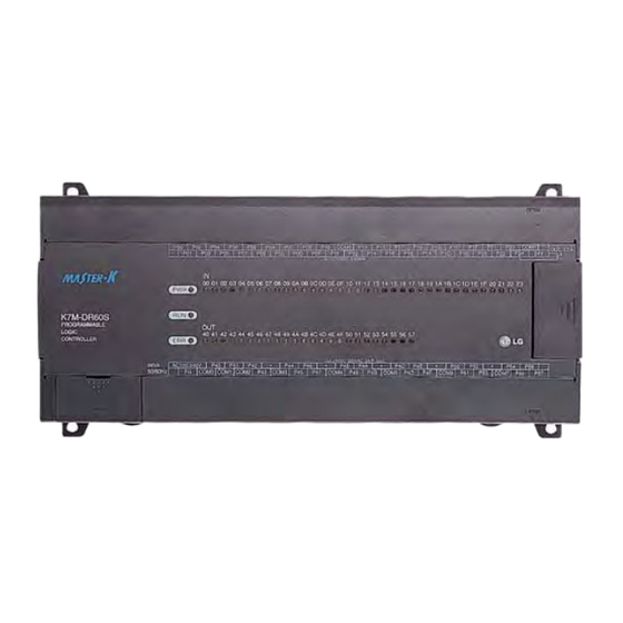
- Page 24 Chapter 4. Names of Parts Chapter 4. Names of Parts 4.1 Base Unit RS-485 (-) RS-485 (+) ⑩ ④ ⑤ 485+ 485- ⑧ BUILT_IN CNET ⑦ PAU/REM ② STOP ROM MODE ① ⑥ ③ ⑨ Name Indicates power supply to the system PWR LED On: When the supply is normal Off: When the supply is abnormal...
- Page 25 Chapter 4. Names of Parts Name Indicates base units drive mode RUN: Indicates program operation STOP: Stopped program operation Key switch mode creation PAU / REM: usage of each modules are as follows: ▶ PAUSE : temporary stopping program operation ▶...
- Page 26 Chapter 4. Names of Parts 4.1.1 10-point base unit 4.1.2 20-point base unit ④ ⑤ ① ② ③ Name Usage Terminal block for power supply Terminal blocks for power supply (AC 100V ~ 240V) FG circuit Frame ground Output terminal Output connecting terminal Input terminal Output connecting terminal...
- Page 27 Chapter 4. Names of Parts 4.1.3 30-points base unit 4.1.4 40-points base unit 4.1.5 60-points base unit 4 -4...
- Page 28 Chapter 4. Names of Parts 4.2 Expansion Module 4.2.1 Digital I/O Module 4.2.2 A/D・ ・ ・ ・ D/A Combination Module Names ⑤ ② RUN LED ① Analog Input Terminal ② Analog Input (Voltage/current) selecting jumper pin ③ ⑥ ⑦ Analog Output Terminal ④...
- Page 29 Chapter 4. Names of Parts 4.2.4 Option Modules Option modules are attached the expansion slot of main unit or expansion unit, and supplies optional functions such as memory expansion or real time clock. K80S series have two option modules – external memory module and RTC module.
- Page 30 Chapter 5 CPU Module Chapter 5. CPU 5.1 Specifications The following table shows the general specifications of the MASTER-K80S series Specifications K7M-DR10S K7M-DR20S K7M-DR30S K7M-DR40S K7M-DR60S Item Remarks K7M-DR10S/DC K7M-DR20S/DC K7M-DR30S/DC K7M-DR40S/DC K7M-DR60S/DC K7M-DT10S K7M-DT20S K7M-DT30S K7M-DT40S K7M-DT60S Program control method...
- Page 31 Chapter 5 CPU Module Item Specifications Remarks Internal PID control function Function block control, auto tuning, forced output, adjustable operation Function scan time, forward/reverse operation control Cnet I/F Function Master-K exclusive protocol support Common use with MODBUS protocol support KGLWIN port User’s protocol support Capacity 1 phase : 16 kHz, 1 channel...
-
Page 32: Cpu Part
Chapter 5 CPU Module 5.2 Operation Processing 5.2.1 Operation Processing Method 1) Cyclic operation A PLC program is sequentially executed from the first step to the last step, which is called scan. This sequential processing is called cyclic operation. Cyclic operation of the PLC continues as long as conditions do not change fo r interrupt processing during program execution. - Page 33 Chapter 5 CPU Module 2) Time driven interrupt operation method In time driven interrupt operation method, operations are processed not repeatedly but at every pre-set interval. Interval, in the MK80S series, can be set to between 0.001 to 6 sec. This operation is used to process operation with a constant cycle. 3) Event driven interrupt operation method If a situation occurs which is requested to be urgently processed during execution of a PLC program, this operation method processes immediately the operation, which corresponds to interrupt program.
- Page 34 Chapter 5 CPU Module 5.2.3 Scan Time The processing time from a 0 step to the next 0 step is called scan time. 1) Expression for scan time Scan time is the addition value of the processing time of scan program that the user has written, of the task program processing time and the PLC internal processing time.
- Page 35 Chapter 5 CPU Module 5.2.5 Timer Processing The MASTER-K series uses up count timers. There are 5 timer instructions such as on-delay (TON), off-delay (TOFF), integral (TMR), monostable (TMON), and re-triggerable (TRTG) timer. The measuring time range of 100msec timer is 0.1 ~ 6553.5 sec, and that of 10msec timer is 0.01 ~ 655.35 sec. Please refer the ‘MASTER-K programming manual’...
- Page 36 Chapter 5 CPU Module 3) Integral timer In general, its operation is same as on-delay timer. Only the difference is the current value will not be clear when the input condition of TMR instruction is turned off. It keeps the elapsed value and restart to increase when the input condition is turned on again.
- Page 37 Chapter 5 CPU Module 5) Retriggerable timer The operation of retriggerable timer is same as that of monostable timer. Only difference is that the retriggerable timer is not ignore the input condition of TRTG instruction while the timer is operating (decreasing). The current value of retriggerable timer will be set as preset value whenever the input condition of TRTG instruction is turned on.
- Page 38 Chapter 5 CPU Module 5.2.6 Counter Processing The counter counts the rising edges of pulses driving its input signal and counts once only when the input signal is switched from off to on. MASTER-K series have 4 counter instructions such as CTU, CTD, CTUD, and CTR. The maximum counter setting value is hFFFF ( = 65535).
- Page 39 Chapter 5 CPU Module 3) Up-down counter The current value is increased with the rising edge of up-count input signal, and decreased with the rising edge of down- count input signal. The counter output relay is turned on when the current value is equal or greater than the preset value. Up Input condition Cxxx Down Input condition...
- Page 40 Chapter 5 CPU Module 5.3 Program 5.3.1 Classification of program All functional elements need to execute a certain control process are called as a ‘program’. In MASTER-K series, a program is stored in the RAM mounted on a CPU module or flash memory of a external memory module. The following table shows the classification of the program.
- Page 41 Chapter 5 CPU Module 5.3.3 Interrupt function When an interrupt occurs, the CPU module will stop the current operation and execute the corresponding interrupt routine. After finish the interrupt routine, the CPU resume the sequence program from the stopped step. MASTER-K series provides 2 types of interrupt.
- Page 42 Chapter 5 CPU Module 1) parameter setting 2) Time driven interrupt TDI occurs periodically with the constant interval assigned in parameter setting. The interrupt routine of TDI starts with the TDINT instruction and ends with the IRET instruction. When multiple interrupt factors occur simultaneously, interrupt routines are executed according to the priority given to the each interrupt. If an interrupt factor has higher priority occurs while other interrupt of lower priority is executing, the interrupt routine of lower priority will be stopped and the interrupt of higher priority will be executed first.
- Page 43 Chapter 5 CPU Module 5.3.4 Error Handling 1) Error Classification Errors occur due to various causes such as PLC system defect, system configuration fault or abnormal ope ration result. Errors are classified into fatal error mode, which stops system operation for system stability, a nd ordinary error mode, which continues system operation with informing the user of its error warning.
- Page 44 Chapter 5 CPU Module 5.4 Operation Modes The CPU module operates in one of the four modes - the RUN, STOP, PAUSE and DEBUG mode. The following descri bes the PLC operation processing in each operation mode. 5.4.1 RUN mode In this mode, programs are normally operated.
- Page 45 Chapter 5 CPU Module 5.4.2 STOP mode In this mode, programs are not operated. 1) Processing when the operation mode changes. The output image area is cleared and output refresh is executed. 2) Operation processing contents (1) I/O refresh is executed. (2) Normal or abnormal operation and mounting conditions of the loaded module are checked.
- Page 46 Chapter 5 CPU Module 3) Debug operation conditions • Two or more of the following four operation conditions can be simultaneously specified. Operation conditions Description Executed by the one Executes just an operation unit ( one step) (step operation) Executed to the Executes user program until the specified step (break point) specified breakpoint.
- Page 47 Chapter 5 CPU Module 3) Remote operation mode change Remote operation mode change is available only when the operation mode is set to the remote STOP mo de (i.e., the mode setting switch position is in the STOP→ PAU/REM’). Mode change using Mode setting Mode change by the Mode Change...
- Page 48 Chapter 5 CPU Module 5.5 Functions 5.5.1 Self-diagnosis 1) Functions (1) The self-diagnosis function permits the CPU module to detect its own errors. (2) Self-diagnosis is carried out when the PLC power supply is turned on and when an error occurs the PLC i s in the RUN state.
- Page 49 Chapter 5 CPU Module 5.5.2 I/O Force On/Off function It is possible to input/output a designated data regardless of the result of program operation. This function is useful to check operation of the input/output modules and wiring between the output modules and external devices. 1) Force On/Off setting method.
- Page 50 Chapter 5 CPU Module Set ‘forced I/O data’ by bit Set ‘forced I/O data enable’ by bit When forced I/O set enables, forced I/O function is executing. Click 5-21...
- Page 51 Chapter 5 CPU Module 2) Special data register for forced I/O set The contents of forced I/O setting is registered to special data register as below. It is possible to use ‘forced I/O function’ to program. Item Special Device All Forced I/O enable M1910 Forced I/O enable by bit D4700 ~ D4731...
- Page 52 Chapter 5 CPU Module 5.5.3 Direct I/O Operation function This function is usefully available when an input junction state is directly read during execution of a program and used in the operation, or the operation result is directly output to an output junction. Direct input/output is executed by use of the ‘IORF’...
- Page 53 Chapter 5 CPU Module 5.6 Memory Configuration The CPU module includes two types of memory that are available by the user. One is program memory, which is used to store the user programs written to implement a system by the user. The other is data memory, which sto res data during operation.
- Page 54 Chapter 5 CPU Module 5.7 I/O No. Allocation Method I/O No. allocation means to give an address to each module in order to read data from input modules and output data to output modules. Max. 3 expansion module is available Mounting module No.
- Page 55 Chapter 5 CPU Module 5.8 Built-in Flash Memory MK80S series includes a built-in flash memory to store user program. Also, user can set the PLC automatically executes the user program of flash memory when the PLC is turned on. It is similar with the ROM operation of other PLCs, but it is different that no external memory is required.
- Page 56 Chapter 5 CPU Module 5.8.2 Usage Set the base unit to the STOP mode. Select the ‘Flash memory’ of on-line menu, the following window shows. 1) read read the program and parameter to CPU memory from fresh memory 2) write write the program and parameter to fresh memory from CPU memory 3) verify verify the program and parameter between CPU memory and fresh memory...
- Page 57 Chapter 5 CPU Module 4) dip switch for operating flash memory. Dip switch position Description upper switch is for Cnet. When power is on, the program saved in the flash memory operates. ROM MODE Upper switch is for Cnet. CPU recognizes that there is no program in the flash memory, and starts to drive program from RAM.
- Page 58 Chapter 5 CPU Module 5.9 External Memory Module MK80S series supplies external memory module for the user to save programs safely or download a program on the system and use it in case of a program is damaged. 5.9.1 Structure Installation connector 5.9.2 Usage 1) Saving the user’s program on the external memory module.
- Page 59 Chapter 5 CPU Module 2) Run the PLC with a program of external memory module (1) Turn the power of the base unit off. (2) Install the memory module (When only base unit is used, connect to the expansion connector of the base unit. And when expansion unit is used, connect to the expansion connector of the last connected expansion unit).
- Page 60 Chapter 5 CPU Module 5.10 RTC Module MK80S series supplies RTC(Real Time Clock) module for the time-scheduling control. To use RTC function with K80S series, the RTC operation module should be attached to the expansion slot of main unit or expansion/special function unit. Clock operation by the RTC function is continued with a battery or super capacitor when the CPU is powered off.
- Page 61 Chapter 5 CPU Module 3) Read / write RTC data a) Read RTC data The current RTC data Description Data Memory Area (Word) (BCD format) Upper byte Lower byte F053 Lower 2 digits of year Month h9812 F054 Hour h2219 F055 Minute Second...
- Page 62 Chapter 5 CPU Module 5.11 Battery 1) Specifications Item Specifications Normal voltage DC 3.0 V Warranty life time 5 years Application Programs and data backup, and RTC runs in power failure Specifications Lithium Battery, 3V φ 14.5 X 26 External dimension (mm) 2) Handling Instructions (1) Don’t heat or solder its terminals.
- Page 63 6.1 Input / Output Specifications Digital input that offers to MASTER-K80S series are made to use both of electric current sink and electric current source. To keep use coil load as an output module, maximum opening and shutting frequency is 1 second on and 1 second off.
- Page 64 Chapter 6 Input and Output Modules 6.2 Digital Input Specification 6.2.1 Base unit 1) Specification Base unit Model K7M-DR10S K7M-DR30S K7M-DR40S K7M-DR60S K7M-DR20S K7M-DR10S/DC K7M-DR20S/DC K7M-DR30S/DC K7M-DR40S/DC K7M-DR60S/DC Specification K7M-DT10S K7M-DT30S K7M-DT40S K7M-DT60S K7M-DT20S Number of input points 6 points 12 points 18 points 24 points...
- Page 65 Chapter 6 Input and Output Modules 3) Input wiring Base unit’s wiring method is as follows. DC input specifications offered by K80S is to be used for both electric current sink and electric current source. (1) 10-points base unit DC24V (2) 20-points base unit DC24V 6-3...
- Page 66 Chapter 6 Input and Output Modules (3) 30-point base unit DC24V (4) 40-point base unit DC24V DC24V 6-4...
- Page 67 Chapter 6 Input and Output Modules (5) 60-point base unit DC24V DC24V 6-5...
- Page 68 Chapter 6 Input and Output Modules 4) Example of external devices. To connect with external device of DC output type into DC input module, wire depending on the type of the external device as shown. External device Input module Relay Sensor Power for sensor...
- Page 69 Chapter 6 Input and Output Modules 6.2.2 Expansion Module Specifications Model Expansion Module Specification G7E-DR10A Number of input points 6 points Insulation method Photo coupler Rated input voltage DC12 / 24V Rated input current 4.5 / 9 mA Operating voltage range DC10.2 ~ 28.8V (ripple: less than 5%) Max.
- Page 70 Chapter 6 Input and Output Modules 6.3 Digital Output Specification 6.3.1 Base unit (Relay Output) Specification Model Base Unit K7M-DR10S K7M-DR20S K7M-DR30S K7M-DR40S K7M-DR60S K7M-DR10S/DC K7M-DR20S/DC K7M-DR30S/DC K7M-DR40S/DC K7M-DR60S/DC Specifications Output point 4 points 8 points 12 points 16 points 24 points Insulation method Relay insulation...
- Page 71 Chapter 6 Input and Output Modules 3) Output wiring (1) 10-points base unit AC100-240V COM0 COM1 COM2 COM3 • (2) 20-points base unit L L L DC5V DC24V AC110/220V 6-9...
- Page 72 Chapter 6 Input and Output Modules (2) 30-point base unit L L L DC5V DC24V AC110/220V (3) 40-point base unit L L L DC24V DC5V DC24V AC110/220V 6-10...
- Page 73 Chapter 6 Input and Output Modules (4) 60-point base unit DC5V DC24V AC110/220V DC24V DC24V 6-11...
- Page 74 Chapter 6 Input and Output Modules 6.3.2 Base unit (Transistor Output) 1) Specification Model Base Unit Specifications K7M-DT10S K7M-DT20S K7M-DT30S K7M-DT40S K7M-DT60S Output point 4 points 8 points 12 points 16 points 24 points Insulation method Photo Coupler insulation Rated load voltage/current DC12 / 24V Operating load voltage DC10.2 ~ 26.4V...
- Page 75 Chapter 6 Input and Output Modules (3) Wiring Diagram 10-point base unit 20-point base unit 30-point base unit 6-13...
- Page 76 Chapter 6 Input and Output Modules 40-point base unit 60-point base unit 6-14...
- Page 77 Chapter 6 Input and Output Modules 6.3.3 Expansion Module 1) Specifications Model Expansion Module Specifications G7E-DR10A Output point 4 points Insulation method Relay insulation Rated load DC24V / 2A (r/load), AC220V / 2A (COS Ψ = 1) / 1 point 5A / 1COM Voltage/current Min.
- Page 78 Chapter 7 Usage of Various Functions Chapter 7 Usage of Various Functions 7.1 Built-in Functions 7.1.1 High-speed counter function This chapter describes the specification, handling, and programming of built-in high speed counter of MK80S. The built-in high speed counter of MK80S(hereafter called HSC) has the following features; 3 counter functions as followings - 1-phase up / down counter : Up / down is selected by user program...
- Page 79 Chapter 7 Usage of Various Functions Names of wiring terminals Counter input Preset input ① ② ③ ④ BUILT_IN CNET ROM MODE COM0 Terminal No. Names Usage φ A 24V A Phase input terminal ① φ B 24V B Phase input terminal ②...
- Page 80 Chapter 7 Usage of Various Functions Wiring instructions A high speed pulse input is sensitive to the external noise and should be handled with special care. When wiring the built- in high speed counter of MK80S, take the following precautions against wiring noise. (1) Be sure to use shielded twisted pair cables.
- Page 81 Chapter 7 Usage of Various Functions Instruction When use the built-in high speed counter of K80S, the HSC instruction should be used. The instruction format of HSC is as following; PV ( SV ( When the value of operation mode (D4999), PV or SV is not proper, the instruction error flag (F110) turns on and the HSC instruction is not executed.
- Page 82 Chapter 7 Usage of Various Functions EN input (Counter enable) When the EN input turns on, the counter starts counting pulse. When the EN is off, the counting is stopped and the current value of high speed counter is cleared as 0. 2) U/D input (Up/down) When the U/D input is off, the high speed counter operates as up counter.
- Page 83 Chapter 7 Usage of Various Functions 8) example program (1) 1-phase operation mode (U/D by program : D4999 = h1010) U/D : set by sequence program (M001) PR : set by external PR input Ladder diagram h1010 D4999 D0000 01000 D0010 M000 M001...
- Page 84 Chapter 7 Usage of Various Functions (2) 1-phase operation mode (U/D by B phase : D4999 = h1100) U/D : set by external input (B-phase input) PR : set by sequence program (M002) Ladder diagram F012 h1100 D4999 M000 M001 PV 00100 M002 SV 01000...
- Page 85 Chapter 7 Usage of Various Functions (3) 2-phase operation mode (1 Multiplication Operation : D4999 = h2011) U/D : set automatically by the phase difference between A and B phase PR : set by external PR input Multiplication : 1 Ladder diagram F012 h2011...
- Page 86 Chapter 7 Usage of Various Functions 4) 2-phase operation mode (2 Multiplication Operation : D4999 = 2012) U/D : set automatically by the phase difference between A and B phase PR : set by external PR input Multiplication : 2 times Ladder diagram F012 h2012...
- Page 87 Chapter 7 Usage of Various Functions (5) 2-phase operation mode (4 Multiplication Operation : D4999 = h2014) U/D : set automatically by the phase difference between A and B phase PR : set by external PR input Multiplication : 4 times Ladder diagram F012 h2014...
- Page 88 Chapter 7 Usage of Various Functions 7.1.2. Pulse Output Function In the transistor output type of MK80S, the pulse output function - maximum 2Kpps - is internalized. By using this function with stepping motor or servo motor driver, MK80S is applicable to a simple positioning system. 1) Usage of the Pulse Output Transistor output type of MK80S outputs the signals of pulse and direction in an output contact point through the instruction (PULSOUT).
- Page 89 Chapter 7 Usage of Various Functions 2) Functional Specification Specification Item No. of output 1 point Output type Pulse Output velocity Max 2Kpps, Min 50pps Output pulse 0 ~ 2147483647 Execution type of the increasing/decreasing velocity Designation of acceleration Type of the direction designation Right/opposite direction pulse output Load power supply DC 12V/24V...
- Page 90 Chapter 7 Usage of Various Functions 3) Names of parts Stepping motor AC100-240V COM0 COM1 COM2 Motor driver ③ ① ④ ② Output direction Output pulse Terminal No. Usage Names Pulse output Pulse output terminal of right direction ① COM0 Common Pulse output common terminal ②...
- Page 91 Chapter 7 Usage of Various Functions 4) Internal circuit and external wiring +12/24V – power supply input(12/24V pulse output – P41 - direction output COM0 – output common Internal circuit K7M-DT30S Motor Transistor output driver(24V) power supply external wiring Remark Be careful about the counter plan of the noise during the wiring in the pulse output.
- Page 92 Chapter 7 Usage of Various Functions 5) The setting of pulse out parameter The setting of pulse out parameter set KGLWIN. Setting windows is as below. It is possible to set 40 operational pattern. When click the pattern no. parameter setting window is displayed as bellow 6) parameter explanation (1) operational pattern No.
- Page 93 Chapter 7 Usage of Various Functions b) continuous operation setting of contact for infinitive operation c) emergency stop setting of contact for emergency stop (7) The number of acceleration pulse Automatically calculate at KGL-WIN if the maximum pulse and slop are set by user Calculation method is as below The number of acceleration pulse = [(maximum pulse –...
- Page 94 Chapter 7 Usage of Various Functions 7) pulse out operation explanation Condition 1) Set up as acceleration slop = 1, max. frequency = 1000, no of pulse out = 5000. ← If as acceleration slop = 1, 1 pulse is output on the 1st step (velocity: 50pps). Pulse velocity is 50pps, so time consuming is 20ms.
- Page 95 Chapter 7 Usage of Various Functions Condition 2 Set up as acceleration slop = 2, max. frequency = 1000, no of pulse out = 5000. ← If I/D velocity inclination is 2, 2 pulses are output on the 1st step(velocity: 50pps). Pulse velocity is 50pps.
- Page 96 Chapter 7 Usage of Various Functions 8) instruction Available Device Flag Instructions Steps Inte- Error Zero Carry (F110) (F111) (F112) DUTY Pattern no. PLSOUT Output pulse count no. Output pulse contact (1) Functions - ‘n’ designates pattern no. which is registered at parameter. - S1 designates device name which will be stored output pulse count no.
- Page 97 Chapter 7 Usage of Various Functions (3) instruction Error List Contents Error status Treatment Normal Other PLSOUT instruction pulsating. Change the other PLCOUT program. Velocity designation error (more than 2000, not a Velocity designation adjustment multiple of 50, designated 0) The no.
- Page 98 Chapter 7 Usage of Various Functions 9) Output Direction Input type of servo motor driver or stepping motor driver is subdivided into 2. Output direction of control can be selected in the pulse output parameter. (1) Selecting method of output direction When driver gets input forward direction pulse and reverse direction pulse contact point, and the forward/reverse direction signals one levels.
- Page 99 Chapter 7 Usage of Various Functions Driver gets input forward direction pulse and reverse direction pulse through different contact points. Forward direction (P50) Reverse direction (P51) Forward operation Reverse operation Target velocity = 1Kpps Forward direction Target position 5000 Reverse dir. start point Time Target position=10000...
- Page 100 Chapter 7 Usage of Various Functions 7.1.3. Pulse Catch Function In the base unit, 8 points of pulse catch input contact points(P000 ~ P007) are internalized. Through using this contact point short pulse signal, short as 0.2ms, can be taken which can not be executed by general digital input. 1) Usage When narrow width of pulse signal is input, a trouble occurs which can not be detected by general digital input, so the operation does not perform as user's intention.
- Page 101 Chapter 7 Usage of Various Functions Remark 1) 8 points can be used to designate the pulse catch input. The input address is from P000 to P007. 2) General digital input operates if it is not designated as pulse catch input. 7-24...
- Page 102 Chapter 7 Usage of Various Functions 7.1.4. Input Filter Function External input of MK80S selects input on/off delay time from the range of 0-15ms of KGLWIN. Credibility secured system may be established by adjustment of input correction no. through using environment. 1) Usage Input signal status affects to the credibility of system in where noise occurs frequently or pulse width of input signal affects as a crucial factor.
- Page 103 Chapter 7 Usage of Various Functions 7.1.5 PID control function 1) Introduction This chapter will provide information about the built-in PID (Proportional Integral Differential) function of MK80S Basic Unit. The MK80S series does not have separated PID module like MK300S and MK1000S series, and the PID function is integrated into the Basic Unit.
- Page 104 Chapter 7 Usage of Various Functions 2) Specification (1) Control operation Proportional operation (P operation) (a) P action means a control action that obtain a manipulate value which is proportional to the deviation (E : the difference between SV and PV) (b) The deviation (E) is obtained by multiplying a reference value to the actual difference between SV and PV.
- Page 105 Chapter 7 Usage of Various Functions Fig. 2.2 When the proportional constant (Kp) is large Fig. 2.3 When the proportional constant (Kp) is small Integral operation (I operation) (a) With integral operation, the manipulate value (MV) is increased or decreased continuously in accordance time in order to eliminate the deviation between the SV and PV.
- Page 106 Chapter 7 Usage of Various Functions (b) Integral action when a constant deviation has occurred is shown as the following Fig. 2.4. Fig. 2.4 The integral action with constant deviation (c) The expression of I action is as following; ∫ As shown in the expression, Integral action can be made stronger or weaker by adjusting integration time (Ki) in I action.
- Page 107 Chapter 7 Usage of Various Functions Fig. 2.6 The system response when a short integration time given Derivative operation (D action) (a) When a deviation occurs due to alteration of SV or external disturbances, D action restrains the changes of the deviation by producing MV which is proportioned with the change velocity (a velocity whose deviation changes at every constant interval) in order to eliminate the deviation.
- Page 108 Chapter 7 Usage of Various Functions (d) The expression of D action is as following; × (e) Derivative action is used only in PID action in which P and I actions combine with D action. PID action (a) PID action controls the control object with the manipulation quantity produced by (P+I+D) action (b) PID action when a given deviation has occurred is shown as the following Fig.
- Page 109 Chapter 7 Usage of Various Functions (c) Fig 2.10 shows examples of process control by forward and reverse actions, respectively. Fig. 2-10 PV of forward / reverse action Reference value In general feedback control system shown as the Figure 2-10, the deviation value is obtained by the difference of PV and SV.
- Page 110 Chapter 7 Usage of Various Functions The figure 2.11 shows the variation of PV according to the several different reference values (b). As shown in the Fig. 2.11, the small reference value produces small deviation value, and it makes the control system response be slow.
- Page 111 Chapter 7 Usage of Various Functions Time Time MV (without windup) MV (with windup) Integral term Proportional term There are several methods to avoid the windup of actuator. The most popular two methods are adding another feedback system to actuator, and using the model of actuator. The Fig. 2-13 shows the block diagram of the anti- windup control system using the actuator model.
- Page 112 Chapter 7 Usage of Various Functions K × Td E = -PV Actuator model Actuator E = SV-PV – k / Ti 1 / Tt Fig. 2-13 The block diagram of anti-windup control system Tt = 3 Tt = 2 Tt = 1 Time Fig.
- Page 113 Chapter 7 Usage of Various Functions e = (SV – PV) : deviation value The digitized formula is as following; − h : sampling period D control The continuous formula of derivative term is as following; × − N : high frequency noise depression ration y : the object to be controlled (PV) The digitized formula is as following (Use Tustin approximation method) −...
- Page 114 Chapter 7 Usage of Various Functions Remarks 1.Refer the KGLWIN manual for the parameter setting. (1) Parameter setting and explanation PID8 instruction parameter setting and explanation. (a) Scan time scan time is the period of reading data (sampling), and also 10 times scaled up. Generally, it should be synchronized with external trigger input (EN input of function block) to perform proper PID operation.
- Page 115 Chapter 7 Usage of Various Functions (g) Proportional gain The MK80S can handle only integer, not the floating point type. Therefore, to enhance the accuracy of PID operation, the PID8 instruction is designed to input the P_GAIN data as the 100 times scaled up. For example, if the designated P_GAIN is 98, actual input data of P_GAIN should be 9800.
- Page 116 Chapter 7 Usage of Various Functions PID8AT instruction parameter setting and explanation. (a) Scan time S_TIME is the period of reading data (sampling), and 10 times scaled up for more precious operation. Generally, it should be synchronized with external trigger input to perform proper PID operation. The range of sampling time is 0.1 ~ 10 seconds, and actual input range is 0 ~ 100.
- Page 117 Chapter 7 Usage of Various Functions Error codes of auto-tuning function block (PID8AT) The following table shows error codes and descriptions of PID8AT instruction. Error code Description Countermeasure (STAT output) Normal operation SV is out of range Change the SV within 0 ~ 4000 It may caused by fault of A/D module.
- Page 118 Chapter 7 Usage of Various Functions 2) instruction (1) PID8 Available device Flag Instruction Step no. Error Zero Carry Integ (F110) (F111) (F112) PID8 Flag Set It turns ‘on’ when designation area is over and Error (F110) the instruction isn’t executed. PID8 Designation area Registration No.
- Page 119 Chapter 7 Usage of Various Functions (2) PID8AT Available device Flag Instruction Step no. Error Zero Carry Integ (F110) (F111) (F112) PID8 Flag Set It turns ‘on’ when designation area is over and Error (F110) the instruction isn’t executed. PID8 Designation area Registration No.
- Page 120 Chapter 7 Usage of Various Functions 6) Program Example (1) System configuration G7F-ADHA K80S Base unit KGLWIN MV: DC4~20mA (V2.0 or later) RS-232C (1~5V) PV: DC4~20mA (1~5V) Signal transforming device Temp. Sensor Electric oven (0 ~ 200°C) Heater Transformer (2) Initial setting PID operation parameters ►...
- Page 121 Chapter 7 Usage of Various Functions (3) Program Explanation Use only PID operation (without A/T function) (a) Convert the measured temperature (0 ~ 250°C) to current signal (4 ~ 20mA), and input the current signal to the channel 1 of A/D module. Then, the A/D module converts the analog signal to digital value (0 ~ 4000) (b) PID8 instruction will calculate manipulate value (MV : 0 ~ 4000) based on PID parameter settings (P_GAIN, I_TIME, D_TIME, etc.) and PV from A/D module.
- Page 122 Chapter 7 Usage of Various Functions (4) parameter setting and Program In case of using PID function only. PID execution completes at 10 second each time At that time bit 0 of D200 turns on and output MV value. F095 is 10 second clock F095 is 10 second clock PID execution scan time is equal to input clock certainly PID execution scan time is equal to input clock certainly...
- Page 123 Chapter 7 Usage of Various Functions In case of using combined function of PID operation and Auto tuning. This program is an example of PID operation performing with computed P,I,D values by the auto tuning performing. It is performed in 80% of auto tuning SV, PID process is performed from 80% of SV. PID execution scan time should be equal to input clock certainly As a result of PID8AT execution, Proportional gain(P),Differential time(D),Integral...
- Page 124 Chapter 7 Usage of Various Functions When PID auto tuning ends, PID8 and PID8AT input period should be equal to execution scan time M100 turns on which is designated at parameter 7-47...
- Page 125 Chapter 7 Usage of Various Functions 7.1.6 External Interrupt Function In MK80S Series can perform max 8 points of external contact interrupt by using input of base unit without special interrupt module. 1) Usage This function is useful to execute a high speed execution regardless of scan time. 2) Operating explanation External input signal Scan program...
- Page 126 Chapter 7 Usage of Various Functions (4) Designate contact point, no. of priority and movement condition of the task program which is moved by interrupt inputting. Time driven Interrupt execution periodic set xecuting interrupt input e condition interrupt input contact No. ◎...
- Page 127 Chapter 7 Usage of Functions 7. 2 Special module 7.2.1 A/D·D/A Combination module 1) Performance specification The performance specification of the analog mixture module are following. Item Specifications Voltage DC 0∼10V (input resistance more than 1 ㏁) DC 0∼20 ㎃ (input resistance 250Ω) Input range Classified by Current...
- Page 128 Chapter 7 Usage of Functions 2) Names of parts and functions Explain about names of parts and functions Contents. RUN LED ① Indicate the operating status the G7F-ADHA Analog input terminal Voltage Input Current input CH0 (INPUT) CH0 (INPUT) I0 COM0 I0 COM0 ②...
- Page 129 Chapter 7 Usage of Functions 3) Parameter setting The same or less than KGLWIN V2.13 The same or more than KGLWIN V2.14 4) Reading A/D conversion value & Writing D/A conversion value A/D conversion value and D/A conversion value stores special data register as following. The table which is shown below is possible to use under the same or less than K80S CPU ROM V1.3.
- Page 130 Chapter 7 Usage of Functions 5) Scaling function This function convert automatically range when the inout/output range is not matched In case that input/output is current , this function is useful that external equapment’ range is not matched each other. (MK80S series converts range automatically as following : 0 ~ 20mA √...
- Page 131 Chapter 7 Usage of Functions 6) Wiring (1) Caution for wiring ▶Make sure that external input signal of the mixture module of AC and analog I/O is not affected by induction noise or occurs from the AC through using another cable. ▶Wire is adopted with consideration about peripheral temperature and electric current allowance.
- Page 132 Chapter 7 Usage of Functions 7) I/O converstion characteristics (1) Analog input characteristics a) Voltage input 4000 2004 2003 2002 2001 2000 2000 Input Voltage Analog input voltage A/D conversion characteristics (voltage input) In voltage input, digital amount 0 is output by 0V input and 4,000 is output by 10V input. Therefore input 2.5mV equals to digital amount 1, but value less than 2.5mV can’t be converted.
- Page 133 Chapter 7 Usage of Functions (2) Analog output characteristics a) Voltage output 2.5 ㎷ 5.0025 2000 2001 2002 200 Digital input 0V 0 2000 4000 Digital input value D/A conversion characteristic (voltage output) Input of digital amount 0 outputs analog amount 0V, 4000 does 10V. Digital input 1 equals to 2.5mV of analog amount. b) Current output 20 ㎃...
- Page 134 Chapter 7 Usage of Functions 8) Program example (1) Distinction program of A/D conversion value a) Program explanation - When digital value of channel 0 is less than 2000, P090 is on. - when digital value of channel 0 is more than 3000, P091 is on. - When digital value of channel 0 is more or same than 2000 or lesser than 3000, P092 is on.
- Page 135 Chapter 7 Usage of Functions (2) Program which controls speed of inverter by analog output voltage of 5 steps a) Program explanation -.When P80 becomes On, 2000 (5V) is output. -. When P81 becomes On, 2400 (6V) is output. -.When P82 becomes On, 2800 (7V) is output. -.When P83 becomes On, 3200 (8V) is output.
- Page 136 Chapter 7 Usage of Functions 7.2.2 A/D Conversion module 1) Performance specifications The performance specifications of the analog input module are following. Item Specifications 0∼10VDC ( input resistance more than 1 ㏁ ) Voltage DC 4∼20 ㎃ ( input resistance 250Ω ) Current DC 0∼20 ㎃...
- Page 137 Chapter 7 Usage of Functions 2) Names of parts and functions The Names of parts and functions of the analog input module are following. Contents RUN LED ① Indicate the operating status the G7F-AD2A Analog input terminal Voltage input Current input ④...
- Page 138 Chapter 7 Usage of Functions 3) Parameter setting 4) Reading A/D conversion value A/D conversion value stores special data register as following. * It is possible to use A/D conversion module more than K80S ROM V1.4 Special data Explanation Remark register D4980 A/D conversion value of channel 0 stores...
- Page 139 Chapter 7 Usage of Functions 6) Wiring (1) Caution for wiring ▶Make sure that external input signal of the mixture module of AC and analog I/O is not affected by induction noise or occurs from the AC through using another cable. ▶Wire is adopted with consideration about peripheral temperature and electric current allowance.
- Page 140 Chapter 7 Usage of Functions 7) Analog/Digital conversion characteristics (1) Analog input characteristics a) Voltage input 4000 2004 2003 2002 2001 2000 2000 Voltage Input Analog Input Voltage A/D Conversion Characteristics (Voltage Input) In voltage input, digital amount 0 is output by 0V input and 4,000 is output by 10V input. Therefore input 2.5mV equals to digital amount 1, but value less than 2.5mV can’t be converted.
- Page 141 Chapter 7 Usage of Functions 8) Program example (1) Distinction program of A/D conversion value(Analog input range: DC4∼20 ㎃, 0~10VDC) a) Program explanation -When digital value of channel 0 is the same or more than 2000 and the same or less than 3000, P090 is on. -When digital value of channel 1 is the same or more than 2000 and the same or less than 3000, P091 is on.
- Page 142 Chapter 7 Usage of Functions 7.2.3 Analog timer 1) Performance specification The performance specification of the analog timer module are following. Item Specification Number of channels Output value range 8 Bit (Digital output range: 0 ∼ 200) Setting type Setting by variable resistance Accuracy of timer ±2.0% (Accuracy about max.
- Page 143 Chapter 7 Usage of Functions 3) Reading A/T conversion value A/T conversion value stores special data register as following. Special data Explanation remark register D4966 A/T conversion value of channel 1 stores Expansion A/T module #1 D4967 A/T conversion value of channel 2 stores Expansion A/T module #1 D4968 A/T conversion value of channel 3 stores...
- Page 144 Chapter8 Communication Function Chapter 8 Communication Function 8.1 Dedicated Protocol Communication 8.1.1 Introduction MK80S’s built-in Cnet communication uses only MK80S base unit for a dedicated communication. That is, it doesn’t need a separate Cnet I/F module to facilitate the user-intended communication system by utilizing reading or writing of any area in CPU, and monitoring function.
- Page 145 Chapter8 Communication Function 8.1.2 System configuration method According to the method of connection, the system using MK80S built-in communication can be composed. 1) Connecting system configuration (link between MASTER-K’s) (1) 1:1 connection with general PC a) Communication program made by C or BASE computer language on the user’s computer, or utility program like MMI software can be used.
- Page 146 Chapter8 Communication Function (2) 1:1 connection with a monitoring device like PMU PMU(LGIS) K80S base unit RS-232C interface MK80S base unit Pin assignment and direction Pin No. Pin no. Signal RXD1 TXD1 RXD2 TXD2 Female Type...
- Page 147 Chapter8 Communication Function (3) 1:1 connection with other MK80S For the detailed information, refer to 8.1.7 “1:1 Dedicated Protocol Communication.” K80S base unit K80S base unit RS-232C interface MK80S base MK80S base unit unit Pin assignment and direction Pin no. Pin no.
- Page 148 Chapter8 Communication Function 8.1.3 Frame Structure 1) Base Format (1) Request frame(external communication device → MK80S base unit) (Max. 256 Bytes) Header Station Command Tail Frame check Command Structurized data area (ENQ) number type (EOT) (BCC) (2) ACK Response frame (MK80S base unit → external communication device, when receiving data normally) (max.
- Page 149 Chapter8 Communication Function Remark 1) The numerical data of all frames are ASCII codes equal to hexadecimal value, if there’s no clear statement. The terms in hexadecimal are as follows. • Station No. • When the main command is R(r) or W (w) and the command type is numerical (means a data type) •...
- Page 150 Chapter8 Communication Function 8.1.4 List of commands Command list for communication. Division Command Treatment Main command Command type Item Code ASCII code Code ASCII code Individual Reads device of Bit, Word and type. r(R) 5353 Reading reading (H52) device Reads device Word in block unit. Continuos r(R) 5342...
- Page 151 Chapter8 Communication Function 8.1.5 Data type It’s possible to read and write device in built-in communication. When device is used, be aware of data type. 1) Data type of variable • Available types of device : P,M,L,K,C,T,D,S,F • When variable is used, attach ‘%’(25H) in front of the marking characters. Data type Marking characters Examples...
- Page 152 Chapter8 Communication Function 8.1.6 Execution of commands 1) Individual reading of device(RSS) (1) Introduction This is a function that reads PLC device specified in accord with memory data type. Separate device memory can be read up to 16 at a time. (2) PC request format Station Command...
- Page 153 Chapter8 Communication Function Remark Numerical data of frame(Ex.) is hex value, and "H" is unnecessary during preparing real frame. Device data type of each must be same. If data type of the first block is WORD, and the second block is BIT, error occurs.
- Page 154 Chapter8 Communication Function Ex.2 If number of data is H04 and the data is H12345678, ASCII code converted value of this is "31 32 33 34 35 36 37 38," and this contents is entered in data area. Name directly, highest value is entered first, lowest value last. Remark 1) If data type is Bit, data read is indicated by bytes of hex.
- Page 155 Chapter8 Communication Function ← Computer request format (PC → MK80S Base Unit) Command Number of Variable Format Frame Format name Header Station No. Command Devicelength Format name Tail type blocks length name check Ex. of frame %MW20 %PW001 H254D57 H25505730 ASCII value H3031 H5353...
- Page 156 Chapter8 Communication Function 2) Continuous reading(RSB) of device (1) Introduction This is a function that reads the PLC device memory directly specified in accord with memory data type. With this, data is read from specified address as much as specified continuously. (2) PC request format Number of data Station...
- Page 157 Chapter8 Communication Function (3) MK80S Base Unit response format (MK80S of ACK response) Command Number of Number of Frame Format name Header Station No. Command data Tail type blocks data check R(r) H1122 Ex. of frame H3130 H52(72) H5342 H3031 H3134 H31313232 ASCII value...
- Page 158 Chapter8 Communication Function (4) Response format (NAK response) Error code Format name Header Station No. Command Command type Tail Frame check (Hex 2 Byte) H1132 Ex. of frame H3130 H5342 H31313332 ASCII value Item Explanation When command is lowercase(r), only one lower byte of the value resulted by adding 1 Byte each to ASCII values from NAK to ETX is converted into ASCII and added to BCC, and sent.
- Page 159 Chapter8 Communication Function 3) Individual writing of device(W(w)SS) (1) Introduction This is a function that writes the PLC device memory directly specified in accord with memory data type. (2) PC request format Frame Command Number of Device Tail Format name Header Station No.
- Page 160 Chapter8 Communication Function Remark 1) Device data types of each block must be the same. 2) If data type is Bit, the data to be written is indicated by bytes of hex. Namely, if Bit value is 0, it must be indicated by H00(3030), and if 1, by H01(3031).
- Page 161 Chapter8 Communication Function (5) Example This example supposes that "HFF" is written in M230 of station No. 1 and BCC value is checked. ① Computer request format (PC → MK80S Base Unit) Frame Command Number of Tail Format name Header Station No. Command Device Length Device Name Data check...
- Page 162 Chapter8 Communication Function 4) Continuous writing of device(WSB) (1) Introduction This is a function that directly specifies PLC device memory and continuously writes data from specified address as much as specified length. (2) Request format Number of data Frame Format Station Comman Comma...
- Page 163 Chapter8 Communication Function (3) Response Format (ACK response) Tail Frame check Format name Header Station No. Command Command type Frame (Example) W(w) ASCII value H3130 H57(77) H5342 Item Explanation When command is lowercase(r), only one lower byte of the value resulted by adding 1 Byte each to ASCII values from ACK to ETX is converted into ASCII and added to BCC, and sent.
- Page 164 Chapter8 Communication Function (5) Example This example supposes that 2 byte HAA15 is written in D000 of station No. 1 and BCC value is checked. ① Computer request Format (PC → MK80S Base Unit) Frame Station Command Device Number of Data Tail Format name...
- Page 165 Chapter8 Communication Function 5) Monitor register(X##) (1) Introduction Monitor register can separately register up to 10 in combination with actual variable reading command, and carries out the registered one through monitor command after registration. (2) PC request Format Registration Frame Registration Format Tail Format name...
- Page 166 Chapter8 Communication Function (4) Response Format (NAK response) Registration Error code Frame Tail Format name Header Station No. Command (Hex 2Byte) check Frame (Example) X(x) H1132 ASCII value H3130 H58(78) H3039 H31313332 Item Explanation When command is one of lower case(r), only one lower byte of the value resulted by adding 1 Byte each to ASCII values from NAK to ETX is converted into ASCII and added to BCC, and sent.
- Page 167 Chapter8 Communication Function 6) Monitor execution(Y##) (1) Introduction This is a function that carries out the reading of the variable registered by monitor register. This also specifies a registered number and carries out reading of the variable registered by the number. (2) PC request Format Registration No.
- Page 168 Chapter8 Communication Function (4) Response Format (NAK response) Registration Error code Tail Frame check Format name Header Station No. Command (Hex 2Byte) Frame (Example) Y(y) H1132 ASCII value H3130 H59(79) H3039 H31313332 Item Explanation When command is lowercase(y), only one lower byte of the value resulted by adding 1 Byte each to ASCII values from NAK to ETX is converted into ASCII and added to BCC, and sent.
- Page 169 Chapter8 Communication Function 7) Reading PLC Status(RST) (1) Introduction This is a function that reads flag list including operating status of PLC and error information. (2) PC request Format Tail Frame check Format name Header Station No. Command Command type Frame (Example) R(r) ASCII value...
- Page 170 Chapter8 Communication Function Item Explanation PLC status data: data Format is 20 bytes in hex Format and converted into ASCII code. Its contents are constituted as below table after converting ASCII code into hex data. ※ Status data Format Status data order Data type Contents (Hex data)
- Page 171 Chapter8 Communication Function (5) Example This example supposes that the status of MK80S Base Unit of station No. 1 is read. ① Computer request Format (PC → MK80S Base Unit) Tail Frame check Format name Header Station No. Command Command type Frame (Example) R(r) ASCII value...
- Page 172 Chapter8 Communication Function 8.1.7 1:1 Built-in communication between MK80S's 1) Introduction 1:1 built-in communication between MK80S's is that which constitutes a built-in communication system with the method of 1(master) : 1(slave). Setting Base parameter and communication parameter in KGLWIN can easily constitute this system. Communication protocol currently applied is the same with Cnet I/F used for MASTER-K.
- Page 173 Chapter8 Communication Function 2) Parameter setting (1) Communication Parameter Setting • Open a new project file from KGLWIN -MK80S must be selected as PLC type. • After selecting communication parameter from KGLWIN and clicking twice, this window comes up. To process 1:1 built-in communication between MK80S's must be set Enabled •...
- Page 174 Chapter8 Communication Function Item Contents • It’s an interval waiting after sending request frame from Master MK80S before receiving a response. • default value is 500ms. Timeout in Master • Setting must be done in consideration of maximum interval of sending and receiving cycle Mode of a master PLC.
- Page 175 Chapter8 Communication Function (2) Setting registration list • If you click 'master' from 'exclusive use' in 'protocol and sending mode,' 'List' button will be activated. • Click the button to open the registration list window. (3) Total 64 data blocks can be assigned. But it's not possible to set a register number. (4) Sending and receiving data size can be set up to 60 WORDs.
- Page 176 Chapter8 Communication Function (6) This is a window you can change 'dedicated use 1' setting. • Station number : set the number of the slave or opponent station. • Mode : click 'send' for writing data on the slave station, or 'receive' for reading from it. •...
- Page 177 Chapter8 Communication Function 3) Flag related with operating status (1) Sending/receiving error count for each station (total 32 stations) Error code is saved following area according to station Station Device Station Device Remarks D4400 16,17 D4408 Each device contains the Information D4401 18,19 D4409...
- Page 178 Chapter8 Communication Function ◆Errors: Error status of slave PLC Not used Operation mode of slave PLC 1 : Error b4 : STOP 0 : Normal b5 : RUN b6 : PAUSE b7 : DEBUG (4) Status flag of the master PLC Status Information of master PLC is saved in D4448 D4448 - - - - - - - - - - -...
- Page 179 Chapter8 Communication Function 4) Example K80S base unit K80S base unit (Master : (Slave : G7E-DR10A Station No. 0) Station No. 31) 1:1 built-in communication between K80S's -. Device M000 is increased by program per 1 second. -. Writing M000 to output area P004 of slave -.
- Page 180 Chapter8 Communication Function (1) Setting communication parameter of the master station and its program ① Work on the master station 0. ② Open a new project file and a new program for the master station. Edit program that M000 is increased per 1second. Double click parameter item for parameter settings.
- Page 181 Chapter8 Communication Function -Set parameters as the following table. Communication Method Protocol and mode Commu Station no. Baud rate Data bit Parity bit Stop bit Communication channel Dedicated nication RS232C null modem or Enable 19200 None Master RS422/485 Click ‘List’ button to activate registration list window If the list number ‘0’...
- Page 182 Chapter8 Communication Function The registration list ‘0’ registered in the registration list can be confirmed through a window like the following. Double click the No. 1 for receive parameter setting Station No. Size Mode Area to read(From) Area to save(to) Receive P004 (See the above) P009 (See the above)
- Page 183 Chapter8 Communication Function Set parameters like the following table and click ‘OK’ button. Program (2) Parameter setting for slave station. 8-40...
- Page 184 Chapter8 Communication Function -Set parameters as the following table. Protocol Communication Method and mode Commu Station no. Baud rate Data bit Parity bit Stop bit Communication channel Dedicated nication RS232C null modem or Enable 19200 None slave RS422/485 Slave station does not need program. 8-41...
- Page 185 Chapter8 Communication Function 8.1.8 Error code Error code Error type Error condition and causes Treatment H0001 PLC system error * Interface with PLC is impossible. * On/Off the power * Check if other letters than capitals/small letters, Errors occurred when exchanging ASCII H0011 Data error numbers, and (‘%’,’_’,’.’) in device and data,...
- Page 186 Chapter8 Communication Function (Continued) Error code Error type Error condition and causes Treatment H6040 Syntax error When a FRAME text exceeds over 256 bytes. * Rearrange send frame not to go over 256 bytes. H6050 Syntax error * BCC error * Check if BCC is right.
- Page 187 Chapter 8 Communication Function 8.2 User Defined Protocol Communication 8.2.1 Introduction User Defined Protocol Communication allows users who do communication between MK80S Basic Unit and other kind of device to define the other company’s protocol at MASTER-K PLC. There’re a number of kinds of protocols made by many companies, that it’s difficult to have all protocols in it.
- Page 188 Chapter 8 Communication Function 8.2.2 Parameter Setting 1) Setting Communications Parameter (1) Open a new project file from KGLWIN Select MK80S as PLC type (2) After setting communication parameter at KGLWIN. Double click it to activate this window. (3) Set according to the following table. Item Setting range Station No.
- Page 189 Chapter 8 Communication Function 2) Setting frame (1) Select one out of user defined terms of protocol and mode in communication parameter, registration “List” button is activated. (2) Click “List” button to activate the following window. (3) Select one of 1∼15 in frame list to open the following window. 8-46...
- Page 190 Chapter 8 Communication Function Frame specification ① Header Used in [Header] type. Possible characters, as headers are 1 alphabet letter, 1 numeric number, or control characters as below Control character Available Control Code NUL(h00) STX(h02) ETX(h03) EOT(h04) ACK(h06) NAK(h15) SOH(h01) ENQ(h05) BEL(h07) BS(h08)
- Page 191 Chapter 8 Communication Function Segment (1-8) : Enter segment by segment to separate fixed sending data area (CONSTANT) and device area (Array). Item Contents To set a segment type, there’re NONE (not defined), CONST (fixed data area), ARRAY (Device area). CONST declares commands and fixed data that are used for communication frame and ARRAY is used to input and save the data needed for interactive communication.
- Page 192 Chapter 8 Communication Function Tail Used in [Tail] type. Possible characters as headers are 1 alphabet letter, 1 numeric number, or control characters as below Control character Available Control Code NUL(h00) STX(h02) ETX(h03) EOT(h04) ACK(h06) NAK(h15) SOH(h01) ENQ(h05) BEL(h07) BS(h08) HT(h09) LF(h0A) VT(h0B)
- Page 193 Chapter 8 Communication Function Item Contents ASCII adds 2 bytes BCC value in ASCII type to frame. Hex adds 1 byte BCC value in Hex type to Data Type frame. For the detailed setting BCC, refer to 8.1.6 “Execution of Commands”. It is that sum all the data from 2 data to the data before the data marked as [BCC] and input the Default...
- Page 194 Chapter 8 Communication Function BCC calculation example When frame is set as below, the result of calculation is as follow. (1) Default setting The last transmitting frame The kinds of The value of sum check BCC Type setting segment input ASCII Type Hex Type ASCII Input...
- Page 195 Chapter 8 Communication Function (2) SUM 1 , XOR 1 or MUL 1 setting. a) SUM 1 The last transmitting frame The kinds of The value of sum check BCC Type setting segment input ASCII Type Hex Type ASCII Input 05 + 31 + 32 +33 +34 +04 = D3 05 31 32 33 34 04 44 33 05 31 32 33 34 04 D3...
- Page 196 Chapter 8 Communication Function e) Mask setting Masking method is as below it 7 bit 0 = h D3 (sum check value) it 7 bit 0 = hFF (masking value) it 7 bit 0 AND masking = hD3 it 7 bit 0 OR masking = hFF it 7...
- Page 197 Chapter 8 Communication Function 8.2.3 Instruction Available device Flag Instruction No. of Error Zero Carry i n teger steps (F110) (F111) (F112) SND8 Error flag turns on , when designating area Error (F110) is over. 영역설정 SND8 Frame no. which is designated at parameter Device which the communication status is stored ν...
- Page 198 Chapter 8 Communication Function 8.2.4 Example of Use 1 This example is supposed that there’s a communication between MK80S’s by the user-defined protocol. The system configuration is as follows and the cable is the same with the one of 1:1 dedicated protocol communication. MK80S base unit MK80S base unit (Master: Station no.
- Page 199 Chapter 8 Communication Function The Programming and setting communication parameter of the master station (1) Select the communication parameter and then select communication method and communication channel. And then select ‘user Defined’ at protocol and mode item(‘list item is activated) Click the ‘list’...
- Page 200 Chapter 8 Communication Function Designate the header, segment, send/receive , tail as above and then click the BCC Setting Designate BCC Setting as above. Click the OK button, and then you can see the frame list window which is designated 8-57...
- Page 201 Chapter 8 Communication Function Double click the number 1 frame BCC Setting method is same frame 0. After the frame setting and BCC setting completes, click the OK button. You can see the frame list window which is designated as below. 8-58...
- Page 202 Chapter 8 Communication Function Program When the data is received at frame no. 1 , link relay L001 turns on during 1 scan. At that moment M000 increases . and the value of M000 moves output relay P004. The new value of M000 is sending again every 1 second period (F092 is 1second period flag) The number of sending normally stores D000.
- Page 203 Chapter 8 Communication Function 2) Setting and program of slave station Make the new project file and setting new parameter. Click the list after set the communication method and communication channel. Double click the frame list number ‘0’ 8-60...
- Page 204 Chapter 8 Communication Function Click the BCC Setting after set the header , segment , tail as above. Click the OK button after BCC setting as above. 8-61...
- Page 205 Chapter 8 Communication Function You can see the frame list which is designated. And then set the frame number ‘1’ as below Double click the BCC Setting . and then set the BCC as below 8-62...
- Page 206 Chapter 8 Communication Function You can see the frame list which is designated. Click OK button 8-63...
- Page 207 Chapter 8 Communication Function Program When the data is received at frame no. 0 , link relay L000 turns on during 1 scan. At that moment P004 increases . and the value of P004 moves M000. The new value of P004 is sending again every 1 second period (F092 is 1second period flag) The number of sending normally stores D000.
- Page 208 Chapter 8 Communication Function 8.3 Modbus Protocol Communication 8.3.1 Introduction MK80S built-in communication supports Modbus, the Modicon product’s communication protocol. It supports ASCII mode, using ASCII data and RTU mode using Hex data. Function code used in Modbus is supported by instruction and especially function code 01, 02, 03, 04, 05, 06, 15, and 16.
- Page 209 Chapter 8 Communication Function 3) Address area (1) Setting range is available from 1 to 247, but MK80S supports from 0 to 31. (2) Address 0 is used for broadcast address. Broadcast address is all slave device recognize and respond to like the self-address, which can't be supported by MK80S.
- Page 210 Chapter 8 Communication Function 7) Function code types and memory mapping Modicon PLC Code Function code name Remark Data address Read Coil Status 0XXXX(bit-output) Read bits Read Input Status 1XXXX(bit-input) Read bits Read Holding Registers 4XXXX(word-output) Read words Read Input Registers 3XXXX(word-input) Read words Force Single Coil...
- Page 211 Chapter 8 Communication Function 10) Map of wiring MK80S Quantum (9PIN) base unit Connecting no. and direction Pin no. Pin no. Signal Male Type 8-68...
- Page 212 Chapter 8 Communication Function 8.3.3 Parameters Setting Setting communication parameter (1) Open a new project file at KGLWIN. MK80S should be selected in PLC types. Open a new project file for each of the master and the slave. (2) Select a communication parameter at KGLWIN and double click to open the following window. If communication mode is ASCII, Be sure to set 7bit 8-69...
- Page 213 Chapter 8 Communication Function (3) Set the contents as follows. Item Setting contents Set a number between 0 to 31 (Don’t assign no. 0 as broadcasting station lest it may be a cause Station No. for mistaken operation) Baud Rate Set one from 1200, 2400, 4800, 9600, 19200, 38400, or 57600 bps.
- Page 214 Chapter 8 Communication Function 8.3.4 Instruction and example MODBUS Available Device Flag Instruction Error Zero Carry Step i n teger (F110) (F111) (F112) MODBUS MODBUS S1 S2 S3 Device address which is registered communication parameter Device address which is stored communication data Device address which is displayed communication status Example program F0012...
- Page 215 Chapter 8 Communication Function Error code is as follow Code Error type Meaning Illegal Function Error in inputting function code in instruction. Illegal Address Error of exceeding the area limit of reading/writing on the slave station. Error when the data value to be read from or write on the slave station isn’t Illegal Data Value allowed.
- Page 216 Chapter 8 Communication Function Example program 1 It’s supposed that MK80S base unit is the master and it reads Coil Status of the station no. 17, a Modicon product. The master reads status of the Coil 00020 ~ 00056 of the slave station no. 17. The Coil of the slave station is supposed to be as follows and the data that are read is saved in D1000 Coil Status...
- Page 217 Chapter 8 Communication Function Example program 2 It’s supposed that MK80S base unit is the master and it reads Coil Status of the station no. 17, a Modicon product. The master reads status of the input contact 10197 ~ 10218 of the slave station no. 17. The input contact of the slave station is supposed to be as follows and the data that are read is saved in M015.
- Page 218 Chapter 9 Installation and Wiring Chapter 9. Installation and wiring 9.1 Installation 9.1.1 Installation Environment This unit has high reliability regardless of its installation environment, but be sure to check the following for system reliability. 1) Environment requirements Avoid installing this unit in locations which are subjected or exposed to: (1) Water leakage and dust.
- Page 219 Chapter 9 Installation and Wiring The following shows the procedure for calculating the PLC system power consumption. 1) PLC system power consumption block diagram Base Unit 5VDC line Expansion power module Input supply special output part input part Output part Input part part CPU part...
- Page 220 Chapter 9 Installation and Wiring (5) Average power consumption of input parts (with points simultaneously ON) • W ×E × input points × the rate of points switched on simultaneously (W) : input current (effective value for AC) (A) E : input voltage (actual operating voltage) (V) (6) Power consumption of the special module •...
- Page 221 Chapter 9 Installation and Wiring 9.1.2 Handling Instructions • Do not drop it off, and make sure that strong shock should not be applied. • Do not unload the PCB from its case. It can cause faults. • During wiring, be sure to check any foreign matter like wire scraps should not enter into the upper side of the PLC. If any foreign matter has entered into it always eliminate it.
- Page 222 Chapter 9 Installation and Wiring 2) Mounting instructions The following explains instructions for mounting the PLC onto the control panel. (1) Allow sufficient distance from upper part of the Unit for easy module replacement and ventilation. Especially the distance between the left side of the basic unit and the control panel should be 100 ㎜ or more for periodic battery replacement.
- Page 223 Chapter 9 Installation and Wiring (4) Mount the wire duct as it is needed. If the clearances are less than those in Fig 9.1, follow the instructions shown below • If the wire duct is mounted on the upper part of the PLC, make the wiring duct clearance 50 ㎜...
- Page 224 Chapter 9 Installation and Wiring 9.1.3 Connection of expansion module The following explains the Connection of expansion modules to the base unit. (1) Open the connector cover of the base unit. (2) Insert the connector of the expansion module to the connector of the base unit. ④...
- Page 225 Chapter 9 Installation and Wiring 9.2 Wiring The followings explains the wiring instructions for use of the system. 9.2.1 Power Supply Wiring 1)Use AC 100 ~240V (50Hz~60Hz) as the main power. 2)When voltage fluctuations are larger than the specified value, connect a constant-voltage transformer Use a power supply which generates minimal noise across wire and MK80S and ground when excessive noise Generated, connect an insulating transformer.
- Page 226 Chapter 9 Installation and Wiring 5) To minimize voltage drop, use the thickest (max. 2 ㎟) wires possible 6) Do not bundle the 100 VAC and 24VDC cables with main-circuit (high voltage, large current) wires or the I/O signal wires. If possible, provide more than 80 ㎜ distance between the cables and wires. 7) As a measure against very large surge(e.g.
- Page 227 Chapter 9 Installation and Wiring 9.2.2 Input and Output Devices Wiring 1)Applicable size of wire to the terminal block connector is 0.18 to 2 ㎟. However, it is recommended to use wire of 0.3 ㎟ for convenience. 2) Separate the input and output lines. 3) I/O signal wires must be at least 100 ㎜(3.94 in) away from high voltage and large current circuit wires.
- Page 228 Chapter 9 Installation and Wiring 9.2.4 Cable Specifications for wiring The specifications for wiring is as follows: Cable Specifications (㎟) Kinds of external connection Minimum Maximum Digital Input 0.18 (AWG24) 1.5 (AWG16) Digital Output 0.18 (AWG24) 2.0 (AWG14) Analog Input / Output 0.18 (AWG24) 1.5 (AWG16) Communication...
- Page 229 Chapter 10 Maintenance Chapter 10 Maintenance Be sure to perform daily and periodic maintenance and inspection in order to maintain the PLC in the best conditions. 10.1 Maintenance and Inspection The I/O module mainly consist of semiconductor devices and its service life is semi-permanent. However, periodic inspection is requested for ambient environment may cause damage to the devices.
- Page 230 Chapter 10 Maintenance 10.3 Periodic Inspection Check the following items once or twice every six months, and perform the needed corrective actions. Check Items Checking Methods Judgment Corrective Actions Ambient 0 ~ 55 °C Measure with temperature Ambient Adjust to general standard thermometer and Environme Ambient Humidity...
- Page 231 Chapter 11. Troubleshooting Chapter 11 Troubleshooting The following explains contents, diagnosis and corrective actions for various errors that can occur during system operation. 11.1 Basic Procedures of Troubleshooting System reliability not only depends on reliable equipment but also on short downtimes in the event of faults. The short discovery and corrective action is needed for speedy operation of system.
- Page 232 Chapter 11. Troubleshooting 11.2.1 Troubleshooting flowchart used when the POWER LED turns OFF. The following flowchart explains corrective action procedure used when the power is supplied or the power led turns off during operation. Power LED is turned OFF Supply the power. Is the power supply operating? Does the power led turn on? See the power supply be within...
- Page 233 Chapter 11. Troubleshooting 11.2.2 Troubleshooting flowchart used when the ERR LED is flickering. The following flowchart explains corrective action procedure use when the power is supplied starts or the ERR LED is flickering during operation. ERR LED goes flickering. Check the error code, with connected KGLWIN.
- Page 234 Chapter 11. Troubleshooting 11.2.3 Troubleshooting flowchart used when the RUN turns off. The following flowchart explains corrective action procedure to treat the lights-out of RUN LED when the power is supplied, operation starts or operation is in the process. RUN LED is off. Turn the power unit off and on.
- Page 235 Chapter 11. Troubleshooting 11.2.4 Troubleshooting flowchart used when the I/O part doesn’t operate normally. The following flowchart explains corrective action procedure used when the I/O module doesn’t operate normally. When the I/O module doesn’t work normally. Is the indicator LED of the P40 on? Measure the voltage of power Replace the connector of the...
- Page 236 Chapter 11. Troubleshooting Continue Are the indicator LED of the switch 1 and 2 on? Check the status of the switch 1and 2 Check the status of the switch 1and 2 Is the terminal screw tighten Is input wiring correct? Is input wiring correct? securely? Is the condition...
- Page 237 Chapter 11. Troubleshooting 11.2.5 Troubleshooting flowchart used when a program cannot be written to the CPU The following flowchart shows the corrective action procedure used when a program cannot be written to the PLC module. Program cannot be written to the PC CPU Switch to the remote STOP mode and execute the program write.
- Page 238 Chapter 11. Troubleshooting 11.3 Troubleshooting Questionnaire When problems have been met during operation of the MK80S series, please write down this Questionnaires and contact the service center via telephone or facsimile. For errors relating to special or communication modules, use the questionnaire included in the User’s manual of the unit.
- Page 239 Chapter 11. Troubleshooting 11.4 Troubleshooting Examples Possible troubles with various circuits and their corrective actions are explained. 11.4.1 Input circuit troubles and corrective actions The followings describe possible troubles with input circuits, as well as corrective actions. Cause Condition Corrective Actions Leakage current of external device Connect an appropriate register and capacity, Input signal...
- Page 240 Chapter 11. Troubleshooting 11.4.2 Output circuit troubles and corrective actions The following describes possible troubles with input circuits, as well as their corrective actions. Condition Cause Corrective Action Connect registers of tens to hundreds KΩ across the When the output is Load is half-wave rectified inside (in some cases, it is true off, excessive of a solenoid)
- Page 241 Chapter 11. Troubleshooting Output circuit troubles and corrective actions (continued). Condition Cause Corrective actions The load off Over current at off state [The large solenoid current Insert a small L/R magnetic contact and drive the load response time fluidic load (L/R is large) such as is directly driven with using the same contact.
- Page 242 Chapter 11. Troubleshooting 11.5 Error code list Error Message CPU state Message Cause Corrective Actions Code Internal system Fault of some area of operating ROM, 0001h Stop System Error Contact the service center. error or H/W defect 0002h OS ROM error Stop OS ROM Error Internal system ROM is defected...
- Page 243 Chapter 11. Troubleshooting (continued) Error Error CPU state Message Cause Corrective Actions Code FMM 3 Parameter 0026h Stop FMM 3 PARA Error FMM 3 Parameter Error Correct the parameter. Error • A digit of other than 0 to 9 has met during BCD conversion.
- Page 244 Appendix 1 System Definitions Appendix 1. System Definitions 1) Option (1) Connect Option You should set the communication port (COM1∼4) to communicate with PLC. ◆ Select the Project-Option-Connect Option in menu. ◆ Default Connection is RS-232C interface. For the detail information about Connect Option, refer to KGLWIN Manual. App1-1...
- Page 245 Appendix 1 System Definitions (2) Editor option ◆ Monitor display type Select the desired type in the monitor display type(4 types) ,click the O.K button You can select a one type . ◆ Source File Directory : You can set directories for the files to be created in KGLWIN. In Source Directory, KGLWIN saves source program files of program, parameter etc.
- Page 246 Appendix 1 System Definitions (3) Page setup You can select print option when the project print out .(margin, cover, footer) App1-3...
- Page 247 Appendix 1 System Definitions 2) Basic Parameters The basic parameters are necessary for operation of the PLC. Set the ‘Latch area’, ‘Timer boundary’’ , ‘Watchdog timer’, ‘PLC operation mode’, ‘Input setting’, ‘Pulse catch’ (1) Latch area setting Set the retain area on the inner device. (2) Timer boundary setting Set the 100ms timer boundary.
- Page 248 Appendix 2 Flag List Appendix 2. Flag List 1) Special relay (F) This flag is useful to edit user program. Relay Function Description F0000 RUN mode Turns on when the CPU in the RUN mode. F0001 Program mode Turns on when the CPU in the Program mode F0002 Pause mode Turns on when the CPU in the Pause mode...
- Page 249 Appendix 2 Flag List (Continued) Relay Function Description When the reserved I/O module (set by the parameter) differs F0040 to F005F I/O error from the real loaded I/O module or a I/O module has been mounted or dismounted, the corresponding bit turns on. F0060 to F006F Storing error code Stores the system error code, (See Section 2.9)
- Page 250 Appendix 2 Flag List (Continued) Relay Function Description F0140 to F014F FALS No. The error code generated by FALS instruction is stored to this flag. F0150 to F015F PUT/GET error flag When a common RAM access error of special modules has occurred an output module, the corresponding bit to the slot turns on.
- Page 251 Appendix 3 External Dimensions Appendix 3 External Dimensions (unit: mm) 1) Base unit 105 115 10points 20points 30points 40points 60points 2) Extension / Option module 95 105 115 App3-1...
Need help?
Do you have a question about the MASTER-K80S and is the answer not in the manual?
Questions and answers