Table of Contents
Advertisement
Right choice for ultimate yield
LSIS strives to maximize customers' profit in gratitude of choosing us for your partner.
Programmable Logic Controller
XGT Series
Read this manual carefully before
installing, wiring, operating, servicing
or inspecting this equipment.
Keep this manual within easy reach
for quick reference.
XGK CPU Module
User's Manual
XGK-CPUUN
XGK-CPUHN
XGK-CPUSN
XGK-CPUU
XGK-CPUH
XGK-CPUA
XGK-CPUS
XGK-CPUE
http://www.lsis.com
Advertisement
Table of Contents
Troubleshooting

Related Manuals for LS Industrial Systems XGK-CPUUN


Summary of Contents for LS Industrial Systems XGK-CPUUN
- Page 1 Right choice for ultimate yield LSIS strives to maximize customers' profit in gratitude of choosing us for your partner. Programmable Logic Controller XGK CPU Module XGT Series User’s Manual XGK-CPUUN XGK-CPUHN XGK-CPUSN XGK-CPUU XGK-CPUH XGK-CPUA XGK-CPUS XGK-CPUE Read this manual carefully before ...
- Page 2 Safety Instruction Before using the product … For your safety and effective operation, please read the safety instructions thoroughly before using the product. ► Safety Instructions should always be observed in order to prevent accident or risk with the safe and proper use the product. ►...
- Page 3 Safety Instruction Safety Instructions when designing Warning Please, install protection circuit on the exterior of PLC to protect the whole control system from any error in external power or PLC module. Any abnormal output or operation may cause serious problem in safety of the whole system.
- Page 4 Safety Instruction Safety Instructions when designing Caution I/O signal or communication line shall be wired at least 100mm away from a high-voltage cable or power line. If not, it may cause abnormal output or operation. Safety Instructions when designing Caution ...
- Page 5 Safety Instruction Safety Instructions when wiring Warning Prior to wiring, be sure that power of PLC and external power is turned off. If not, electric shock or damage on the product may be caused. Before PLC system is powered on, be sure that all the covers of ...
- Page 6 Safety Instruction Safety Instructions for test-operation or repair Warning Don’t touch the terminal when powered. Electric shock or abnormal operation may occur. Prior to cleaning or tightening the terminal screws, let all the external power off including PLC power. If not, electric shock or abnormal operation may occur.
-
Page 7: Table Of Contents
◎ Contents ◎ CHAPTER 1 Introduction 1-1~1-5 1.1 Overview .......................... 1-1 1.2 Characteristics ......................... 1-2 1.3 Terminology ........................1-4 CHAPTER 2 System Configuration ..............2-1~2-15 2.1 XGT Series System Configuration..................2-1 2.2 List of Configuration Products ..................2-2 2.3 Basic System ........................2-8 2.3.1 Configuration method of basic system ................. - Page 8 4.3.2 Notice in using ........................4-6 4.3.3 Battery durability ........................4-6 4.3.4 Changing the battery ......................4-7 CHAPTER 5 Program Configuration and Operation Method ....... 5-1~5-25 5.1 Program Introduction ....................... 5-1 5.1.1 Program execution methods ....................5-1 5.1.2 Operation processing during momentary power failure ............5-2 5.1.3 Scan Time ..........................
- Page 9 6.1.3 Battery Voltage Check function .................... 6-2 6.1.4 Error History Save ........................ 6-2 6.1.5 Troubleshooting ........................6-2 6.2 Clock ..........................6-4 6.3 Remote Function......................6-6 6.4 Forced I/O On/Off Function ....................6-7 6.4.1 Forced I/O setup method ..................... 6-7 6.4.2 Forced On/Off execution point and execution method ............6-8 6.5 Direct I/O Operation ......................
- Page 10 7.2.9 8 point AC220V Input module ..................... 7-11 7.2.10 8 point AC220V isolated Input module ................7-12 7.3 Digital Output Module Specifications ................7-13 7.3.1 8 point Relay Output module ....................7-13 7.3.2 16 point Relay Output module .................... 7-14 7.3.3 16 point Relay Output module (Surge Absorber built-in Type) ..........
- Page 11 CHAPTER 9 Base and Extended Cable ............9-1~9-2 9.1 Specifications ........................9-1 9.1.1 Main base ..........................9-1 9.1.2 Extended base ........................9-1 9.1.3 Extended cable........................9-1 9.2 Part Names ........................9-2 9.2.1 Main base ..........................9-2 9.2.2 Expansion base ........................9-2 CHAPTER 10 Built-in PID Functions .............
- Page 12 10.7.3 PID controlling ......................10-26 10.7.4 How to start up using AT (Auto-tuning) ............... 10-32 10.7.5 Program example 2 ...................... 10-33 10.7.6 Startup using PWM ....................... 10-34 10.7.7 Cascade startup ......................10-35 CHAPTER 11 Installation and Wiring ............11-1~11-12 11.1 Installation ........................11-1 11.1.1 Installation environment.....................
- Page 13 CHAPTER 14 Troubleshooting ..............14-1~14-16 14.1 Basic Procedure for Troubleshooting ................14-1 14.2 Troubleshooting ......................14-1 14.2.1 Action when Power LED is OFF ..................14-2 14.2.2 Action when ERR LED is blinking .................. 14-3 14.2.3 Action when RUN, STIOP LED is OFF ................14-4 14.2.4 Action when I/O Module does not work normally ............
- Page 14 Revision History Version Date Contents Chapter First Edition V 1.0 2006. 2 1. XGK-CPUU added Ch1.1, Ch2.3.1, Ch2.4.1, Ch4.1 2. Fnet -> Rnet modified Ch1.3 3. Scan Time modified Ch5.1.3 4. Interrupt module removed Ch7.1 5. Clock data F device modified Ch6.2 6.
- Page 15 1.2, 2.2, 2.3, 2.4, 4.1, 4.2, 1.CPU Module Added 5.1.3, 5.4.1, 5.4.2 V 1.8 2015. 2 XGK-CPUUN, XGK-CPUHN, XGK-CPUSN) 5.5, 6.13, 8.1, Appendix1.1 1. Circuit configuration modified 7.2, 7.3, 7.4, 7.5 2. Smart Link Model name modified 3. Rated input voltage modified V 1.9...
- Page 16 About User’s Manual About User’s Manual Thank you for purchasing PLC of LS Industrial System Co., Ltd. Before use, make sure to carefully read and understand the User’s Manual about the functions, performances, installation and programming of the product you purchased in order for correct use and importantly, let the end user and maintenance administrator to be provided with the User’s Manual.
-
Page 17: Chapter 1 Introduction 1-1~1-5
Chapter 1 Introduction Chapter 1 Introduction 1.1 Overview This User’s Manual provides the information for the specification, performance and operation method of each product required to use a PLC system configured by XGK series CPU modules. The configuration of User’s Manual is as follows : Chapter Items Description... -
Page 18: Characteristics
The function is extended to large sized but the size is reduced innovatively to make the installation in the small space for any purpose easily. 2) High speed processing (1) XGK-CPUUN • Sequence command: 8.5 ns • MOV command: 25.5 ns •... - Page 19 Chapter 1 Introduction 5) Various communication system Provides various network function to satisfy both the user convenience and compatibility. • Network opening available without writing a ladder program • Network setting and operation status monitoring by dedicated tool(XG-PD) • Supports Open network of various international specification •...
-
Page 20: Terminology
Chapter 1 Introduction 1.3 Terminology Here describes the terminology used in this user’s manual. Terminology Definition Remarks A device like I/O board assembled to insert in a motherboard or CPU module, Module base as a standardized factor having the regular function to power module, configure the system. - Page 21 Chapter 1 Introduction Terminology Definition Remarks The mode that the current flows from the switch to PLC input terminal when input signal is ON. Z : Input Current Switch Sink input resistance Power − Common The mode that the current flows from PLC input terminal to the switch when input signal is ON.
-
Page 22: Chapter 2 System Configuration
Chapter 2 System Configuration Chapter 2 System Configuration XGT series are equipped with various products proper for basic system, computer link and network system configuration. Here describes the configuration method of each system and its features. 2.1 XGT Series System Configuration XGT series system configuration is as below: X G K - C P U H Battery... - Page 23 • High speed type CPU module XGK-CPUHN 128kstep (Max. I/O point: 6,144 points) • High speed type CPU module XGK-CPUUN 256kstep (Max. I/O point: 6,144 points) • DC 24V Input, 8 point (Current source / sink input) XGI-D21A • DC 24V Diagnostic Input, 8 point (Current sink input) XGI-D21D •...
- Page 24 Chapter 2 System Configuration Product Model Description Remarks • for 4 module installation XGB-M04A • for 6 module installation XGB-M06A Main Base • for 8 module installation XGB-M08A • for 12 module installation XGB-M12A • for 4 module installation XGB-E04A •...
- Page 25 Chapter 2 System Configuration Product Model Description Remarks • Voltage Input: 8 channel XGF-AV8A • DC 1 ~ 5V / 0 ~ 5V / 0 ~ 10V / −10 ~ +10V • Current Input: 8 channel XGF-AC8A • DC 4 ~ 20mA / 0 ~ 20mA •...
- Page 26 Chapter 2 System Configuration Product Model Description Remarks • Pulse output (Open Collector type), 3 axes XGF-PO3A • Pulse output (Open Collector type), 2 axes XGF-PO2A • Pulse output (Open Collector type), 1 axis XGF-PO1A • Pulse output (Line Drive type), 3 axes XGF-PD3A •...
- Page 27 Chapter 2 System Configuration Product Model Description Remarks • Fast Ethernet(optical), Master XGL-EFMF • 100/10 Mbps support • Fast Ethernet(electrical), Master XGL-EFMT FEnet Module • 100/10 Mbps support (Optical/Elec.) • Fast Ethernet Switch module(optical) XGL-ESHF • Fast Ethernet Switch module(electrical) XGL-EH5T •...
- Page 28 Chapter 2 System Configuration Note 1) For the further information about active coupler, optical converter, repeater and block type remote module, which are network devices, refer to the user’s manual of network. 2) O/S version of communication module applicable to XGK system is as follows. Module Name IFOS...
-
Page 29: Basic System
I/O No. is available to select the fixed type and variable type according to the setting of basic parameter. XGK-CPUS XGK-CPUH XGK-CPUU Classification XGK-CPUE XGK-CPUA XGK-CPUSN XGK-CPUHN XGK-CPUUN Max. expanded 1 stage 3 stages 3 stages 7 stages 7 stages stages Max. no. of I/O 24 Module... -
Page 30: Max. Configuration Of Basic System (Point Fixed)
Chapter 2 System Configuration 2.3.2 Max. Configuration of Basic System (Point Fixed) Slot no.: P0000 P0040 P0080 P0120 P0160 P0200 P0240 P0280 System Configuration Main base Power Example 1 (base no.:0) P003F P007F P011F P015F P019F P023F P027F P031F - I/O point fixed - XGK-CPUH - 8 slot base Expanded cable... -
Page 31: Max. Configuration Of Basic System (Point Variable)
Chapter 2 System Configuration 2.3.3 Max. Configuration of Basic System (Point variable) Slot no.: P0000 P0010 P0020 P0030 P0040 P0050 P0060 P0070 System Configuration Main base Power Example 2 (base no.:0) P000F P001F P002F P003F P004F P005F P006F P007F - I/O point variable - XGK-CPUH - 8 slot base Expanded cable... -
Page 32: Terminator Connections
Chapter 2 System Configuration 2.3.4 Terminator Connections When an expansion base is connected, a terminator must installed for the system reliability on the expansion connector (OUT) of the last expansion base. 2.3.4.1 Structure 2.3.4.2 Installation Position Slot No. P0000 P0010 P0020 P0030 P0040... -
Page 33: Module Selection When Configuring Basic System
Chapter 2 System Configuration 2.3.5 Module selection when configuring basic system When configuring basic system, you must consider about size of each module’s Data Refresh area. Data Refresh area is used for data transmission between CPU and modules in XGK/XGI CPU system. Data Refresh area is allocated to CPU memory, irrespective of module’s operation. - Page 34 Chapter 2 System Configuration Refresh Refresh Item Type Item Type Size Size XGF-PO3H XGL-FMEA XGF-PO4H XGL-C22A XGF-PD1H XGL-C42A XGF-PD2H XGL-CH2A APM module XGF-PD3H XGL-EIMT ( Advanced Position Communication module XGF-PD4H XGL-EIMH module ) XGF-PN8A XGL-EIMF XGF-PN8B XGL-ES4T XGF-M16M XGL-BBM XGF-M32E XGL-EIPT 2.3.5.2 Calculation of Data Refresh area’s size 1) Limit of Data Refresh area’s size...
-
Page 35: Network System
Classification per purpose XGK-CPUE XGK-CPUA XGK-CPUSN XGK-CPUHN XGK-CPUUN No. of max. high speed link setting module No. of max. P2P service module No. of max. dedicated service module *Note 1) P2P service : 1 : 1 communication (2) Computer Link (Cnet I/F) System Cnet I/F system is the system to carry out the data communication between computer or various external equipment and CPU module by using RS-232C, RS-422 (or RS-485) port of Cnet module. -
Page 36: Remote I/O System
Chapter 2 System Configuration 2.4.3 Remote I/O System This is the network system to control I/O module installed at far distance. Network system such as Profibus-DP, DeviceNet, Rnet, Cnet etc is applied. (1) I/O System Application per Network Type Remote I/O module is classified by base board type and block type (Smart I/O etc.) and there might be the one that does not support base board type according to network. -
Page 37: Chapter 3 General Specifications
CHAPTER 3 General Specifications Chapter 3 General Specifications 3.1 General Specifications The General Specification of XGT series is as below. Related Items Specifications standards Ambient 0 ~ 55 °C temperature Storage −25 ~ +70 °C temperature Ambient 5 ~ 95%RH (Non-condensing) humidity Storage 5 ~ 95%RH (Non-condensing) -
Page 38: Chapter 4 Cpu Module
Chapter 4 CPU Module Chapter 4 CPU Module 4.1 Technical Specifications There are 4 types of CPU modules; Standard type (XGK-CPUS), Economic type (XGK-CPUE), Advanced type (XGK-CPUA) and High Performance type (XGK-CPUH), and their technical specifications are as follows. Specification Items Remarks XGK-CPUE XGK-CPUS... - Page 39 Chapter 4 CPU Module Specification Items Remarks XGK-CPUE XGK-CPUS XGK-CPUA XGK-CPUH XGK-CPUU Total number of program Program Initialization task configu- Cyclic task ration Internal device task Operation mode RUN, STOP, DEBUG Operation delay monitoring, memory error, input/output error, battery Self-diagnosis error, power error etc.
- Page 40 Chapter 4 CPU Module The performance specifications of the CPU module (XGK-CPUUN/CPUHN/CPUSN) are as follows. Specification Items Remarks XGK-CPUSN XGK-CPUHN XGK-CPUUN Operation method Cyclic, Time-driven, Fixed Period Scan synchronized batch method (refresh method), I/O control method direct method by instruction...
- Page 41 Max. base expansion 3 stages 7 stages Max. 15m Internal consumption current 960mA Weight 0.12kg XGK-CPUUN/CPUHN/CPUSN has Ethernet communication. Performance Specifications are as follows. Specifications Item Remarks XGK-CPUSN/CPUHN/CPUUN 1 Port 10/100BASE-TX Auto negotiation (Full-duplex and half duplex) Auto MDIX Crossover Support 8Kbyte each send and Max.
-
Page 42: Part Names And Functions
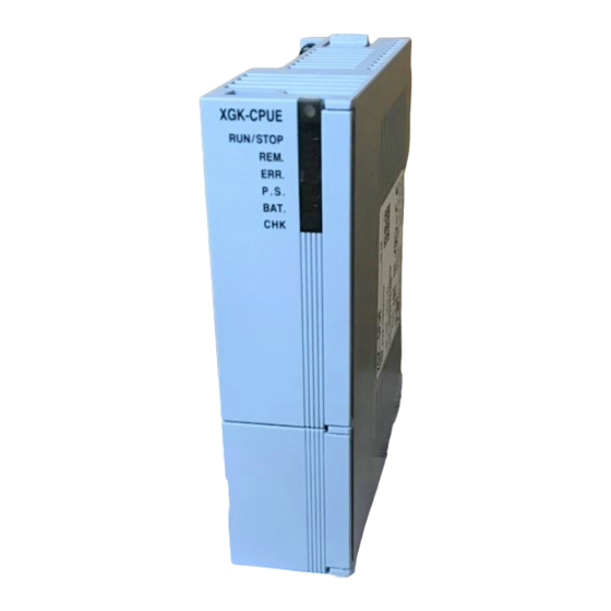
Supported functions according to CPU OS version: the following OS version and XG500 version is needed for each function. CPU OS XG5000 Function Remark V1.0 V4.0 XGK-CPUUN/CPUHN/CPUSN are added. 4.2 Part Names and Functions -a -b -c XGK-CPUH RUN/STOP -d -e... - Page 43 Chapter 4 CPU Module Names Description ON (Red): indicates that the error not possible to operate occurred. ①-c ERR LED OFF: indicates ‘no error’ ON (Red): ‘ In case that ‘user assigned flag’ is On’ ▶ ‘In case of operating in the error state by ‘operation proceeding in the ▶...
- Page 44 Chapter 4 CPU Module Names Description You can enable/disable Reset/D.Clear switch in “XG5000 Basic Parameter Basic Operation Setup” 1. When Reset switch is enabled Operation Result move to left return to center Reset move to left keep 3 seconds or Overall reset above ...
- Page 45 Chapter 4 CPU Module The name of each part about XGK-CPUUN/CPUHN/CPUSN is as followings. -a -b XGK-CPUUN -c RUN/STOP -d -e -f -a REMOTE M.XCHG -b RUN STOP RST D.CLR LINK TX/RX 10/100 BASE-TX Name Description Shows the operation status of the CPU module.
- Page 46 Chapter 4 CPU Module Name Description On(red): displaying an error of operation disabled ① - c ERR LED Off: displaying normal operation On(red): ▶ If ‘User Defined Flag’ is ‘On’ ▶ Operation in erroneous status by ‘Operation in Error Status’ PS LED setting ①...
-
Page 47: Battery
Chapter 4 CPU Module Name Description You can enable/disable Reset/D.Clear switch in “XG5000 Basic Parameter Basic Operation Setup” 1. When Reset switch is enabled Operation Result move to left return to center Reset move to left keep 3 seconds or Overall reset above ... -
Page 48: Changing The Battery
Chapter 4 CPU Module Notes In general, the battery warning occurs 5 years after purchasing but it may occur earlier due to a poor battery or excessive current discharge caused by leakage current etc. If the warning occurs again within the short time after battery change, you need to request A/S service for CPU module. -
Page 49: Chapter 5 Program Configuration And Operation Method
Chapter 5 Program Configuration and Operation Method Chapter 5 Program Configuration and Operation Method 5.1 Program Instruction 5.1.1 Program Execution Methods 1) Cyclic operation method (Scan) This is a basic program proceeding method of PLC that performs the operation repeatedly for the prepared program from the beginning to the last step, which is called ‘program scan’. -
Page 50: Operation Processing During Momentary Power Failure
Chapter 5 Program Configuration and Operation Method 2) Interrupt Operation (Time-driven, Internal Device) This is the method that stops the program operation in proceeding temporarily and carries out the operation processing which corresponds to interrupt program immediately in case that there occurs the status to process emergently during PLC program execution. -
Page 51: Scan Time
Chapter 5 Program Configuration and Operation Method 5.1.3 Scan Time The time required to complete it from the first step 0 to the next step 0 of a program, that is, a time taken for a control operation is called ‘scan time.’ It is directly related to the control performance of the system. 1) Operation and performance of XGK Program execution time, I/O data process time and communication service time are important factors affecting the ‘scan time.’... - Page 52 Chapter 5 Program Configuration and Operation Method ④ Network Service = Service of communication module in basic base+ Service of communication module in expansion base = (No. of Service x 3 ㎲) + (total TRX data(byte)/4 x 0.056 [CPUS:0.112] ㎲) + (Comm.
-
Page 53: Program Execution
Chapter 5 Program Configuration and Operation Method 5.2 Program Execution 5.2.1 Program Configuration The program is consisted of all function factors required to execute the specific control and saved in the built-in RM or flash memory of CPU module. These function factors are generally classified as follows. Function factor Process description •... - Page 54 Chapter 5 Program Configuration and Operation Method 1) Scan Program (1) Function • This program performs the operation repeatedly from 0 step to last step in order prepared by the program to process the signal that is repeatedly regularly every scan. •...
-
Page 55: Interrupt
Chapter 5 Program Configuration and Operation Method 5.2.3 Interrupt For your understanding of Interrupt function, here describes program setting method of XG5000 which is an XGT programming S/W. (For further information of XG5000, please refer to XG5000 user’s manual) Scan Program Interrupt 1 Interrupt 1 occur (Program 1) - Page 56 Chapter 5 Program Configuration and Operation Method 1) How to Prepare Interrupt Program Generate the task in the project window of XG5000 as below and add the program to be performed by each task. For further information, please refer to XG5000 user’s manual. 2) Task Type Task type and function is as follows.
- Page 57 Chapter 5 Program Configuration and Operation Method (2) Execution priority In case that several tasks to be executed are waiting, execute from the highest Task Program in priority. When the same priority tasks are waiting, execute from the order occurred. ...
- Page 58 Chapter 5 Program Configuration and Operation Method (3) Notice in using Time-driven Task Program When Time-driven task program is in execution currently or waiting for execution, if the demand to execute the same task program occurs, the new occurred task shall be disregarded. ...
- Page 59 Chapter 5 Program Configuration and Operation Method 7) Verification of Task Program Verify the following contents after writing the Task Program. (1) Is the task setting proper ? If task occurs frequently more than needed or several tasks occur in one scan at the same time, scan time may lengthen or be irregular.
- Page 60 Chapter 5 Program Configuration and Operation Method Process per time Time (ms) Process Scan started and scan program P0 started to execute 0~10 Program P0 executed 10~12 P1 execution demand, P0 stopped and P1 executed P2 execution demand 12~20 P1 execution completed and continues the stopped P0 20~22 P1 execution demand, P0 stopped and P1 executed...
-
Page 61: Operation Mode
Chapter 5 Program Configuration and Operation Method 5.3 Operation Mode For operation mode of CPU module, there are 3 types such as RUN mode, STOP mode and DEBUG mode.. Here describes the operation processing of each operation mode. 5.3.1 RUN Mode This is the mode to execute Program operation normally. -
Page 62: Stop Mode
Chapter 5 Program Configuration and Operation Method 5.3.2 STOP Mode This is the mode in stop state without Program operation. It is available to transmit the program through XG5000 only in Remote STOP mode. 1) Processing at Mode Change Clear the output image area and execute output refresh. 2) Operation Processing Contents (1) Executes I/O refresh. -
Page 63: Changing Operation Mode
Chapter 5 Program Configuration and Operation Method 5.3.4 Changing Operation Mode 1) Operation Mode Change Method The method to change operation mode are as follows. (1) By mode key of CPU module (2) By connecting the programming tool (XG5000) to communication port of CPU (3) By changing the operation mode of other CPU module connected to network by XG5000 connected to communication port of CPU (4) By using XG5000, HMI, computer link module connected to network... -
Page 64: Memory
Chapter 5 Program Configuration and Operation Method 5.4 Memory There are two types of memory in CPU module that the user can use. One is Program Memory that saves the user program written by the user to build the system, and the other is Data Memory that provides the device area to save the data during operation. -
Page 65: Data Memory
The following devices are limited to the area according to CPU type. 구 분 P*** M*** K*** F*** T*** C*** S*** XGK-CPUE XGK-CPUS XGK-CPUA P2047F M2047F K2047F F2047F T2047 C2047 S127.99 XGK-CPUH XGK-CPUU XGK-CPUSN XGK-CPUHN P4095F M4095F K4095F F4095F T8191 C4095 S255.99 XGK-CPUUN 5 - 17... - Page 66 The following devices are limited to the area according to CPU type. 구 분 D*** U*** Z*** T*** C*** XGK-CPUE U1F.31 D19999 XGK-CPUS U3F.31 XGK-CPUA U3F.31 Z127 T2047 C2047 XGK-CPUH D32767 U7F.31 XGK-CPUU XGK-CPUSN D262143 U3F.31 XGK-CPUHN Z255 T8191 C4095 D524287 U7F.31 XGK-CPUUN 5 - 18...
-
Page 67: Configuration Diagram Of Data Memory
Chapter 5 Program Configuration and Operation Method 5.5 Configuration Diagram of Data Memory 5.5.1 XGK-CPUE Bit Data area Word Data area User Program area 0000 FFFF D00000 P0000 I/O Relay Data Register Parameter area (32768 points) (20000 word) P2047 “P” M0000 D19999 “D”... -
Page 68: Xgk-Cpus
Chapter 5 Program Configuration and Operation Method 5.5.2 XGK-CPUS Bit Data area Word Data area User Program area 0000 FFFF P0000 D00000 I/O Relay Data Register Parameter area (32768 points) (20000 word) P2047 “P” M0000 User Program area D19999 “D” Auxiliary Relay (32K step) R00000... -
Page 69: Xgk-Cpua
Chapter 5 Program Configuration and Operation Method 5.5.3 XGK-CPUA Bit Data area Word Data area User Program area 0000 FFFF P0000 D00000 I/O Relay Data Register Parameter area (32768 points) (32768 word) P2047 “P” M0000 User Program area D32767 “D” Auxiliary Relay (32K step) R00000... -
Page 70: Xgk-Cpuh
Chapter 5 Program Configuration and Operation Method 5.5.4 XGK-CPUH Bit Data area Word Data area User Program area 0000 FFFF D00000 P0000 I/O Relay Parameter area Data Register (32768 points) P2047 “P” (32768 words) M0000 User Program area D32767 “D” Auxiliary Relay (64K step) R00000... -
Page 71: Xgk-Cpuu
Chapter 5 Program Configuration and Operation Method 5.5.5 XGK-CPUU Bit Data area Word Data area User Program area 0000 FFFF P0000 D00000 I/O Relay Data Register Parameter area (32768 points) P2047 “P” (32768 words) M0000 D19999 “D” User Program area Auxiliary Relay R00000 File Register... - Page 72 Chapter 5 Program Configuration and Operation Method 5.5.6 XGK-CPUSN Bit Data area Word Data area User Program area 0000 FFFF D00000 P0000 I/O Relay Data Register Parameter area (65536 points) P4095 “P” (262143 words) M0000 D19999 “D” User Program area Auxiliary Relay R00000 File Register...
- Page 73 Chapter 5 Program Configuration and Operation Method 5.5.6 XGK-CPUHN Bit Data area Word Data area User Program area 0000 FFFF D00000 P0000 I/O Relay Data Register Parameter area (65536 points) P4095 “P” (524287 words) M0000 D524287 “D” User Program area Auxiliary Relay R00000 File Register...
- Page 74 Chapter 5 Program Configuration and Operation Method 5.5.6 XGK-CPUUN Bit Data area Word Data area User Program area 0000 FFFF D00000 P0000 I/O Relay Data Register Parameter area (65536 points) P4095 “P” (524287 words) M0000 D524287 “D” User Program area...
-
Page 75: Data Latch Area Settings
Chapter 5 Program Configuration and Operation Method 5.5.9 Data Latch Area Setting When PLC stops and restarts the data required for operation or the data occurred during operation, if you want to keep and use those data, data latch can be used and it is available to use a certain area of some data device as latch area by parameter setting. - Page 76 Chapter 5 Program Configuration and Operation Method 4) Data Latch Area Operation The method to delete the latched data is as below. - D.CLR switch operation of CPU module - latch 1, latch 2 clear operation by XG5000 - write by Program (initialization program recommended) - write ‘0’...
-
Page 77: Chapter 6 Functions Of Cpu Module
Chapter 6 Function of CPU Module Chapter 6 Functions of CPU Module 6.1 Self-diagnosis (1) Self-diagnosis function means the function that CPU module diagnoses the error of PLC system itself. (2) If the power of PLC system is applied or the error occurs during operation, it detects the error and prevents the abnormal operation. -
Page 78: I/O Module Check Function
Chapter 6 Function of CPU Module 6.1.2 I/O Module Check Function This function is to check the error state of I/O module at the time of start or during operation. 1) In case that the module different from parameter setting is built-in at the time of start or it occurs the error 2) In case I/O module is removed or occurs the error during operation, the error state is detected and warning lamp (ERR) in front of CPU module and then CPU stops to operate. - Page 79 Chapter 6 Function of CPU Module (1) PLC hardware error In case of heavy error that the normal operation of PLC such as CPU module, power module is disabled, the system ‘stop’s and in case of light error such as battery error, it continues to operate. (2) Error in system configuration This error occurs when hardware configuration of PLC is different from the configuration identified in software, and the system stops.
-
Page 80: Clock
Chapter 6 Function of CPU Module 6.2 Clock CPU module has a built-in clock device (RTC). RTC continues the clock action by battery backup even in case of power off or instantaneous interruption. It is available to perform the time management such as operation history or failure history of system by using a clock data of RTC. - Page 81 Chapter 6 Function of CPU Module 3) RTC Data Modification by Program It is available for the user to set the RTC value by program. This function is used when setting the time manually through external Digit switch or making the system that corrects the time periodically through network.
-
Page 82: Remote Function
Chapter 6 Function of CPU Module 6.3 Remote Function CPU module enables to change the operation by communication except key switch mounted in the module. If you want to operate it by Remote, you should set ‘REM enable’ switch (4-pin deep) of CPU module as ‘ON’ position and ‘RUN/STOP’... - Page 83 Chapter 6 Function of CPU Module (2) Flash memory operation mode setting Online Set Flash Memory Check the ‘Enable flash memory operation mode’ Click OK Notes 1) Initial mode is Disable flash memory run mode 2) Set Enable flash memory run mode at once, it keeps the mode On until the PADT is Off 3) Change of the flash memory operation mode is available regardless of RUN/STOP Mode 4) Make sure that the program write to the flash memory completely when you try ‘modification during run’...
- Page 84 Chapter 6 Function of CPU Module (3) Flash memory operation method If you want to change the restart or operation mode the PLC system to RUN, depending on the setting of the flash operation mode, it works as follows. Set of flash memory operation mode Operation contents Or different contents of the flash memory and program memory, if the contents of the reasons the program memory such as a...
-
Page 85: Forced I/O On/Off Function
Chapter 6 Function of CPU Module 6.4 Forced I/O On/Off Function Forced I/O function is used to force I/O area ON/OFF regardless of the result of program execution. 6.4.1 Forced I/O Setup Method Click ‘Forced I/O setup’ in online mode. To set Forced I/O, select the proper flag and data check box of P device. -
Page 86: Forced On/Off Execution Point And Execution Method
Chapter 6 Function of CPU Module 6.4.2 Forced On/Off Execution Point and Execution Method (1) Forced Input Input replaces the data of contact point set as forced On/Off from the data read in input module at the time of input refresh with the forced setting data and updates the input image area. Therefore, the user program operates with actual input data while the forced setting area operates with forced setting data. -
Page 87: Saving Operation History
Chapter 6 Function of CPU Module 6.6 Saving Operation History For operation history, there are 4 types such as error history, mode conversion history, power shutdown history and system history. The time, numbers and operation contents that each event occurred, are saved in the memory and is monitored conveniently through XG5000. - Page 88 Chapter 6 Function of CPU Module Notes 1) The saved information will not be deleted before selecting the menu from XG5000 to delete. 2) If the index number saved is over 100, select Read All to check previous history. 6 - 12...
-
Page 89: External Device Error Diagnosis
Chapter 6 Function of CPU Module 6.7 External Device Error Diagnosis This is the flag provided so that the user can detect the error of external device and realize the stop and warning of system easily. By using this flag, it enables to indicate the error of external device without preparing the complicated program and monitor the error position without special device (XG5000) or source program. - Page 90 Chapter 6 Function of CPU Module Example If P10003 is on, inputs ‘100’ at ‘_ANC_WAR’ and sets system flag ‘_CHK_ANC_WAR’. And ‘_ANNUM_WAR’ is set and stops PLC. 6 - 14...
- Page 91 Chapter 6 Function of CPU Module 6.8 Fault Mask 1) Purpose and Operation Overview • Fault Mask is the function to continue the program execution even if the module error occurs during operation. The module assigned as Fault Mask shall be operated normally before error occurs. •...
-
Page 92: I/O Module Skip
Chapter 6 Function of CPU Module 6.9 I/O Module Skip 1) Purpose and Operation Overview This is the function to exclude the module assigned during operation, from operation. For the assigned module, it is disabled to update I/O data or diagnose the error from the assigned moment. It is allowed to use only in case of temporary operation excluding the error part. -
Page 93: Changing Module During Operation
Chapter 6 Function of CPU Module 6.10 Changing Module during Operation XGK system enables to change the module during operation. But, as the change of module during operation may occur the abnormal operation of whole system, special attention should be taken. Just follow the procedure assigned in this user’s manual. -
Page 94: I/O No. Allocation Method
Chapter 6 Function of CPU Module 6.11 I/O No. Allocation Method The allocation of I/O No. is to give the address to the I/O terminal of each module in order to read the data from input module and print the data to output module when performing the operation. For I/O No. -
Page 95: Module Reservation Function
Chapter 6 Function of CPU Module 6.11.3 Module Reservation Function This function is used for the variable I/O number allocation method to reserve modules to be mounted. If this function is used, the program modification is not necessary to change the I/O number. It can be set in the I/O Parameters window of XG5000. - Page 96 Chapter 6 Function of CPU Module 6.13 Local Ethernet function(XGK-CPUUN/CPUHN/CPUSN) XGK-CPUUN/CPUHN/CPUSN can carry out the functions of Ethernet server using internal local Ethernet function without extra Enet I/F module.(Note, The internal local Ethernet doesn’t offer remote connections. Only used for local connection.) 6.13.1 Local Ethernet Parameter Settings.
- Page 97 Chapter 6 Function of CPU Module (1) TCP/IP Setting Classification Description IP address Specify the IP Address of the applicable CPU module. * Note : There can be a communications disruption if you set more than 2 servers as a same IP Value necessary to check if destination station is on the same network of the Subnet mask applicable station.
- Page 98 Chapter 6 Function of CPU Module 6.13.2 Local Ethernet connection with XG5000 After finishing Local Ethernet Parameter settings, download the settings to the CPU, then user can connect to XG5000. Select Online Settings and set the options as shown below figure. Click the setting button to specify Ethernet IP.
- Page 99 Chapter 6 Function of CPU Module 6.13.3 Local Ethernet connection with XGT Server. Set the Local Ethernet Parameters as shown below figure. User can use it as a XGT Server (LSIS dedicated Protocol Communication). 6.13.4 Local Ethernet connection with TCP/IP Server. Set the Local Ethernet Parameters as shown below figure.
- Page 100 Chapter 6 Function of CPU Module Below figure is about Modbus settings. . Note 1) Modbus TCP/IP server connection function allows RST packet transmission depending on the network condition.(TCP/IP protocol) So the user devices connecting to CPU module should have RST packet process. 2) Connection to user devices can be disconnected for retransmission time-out.
-
Page 101: Chapter 7 I/O Module
Chapter 9. I/O Module Chapter 9. I/O Module 9.1 Cautions for Selecting Module It describes the cautions when selecting digital I/O modules used for the XGI series. 1) There are two digital input types; current sink input and current source input Since the wiring method of external input power varies in a DC input module, it should be selected considering the specifications of input connectors. - Page 102 Chapter 9. I/O Module 7) The following figure shows the relay life of relay output module. It also shows the max. life of relay used for relay output. AC 125V resistance load DC 30V resistance load AC 250V resistance load Current(A) 8) A clamped terminal with sleeve can not be used for the XGI terminal strip.
-
Page 103: Digital Input Module Specifications
Chapter 9. I/O Module 9.2 Digital Input Module Specifications 9.2.1 8 point DC24V input module (source/sink type) Module type DC Input module Spec. XGI-D21A Input point 8 points Insulation method Photo coupler insulation Rated input voltage DC24V Approx. 4 ㎃ Rated input current Voltage range DC20.4~28.8V (5% and lower ripple rate ) -
Page 104: Point Dc24V Input Module (Source/Sink Type)
Chapter 9. I/O Module 9.2.2 16 point DC24V input module (source/sink type) Module type DC Input module Spec. XGI-D22A Input point 16 points Insulation method Photo coupler insulation Rated input voltage DC24V Approx. 4 ㎃ Rated input current Voltage range DC20.4~28.8V (5% and lower ripple rate ) Input derating None... -
Page 105: Point Dc24V Input Module (Source Type)
Chapter 9. I/O Module 9.2.3 16 point DC24V input module (source type) Module type DC Input module Spec. XGI-D22B Input point 16 points Insulation method Photo coupler insulation Rated input voltage DC24V Approx. 4 ㎃ Rated input current Voltage range DC20.4~28.8V (5% and lower ripple rate ) Input derating None... -
Page 106: Point Dc24V Input Module (Source/Sink Type)
Chapter 9. I/O Module 9.2.4 32 point DC24V input module (source/sink type) Module type DC Input module Spec. XGI-D24A Input point 32 points Insulation method Photo coupler insulation Rated input voltage DC24V Approx. 4 ㎃ Rated input current Voltage range DC20.4~28.8V (5% and lower ripple rate ) Input derating Refer to the below derating level... -
Page 107: Point Dc24V Input Module (Source Type)
Chapter 9. I/O Module 9.2.5 32 point DC24V input module (source type) Module type DC Input module Spec. XGI-D24B Input point 32 points Insulation method Photo coupler insulation Rated input voltage DC24V Approx. 4 ㎃ Rated input current Voltage range DC20.4~28.8V (5% and lower ripple rate ) Input derating Refer to the below derating level... -
Page 108: Point Dc24V Input Module (Source/Sink Type)
Chapter 9. I/O Module 9.2.6 64 point DC24V input module (source/sink type) Module type DC Input module Spec. XGI-D28A Input point 64 points Insulation method Photo coupler insulation Rated input voltage DC24V Approx. 4 ㎃ Rated input current Voltage range DC20.4~28.8V (5% and lower ripple rate ) Input derating Refer to the below derating level... -
Page 109: Point Dc24V Input Module (Source Type)
Chapter 9. I/O Module 9.2.7 64 point DC24V input module (source type) Module type DC Input module Spec. XGI-D28B Input point 64 points Insulation method Photo coupler insulation Rated input voltage DC24V Approx. 4 ㎃ Rated input current Voltage range DC20.4~28.8V (5% and lower ripple rate ) Input derating Refer to the below derating level... -
Page 110: Point Ac110V Input Module
Chapter 9. I/O Module 9.2.8 16 point AC110V input module Module type AC Input module Spec. XGI-A12A Input point 16 points Insulation method Photo coupler insulation AC100-120V(+10/-15%) 50/60 ㎐(±3 ㎐) (5% and lower distortion) Rated input voltage Approx. 8 ㎃ (AC100,60 ㎐) , approx. 7 ㎃ (AC100,50 ㎐) Rated input current Max. -
Page 111: Point Ac220V Input Module
Chapter 9. I/O Module 9.2.9 8 point AC220V input module Module type AC input module Spec. XGI-A21A Input point 8 points Insulation method Photo coupler insulation AC100-240V(+10/-15%) 50/60 ㎐(±3 ㎐) (5% and lower distortion) Rated input voltage Approx. 17 ㎃ (AC200,60 ㎐) , approx. 14 ㎃ (AC200,50 ㎐) Rated input current Max. -
Page 112: Point Ac220V Isolated Input Module
Chapter 9. I/O Module 9.2.10 8 point AC220V isolated input module Module type AC input module Spec. XGI-A21C Input point 8 points Insulation method Photo coupler insulation AC100-240V(+10/-15%) 50/60 ㎐(±3 ㎐) (5% and lower distortion) Rated input voltage Approx. 17 ㎃ (AC200,60 ㎐) , approx. 14 ㎃ (AC200,50 ㎐) Rated input current Max. -
Page 113: Point Relay Output Module
Chapter 9. I/O Module 9.3 Digital Output Module Spec. 9.3.1 8 point relay output module Module type Relay output module Spec. XGQ-RY1A Output point 8 points Insulation method Relay insulation Rated load voltage/current DC24V 2A(resistance load) / AC220V 2A(COSΨ = 1) Min. -
Page 114: Point Relay Output Module (Surge Absorber Built-In Type)
Chapter 9. I/O Module 9.3.2 16 point relay output module Module type Relay output module Spec. XGQ-RY2A Output point 16 points Insulation method Relay insulation Rated load voltage/current DC24V 2A(resistance load) / AC220V 2A(COSΨ = 1) Min. load voltage / current DC5V / 1mA Max. - Page 115 Chapter 9. I/O Module 9.3.3 16 point relay output module (Surge Killer built-in type) Module Relay output module type XGQ-RY2B Spec. Output point 16 points Insulation method Relay insulation Rated load voltage/current DC24V 2A(resistance load) / AC220V 2A(COSΨ = 1) Min.
-
Page 116: Point Triac Output Module
Chapter 9. I/O Module 9.3.4 16 point Triac output module Module type Triac output module Spec. XGQ-SS2A Output point 16 points Insulation method Photo coupler insulation Rated load voltage AC 100-240V (50 / 60 Hz) Max. load voltage AC 264V Max. -
Page 117: Point Transistor Output Module(Sink Type)
Chapter 9. I/O Module 9.3.5 16 point transistor output module (sink type) Module type Transistor output module Spec. XGQ-TR2A Output point 16 points Insulation method Photo coupler insulation Rated load voltage DC 12 / 24V Operating load voltage range DC 10.2 ~ 26.4V Max. -
Page 118: Point Transistor Output Module(Sink Type)
Chapter 9. I/O Module 9.3.6 32 point transistor output module(sink type) Module type Transistor output module Spec. XGQ-TR4A Output point 32 point Insulation method Photo coupler insulation Rated load voltage DC 12 / 24V Operating load voltage range DC 10.2 ~ 26.4V Max. -
Page 119: Point Transistor Output Module(Sink Type)
Chapter 9. I/O Module 9.3.7 64 point transistor output module (sink type) Module type Transistor output module Spec. XGQ-TR8A Output point 64 points Insulation system Photo coupler insulation Rated load voltage DC 12 / 24V Operating load voltage range DC 10.2 ~ 26.4V Max. -
Page 120: Point Transistor Output Module(Source Type)
Chapter 9. I/O Module 9.3.8 16 point transistor output module (source type) Module type Transistor output module Spec. XGQ-TR2B Output point 16 points Insulation method Photo coupler insulation Rated load voltage DC 12 / 24V Operating load voltage range DC 10.2 ~ 26.4V Max. -
Page 121: Point Transistor Output Module(Source Type)
Chapter 9. I/O Module 9.3.9 32 point transistor output module (source type) Module type Transistor output module Spec. XGQ-TR4B Output point 32 points Insulation method Photo coupler insulation Rated load voltage DC 12 / 24V Operating load voltage range DC 10.2 ~ 26.4V Max. -
Page 122: Point Transistor Output Module(Source Type)
Chapter 9. I/O Module 9.3.10 64 point transistor output module (source type) Module type Transistor output module Spec. XGQ-TR8B Output point 64 points Insulation method Photo coupler insulation Rated load voltage DC 12 / 24V Operating load voltage range DC 10.2 ~ 26.4V Max. -
Page 123: Point Transistor Isolated Output Module
Chapter 9. I/O Module 9.3.11 8 point transistor isolated output module Module type Transistor output module Spec. XGQ-TR1C Output point 8 points Insulation method Photo coupler insulation Rated load voltage DC 12 / 24V Operating load voltage range DC 10.2 ~ 26.4V Max. -
Page 124: Digital Io Module
Chapter 9. I/O Module 9.4 Digital I/O Module Specifications 9.4.1 32 point (DC input · transistor output) I/O combined module XGH-DT4A Input Output Input point 16 points Output point 16 points Insulation method Photo coupler insulation Insulation method Photo coupler insulation Rated input voltage DC 24V Rated load voltage... -
Page 125: Event Input Module
Chapter 9. I/O Module 9.5 Event Input Module 9.5.1 Event Input Module (Source/Sink type) Specification XGF-SOEA Input point 32 point Insulation method Photo coupler insulation Memory size Records 1Mbit event information (300 event information per XGF-SOEA module) Precision 1 ms (±2ms : error between modules) Rated input voltage DC24V Rated input current... -
Page 126: Smart Link
Chapter 9. I/O Module 9.6 Smart Link 9.6.1 Modules accessible to Smart Link From digital I/O modules used for XGT Series, the modules accessible to Smart Link are as follows. 32 point modules need a Connector(40 Pin x 1), 64 point modules need 2 connectors(40 Pin x 2) Model Specification No. -
Page 127: Smart Link Mapping Table
Chapter 9. I/O Module 9.6.3 Smart Link Mapping Table ❶ ❷ : Module using 1ea Cable : Module using 2ea Cable 9.6.4 Smart Link Connection Cable Smart Link 9-27... -
Page 128: Smart Link Connection Diagram
Chapter 9. I/O Module 9.6.5 Smart Link Connection Diagram (1) XGI-D24A/B 1) Applicable Smart Link Model Cable Length of Cable C40HF-05PB-1B 0.5m C40HF-10PB-1B TG7-1H40S C40HF-15PB-1B 1.5m C40HF-20PB-1B C40HF-30PB-1B Terminal board 0.5m C40HF-05PB-1B C40HF-10PB-1B TG7-1H40CA C40HF-15PB-1B 1.5m (Common120Pin1Added) C40HF-20PB-1B C40HF-30PB-1B 2) Connection Diagram (XGI-D24A/B) (a) TG7-1H40S 9-28... - Page 129 Chapter 9. I/O Module (b) TG7-1H40CA Common Contacts set1 Common Contacts set2 9-29...
- Page 130 Chapter 9. I/O Module (2) XGI-D28A/B 1) Applicable Smart Link Model Cable Length of Cable C40HF-05PB-1B 0.5m C40HF-10PB-1B TG7-1H40S C40HF-15PB-1B 1.5m C40HF-20PB-1B C40HF-30PB-1B Terminal board C40HF-05PB-1B 0.5m C40HF-10PB-1B TG7-1H40CA C40HF-15PB-1B 1.5m (Common120Pin1Added) C40HF-20PB-1B C40HF-30PB-1B 2) Connection Diagram (XGI-D28A/B) (a) TG7-1H40S 9-30...
- Page 131 Chapter 9. I/O Module (b) TG7-1H40CA Common Contacts set1 Common Contacts set2 9-31...
- Page 132 Chapter 9. I/O Module (3) XGQ-TR4A/8A 1) Applicable Smart Link Model Cable Length of Cable C40HF-05PB-1B 0.5m C40HF-10PB-1B TG7-1H40S C40HF-15PB-1B 1.5m C40HF-20PB-1B C40HF-30PB-1B Terminal board C40HF-05PB-1B 0.5m C40HF-10PB-1B TG7-1H40CA C40HF-15PB-1B 1.5m (Common120Pin1Added ) C40HF-20PB-1B C40HF-30PB-1B C40HF-05PB-1 0.5m C40HF-10PB-1 Relay R32C-NS5A-40P C40HF-15PB-1 1.5m board...
- Page 133 Chapter 9. I/O Module (b) TG7-1H40CA Common Contacts set1 Common Contacts set2 (c) R32C-NS5A-40P 9-33...
- Page 134 Chapter 9. I/O Module (4) XGQ-TR4B/8B 1) Applicable Smart Link Model Cable Length of Cable 0.5m C40HF-05PB-1B C40HF-10PB-1B TG7-1H40S C40HF-15PB-1B 1.5m C40HF-20PB-1B C40HF-30PB-1B Terminal board C40HF-05PB-1B 0.5m C40HF-10PB-1B TG7-1H40CA C40HF-15PB-1B 1.5m (Common120Pin1Added ) C40HF-20PB-1B C40HF-30PB-1B C40HF-05PB-XGP1 0.5m C40HF-10PB-XGP1 Relay R32C-PS5A-40P C40HF-20PB-XGP1 board (Source type)
- Page 135 Chapter 9. I/O Module (b) TG7-1H40CA Common Contacts set1 Common Contacts set2 (c) R32C-PS5A-40P 9-35...
- Page 136 Chapter 9. I/O Module (5) XGF-SOEA 1) Applicable Smart Link Model Cable Length of Cable C40HF-05PB-1B 0.5m C40HF-10PB-1B TG7-1H40S C40HF-15PB-1B 1.5m C40HF-20PB-1B C40HF-30PB-1B Terminal board 0.5m C40HF-05PB-1B C40HF-10PB-1B TG7-1H40CA C40HF-15PB-1B 1.5m (Common120Pin1Added ) C40HF-20PB-1B C40HF-30PB-1B 2) Connection Diagram (XGF-SOEA) (a) TG7-1H40S 9-36...
- Page 137 Chapter 9. I/O Module (b) TG7-1H40CA Common Contacts set1 Common Contacts set2 9-37...
-
Page 138: Smart Link Specifications & Dimensions
Chapter 9. I/O Module 9.6.6 Smart Link Specifications & Dimensions (1) TG7-1H40S 1) Specifications Rated Voltage AC, DC 125V Rated Current Withstanding Voltage 600V 1min 100MΩ (DC 500V) Insulation resistance 1.25 ㎟ /MAX Applicable Wire T/B Screw M3 X 10L Screw Torque 1.2N •... - Page 139 Chapter 9. I/O Module (2) TG7-1H40CA 1) Specifications Rated Voltage 125V AC / 24V DC Rated Current Common 10A (Total) 100MΩ (DC 500V) Insulation resistance Withstanding Voltage AC500V 1min AWG22-16 (MAX / 1.5 ㎟) Applicable Wire Contact Screw M3 X 10L Screw Torque 1.2N •...
- Page 140 Chapter 9. I/O Module (3) R32C-N(P)S5A-40P 1) Specifications (a) Relay Board Case Modified PPO Protective Cover Polycarbonate Epoxy 1.6t / 2oz AWG22-16 (MAX / 1.5 ㎟) Applicable Wire T/B Screw M3 X 8L Screw Torque 1.2N • m(12Kgf • cm) -10℃...
-
Page 141: Chapter 8 Power Module
Chapter 8 Power Module Chapter 8 Power Module Here describes the selection method, type and specification of power module. 8.1 Selection Method The selection of power module is determined by the current that voltage and power module of input power supply to the system, that is, the sum of current consumption of digital I/O module, special module and communication module which are installed on the same base as power module. - Page 142 Chapter 8 Power Module COM. COM. OUT Power AC power 100V~240V Constant voltage transformer DC24 Load AC power 100V~240V power...
-
Page 143: Specifications
Chapter 8 Power Module 8.2 Specifications Items XGP-ACF1 XGP-ACF2 XGP-AC23 XGP-DC42 Rated input voltage AC110V/220V AC220V DC24V Input voltage range AC85V ~ AC264V AC170V ~ AC264V Input frequency 50 / 60 Hz (47 ~ 63 Hz) Inrush current or less or less Peak Peak... -
Page 144: Part Names
Chapter 8 Power Module 8.3 Part Names Here describes the names of each part and its purpose of power module. ① ② ③ ④ ⑤ ⑥ ⑦ Names Purpose Power LED DC5V power indication LED Power supply to the module required for DC24V in output module. DC24V, 24G terminal ▶XGP-ACF2, XGP-ACF3 does not print out DC24V. -
Page 145: Current Consumption/Power Calculation Example
Chapter 8 Power Module 8.4 Current Consumption/Power Calculation Example Here describes which power module should be used in case of XGK system that the following module is mounted. Voltage system Type Model Number of setup CPU module XGK-CPUH 0.96A 12 Slot main base XGB-B12M Input module XGI-D24A... -
Page 146: Chapter 9 Base And Extended Cable
Chapter 9 Base and Extended Cable Chapter 9 Base and Extended Cable 9.1 Specification 9.1.1 Main Base Main base installs Power Module, CPU Module, I/O Module and Special Communication Module. Model XGB-M12A XGB-M08A XGB-M06A XGB-M04A Items I/O module setup 12 module 8 module 6 module 4 module... -
Page 147: Main Base
Chapter 9 Base and Extended Cable 9.2 Part Names 9.2.1 Main Base Base attached guide hole Power module connector Module built-in connector Hole to attach the main base I/O module built-in I/O module built-in connector to the panel in control panel connecto PE terminal Extended cable connector... -
Page 148: Chapter 10 Built-In Pid Functions
Chapter 10 Built-in PID Functions Chapter 10 Built-in PID Functions This chapter describes the XGK Series CPU built-in PID function. Sections 10.2 and 10.3 cover the principles and structure of PID control; the subsequent sections are dedicated to the PID function built into XGK Series. 10.1 Features The features of the PID function built into XGK Series (XGK-CPUH, XGK-CPUA, XGK-CPUS, XGK-CPUE, XGK-CPUU) are as follows. -
Page 149: Terms
Chapter 10 Built-in PID Functions 10.3 PID Control Operation 10.3.1 Terms Below are the terms used to describe the PID control operation. : The target state the control object should reach T_s (Ts) : Sampling time (Control cycle) K_p (Kp) : Proportional coefficient T_i (Ti) : Integral time constant... -
Page 150: P Control
Chapter 10 Built-in PID Functions 10.3.3 P control As shown in the following expression (10.3.7), MV in P control is composed of the proportional term operation MV_p only. The proportional term operates in the form of the multiplication of the error by the proportional coefficient. -
Page 151: Pi Control
Chapter 10 Built-in PID Functions 10.3.4 PI control As shown in the following expression (10.3.10), PI (Proportional-Integral) control is calculated as the sum of the proportional and integral terms. To reduce the offset, the shortcoming of the proportional term, PI control uses the integrated error. -
Page 152: Pid Control
Chapter 10 Built-in PID Functions 10.3.5 PID control As shown by (10.3.1) ~ (10.3.5), PID control reduces vibration during PI control by adding the derivative effect to PI control. The derivative effect operates only when the system state changes, regardless of the system error value. -
Page 153: Pid Instructions
Chapter 10 Built-in PID Functions 10.4 PID Instructions 10.4.1 PID loop states A PID loop has 5 states: PIDSTOP, AT (Auto-tuning), PIDRUN, PIDCAS, and PIDPAUSE. (1) PIDSTOP is a state in which the output (MV) is represented by MV_min, the internal states are initialized, and user settings are maintained. -
Page 154: Pid Instruction Group
Chapter 10 Built-in PID Functions 10.4.2 PID instruction group The PID instruction group includes 5 instructions: PIDRUN, PIDCAS, PIDINIT, PIDPRMT, and PIDPAUSE. In fact, all operations of the PID function are performed by the PIDRUN or PIDCAS instruction. The three other additional instructions (PIDINIT, PIDPRMT, PIDPAUSE) operate normally when the PIDRUN or PIDCAS instruction also exists on the ladder program. - Page 155 Chapter 10 Built-in PID Functions (3) PIDINIT PIDINIT is used to initialize the settings and states of the current PID loop. All the setting values of the corresponding loop are initialized as 0 (Off in case of bit). Instruction PIDINIT Operand S has the range 0 ~ 31 (constants) and means the loop number.
-
Page 156: Pid Flag Configuration
Chapter 10 Built-in PID Functions 10.5 PID Flag Configuration The table below shows the PID flag configuration for use of the built-in PID function. KDevice Zone Symbol Data Type Content K10000+m _PIDn_MAN PID Output Select (0:Auto, 1:Manual) K10020+m _PIDn_PAUSE PID Pause (0: STOP/RUN 1:PAUSE) K10040+m _PIDn_REV PID Operation Select (0:Fwd, 1:Rev) - Page 157 Chapter 10 Built-in PID Functions The PID instruction uses part of the K device to perform operation. When the PID function is not used, the K device can be used as a general Keep Relay. The area of K0000 ~ K0999 is not used by the PID function so as to guarantee compatability with previous PLC models and secure the user’s area.
-
Page 158: Common Bit Area
Chapter 10 Built-in PID Functions 10.5.1 Common bit area The common bit area is the part that contain all bit data for the 32 loops. All information 32 loops have for a signel item is combined to take the form of 32 bit double word; the nth bit provides information on the nth loop; m is the hexadecimal value of loop number n. - Page 159 Chapter 10 Built-in PID Functions (4) _PIDn_AW2D (PID Anti Wind-up 2 Disable) - Setting Area K DEVICE AREA : K10060+m Unit : Bit If this bit is turned OFF at the user’s will, The Anti Wind-up2 function is inactivated. The Anti Wind-up function is described in detail in 10.6. If the corresponding bit is Off, [Default] Anti Wind-up2 is enabled.
- Page 160 Chapter 10 Built-in PID Functions (8) _PIDn_AT_EN (PID Auto-Tuning ENable) - Setting Area K DEVICE AREA : K10140+m Unit : Bit This performs AT (Auto-tuning) of the corresponding PID loop. The approximate T_s (operation cycle) and PID coefficients (K_p, T_i, T_d) of the systemare are determined through AT. Do not forget to set the PIDn_HYS_val item before starting AT.
-
Page 161: Individual Data Area
Chapter 10 Built-in PID Functions 10.5.2 Individual data area The individual data area is in the range of K1024 ~ K2047 and a 32 word length is assigned for each of 32 loops. So, the individual data area of the nth loop is K (1024+32n) ~ K (1055+32n). (1) _PIDn_SV (PID Set-point Value) - Setting Area K DEVICE AREA : K1024+32n... - Page 162 Chapter 10 Built-in PID Functions (4) _PIDn_T_i (PID integral Time gain) - Setting Area K DEVICE AREA : K1028+32n Unit : REAL [ -3.40282347e+38 ~ -1.17549435e-38 , 0 , 1.17549435e-38 ~ 3.40282347e+38 ] This sets the integral time constant (T_i) of the corresponding loop. As T_i divides the I (integral) term, the larger T_i, the smaller the integral effect.
- Page 163 Chapter 10 Built-in PID Functions (8) _PIDn_MV_max (PID MV MAXimum limit) - Setting Area K DEVICE AREA : K1034+32n Unit : INT [ -32768 ~ 32767 ] This limits the maximum MV value of the corresponding loop. This prevents overload and system errors by limiting the maximum value of the controller output transferred to the output equipment.
- Page 164 Chapter 10 Built-in PID Functions (12) _PIDn_PV (PID Process Variable) - Input/Output Area K DEVICE AREA : K1038+32n Unit : INT [ -32768 ~ 32767 ] This displays the PV of the corresponding loop. PV is an indicator of the current state of the system. In general, the input from the sensor is stored on the U device of the CPU via an input device such as A/D conversion module: At each scan, this value should be transferred to _PIDn_PV using a instruction such as MOV.
- Page 165 Chapter 10 Built-in PID Functions (16) _PIDn_ERR (PID ERRor value) - Setting Prohibited K DEVICE AREA : K1042+32n Unit : DINT [ -2747483648 ~ 2747483647 ] This is the current error value of the corresponding loop. An error value in PID is defined as SV – PV. This is used as an indicator of how far the current state is from the desired state.
- Page 166 Chapter 10 Built-in PID Functions (21) _PIDn_Td_lag (PID Td lag filter) - Setting Area K DEVICE AREA : K1051+32n Unit : WORD [ 0 ~ 65535 ] This sets the primary delay filter for the corresponding loop so as to allow the derivative effect acting as an instantaneous impact to act more slowly and continuously.
- Page 167 Chapter 10 Built-in PID Functions Note Transient and Normal States 1) Transien State : A state during which the control system starts its control operatoin and reaches the desired control state; there often occurs an instantaneous output variation and, while the integral value approaches stability, there may occur a vibration or overshoot.
-
Page 168: Convenient Additional Functions Of Pid Instructions
Chapter 10 Built-in PID Functions 10.6 Convenient Additional Functions of PID Instructions This section describes additional functions that can be conveniently used in combination with the PID instructions. 10.6.1 Various PID-based control methods Commonly used among PID controls are P control, PI control, PD control and PID control. When a certain feature (mostly stabilization) is required, ID control, I control or D control is often used though they are somehow more complicated. -
Page 169: Operation And Function Of Cascade (Cas)
Chapter 10 Built-in PID Functions 10.6.4 Operation and function of cascade (CAS) PDCAS performs cascade PID control through sequential operation of two PID loops. Generally, cascade PID control is used for temperature control through chemical process or fuel control; The two loops used here are called master loop and slave loop. -
Page 170: How To Use Pid Instructions
Chapter 10 Built-in PID Functions 10.7 How to Use PID Instructions This section describes how to use PID instructions. For detailed description of the functions of the CPU, specific modules and XG5000, refer to the corresponding manuals. 10.7.1 Hardware configuration The example system has a configuration as shown below. - Page 171 Chapter 10 Built-in PID Functions The following figure shows the screen of XGF-AV8A setting in XG5000. (3) Analog output Module (XGF-DV4A) The analog output module converts a controller output digital value generated through control operation in the PLC to 4mA ~ 20mA and transfers it to the driver of the control object. The XGF-DV4A model has 4 channels and its setting can be changed through the I/O parameter setting window, as in XGXGF-AV8A.
-
Page 172: Program Example 1
Chapter 10 Built-in PID Functions (5) Control Object The current system uses a water level control system as the control object. A water level control system is a stem to maintain a desired water level by pumping water into a water tank whose lower part has a small opening for outflow of water. -
Page 173: Pid Controlling
Chapter 10 Built-in PID Functions Step 1: Each channel 0 of the analog input and output modules is enabled using the regular On contact. Step 7: The analog input module input data are transferred to PIDRUN Loop 0 PV using the regular On contact. - Page 174 Chapter 10 Built-in PID Functions (2) Determination of SV In order to set SV, the PV value of the system desired by the user should be determined. To put it easily, in order to maintain the water level at 250mm, the PV value for 250mm should be determined. This value can be determined through numerical analysis of the system but it will be more exactly determined by experimenting with the reaction of the control object.
- Page 175 Chapter 10 Built-in PID Functions (4) Observation of Control States Using the Trend Monitor You can enable the trend monitor, one of the monitor functions of XG5000. The trend monitor can be properly arranged by allowing its docking. Data to be observed are registered through the trend setting. 10 - 28...
- Page 176 Chapter 10 Built-in PID Functions The monitoring cycle is set to 200m and, after the trend graph tap in the lower part is selected, SV and PV of Loop 0 are registered as INT. (5) Program Run (Here an example is given to show how to find a parameter manually. For auto tuing, refer to the method below.) When the contact (M00000) is turned On, the system starts up.
- Page 177 Chapter 10 Built-in PID Functions Because the T_i value is too large, the normal state offset lasts long and there occurs a slight overshoot. Settings are mede as follows: K_p = 10, T_i = 1. Because T_i is too small, PV fluctuates slowly. Settings are made as follows: K_p = 10, T_i = 5 This is a satisfactory result.
- Page 178 Chapter 10 Built-in PID Functions The system rocks and the error increases. Since the current system is a slow system that can be fully controlled by PI, only PI control is required. Therefore, the tuning results are as follows: K_p = 10, T_i = 5, T_d = 0 10 - 31...
-
Page 179: How To Start Up Using At (Auto-Tuning)
Chapter 10 Built-in PID Functions 10.7.4 How to start up using AT (Auto-tuning) This section explains the correct AT setting method through operating the system described in 10.7.3 using the AT function. The basic AT function properly operates when the system is not started yet or when the system has PV at least smaller (larger in case of reverse operation) than the _PIDn_AT_SV value. -
Page 180: Program Example 2
Chapter 10 Built-in PID Functions The above graph shows a water level waveform obtained by setting _PIDn_HYS_val too small (10 in the figure). If a rectangular waveform does not appear 3 times in MV, a correct AT operation cannot be guranteed. -
Page 181: Startup Using Pwm
Chapter 10 Built-in PID Functions 10.7.6 Startup using PWM Input is done using the A/D conversion module as shown in the simulation above and the output signal is converted to PWM to control the system using a relay module or TR module. The following figure shows a program example of performing PID control using A/D and D/A conversion modules. -
Page 182: Cascade Startup
Chapter 10 Built-in PID Functions 10.7.7 Cascade startup The ladder program above is a cascade startup program based on the block diagram below. User Cascade loop K1024 K1066 = K1040 (Auto) Master loop K1038 U01.02 K1070 Slave K1072 Thermometer loop (1) U00.03 U01.03 Heating... -
Page 183: Chapter 11 Installation And Wiring
Chapter 11 Installation and Wiring Chapter 11 Installation and Wiring 11.1 Installation 11.1.1 Installation Environment This equipment has a high reliability regardless the installation environment. However, cares should be taken for the following items in order to secure the reliability and stability. 1) Environment Condition (1) Install in control panel with water-proof and vibration-proof. - Page 184 Chapter 11 Installation and Wiring The following shows the method to calculate the current consumption of PLC system itself necessary for heat protection design. 4) Current Consumption Block Diagram of PLC System COM. COM. OUT Power AC power 100V~240V Constant voltage transformer DC24...
- Page 185 Chapter 11 Installation and Wiring (5) Input average current consumption of input module (current consumption of simultaneous On point) • W X E X input point X simultaneous On rate (W) : Input current (actual value in case of AC) (A) E : Input voltage (voltage in actual use) (V) (6) Current consumption of Special module power •...
-
Page 186: Handling Precautions
Chapter 11 Installation and Wiring 11.1.2 Handling Precautions Here describes the notices in handling from the opening of each module to installation. • Do not fall or apply the deep impact. • Do not remove PCB from the case. It may cause the failure. •... - Page 187 Chapter 11 Installation and Wiring (6) Terminal Block Check the compression state of terminal block and pay attention not to enter the fragments of cable into PLC in case of wiring of terminal block or processing the screw hole. If not, it may cause the abnormal operation or the failure.
- Page 188 Chapter 11 Installation and Wiring (6) Do not install PLC to the direction as below. (7) When installing PLC or other equipment (Relay, electronic contactor), keep the distance to avoid radiant noise or heat. 100mm or more 50mm or more 50mm or more 11-6...
-
Page 189: Attachment/Detachment Of Module
Chapter 11 Installation and Wiring 11.1.3 Attachment/Detachment of Module Here describes the method to attach each module to the base or remove it. 1) Attachment of Module • Insert a fixed projection of the lower part of PLC into the module fixed hole of the base. •... - Page 190 Chapter 11 Installation and Wiring 2) Detachment of Module • Loosen the fixed screws of the upper part of module from the base. • Hold the module by both hands and press the fixed hook of module thoroughly. • By pressing the hook, pull the upper part of module from the axis of the lower part of module. •...
-
Page 191: Wiring
Chapter 11 Installation and Wiring 11.2 Wiring Here describes the items to know related to the wiring, in case of using the system. 11.2.1 Power Wiring 1) In case that the power change is larger than the range of standard, connect the voltage regulated transformer. - Page 192 Chapter 11 Installation and Wiring 4) In case of using a DC24V output of Power Module Do not connect a DC24V output of several power module in parallel. If connected in parallel, the module may be broken. In case that DC24V output capacity of one power module is not enough, supply the external DC24V power as below.
-
Page 193: I/O Device Wiring
Chapter 11 Installation and Wiring 11.2.2 I/O Device Wiring 1) The spec. of cable for I/O wiring shall be 0.3~2 mm but it is recommend to use the convenient cable spec.(0.3 mm 2) Separate Input cable and Output cable for wiring. 3) I/O signal cable should be separated more than 100mm from main circuit cable of high voltage/high current. -
Page 194: Cable Specifications For Wiring
Chapter 11 Installation and Wiring 4) Use more than 2 mm cable for earth. Place the earth point near this PLC as possible to have the short length of earth cable. 5) Separate LG of power module and PE of base board for earth. A) dedicated earth : Best B) common earth : Good C) common earth: Poor... -
Page 195: Chapter 12 Maintenance And Repair
Chapter 12 Maintenance and Repair Chapter 12 Maintenance and Repair Please carry out Daily Checking and Regular Checking to maintain PLC in best condition. 12.1 Repair and Checking As I/O module is mainly consisted of semiconductor elements, the life seems to be semi-permanent. But the error in the elements may occur by surrounding environment and thus the regular checking is needed. -
Page 196: Regular Checking
Chapter 12 Maintenance and Repair 12.3 Regular Checking Check the following items 1~2 times every 6 months and take a necessary actions. Checking items Contents Judgment Basis Action 0 ~ 55 °C Temperature Adjust to meet general Thermometer/humidifier Surrounding specification Humidity corrosive gas 5 ~ 95%RH... -
Page 197: Chapter 13 Emc Directive
Chapter 13 EMC Directive Chapter 13 EMC Directive 13.1 Requirements for Conformance to EMC Directive The EMC Directive specifies the products must “be so constructed that they do not cause excessive electromagnetic interference (emissions) and are not unduly affected by electromagnetic interference (immunity)”. The applicable products are requested to meet these requirements. -
Page 198: Control Panel
Chapter 13 EMC Directive 13.1.2 Control Panel The PLC is an open type device (device installed to another device) and must be installed in a control panel. This is needed to prevent electric shock by touching XGK PLC and reduce the PLC-generated noise. Install the XGK PLC in a metallic panel to reduce PLC-generated EMI (Electro-magnetic interference), The specifications for the control panel are as follows: 1) Control panel... -
Page 199: Cables
Chapter 13 EMC Directive 2) Connection of power and earth wires Earthing and power supply wires for the PLC system must be connected as described below. (1) Earth the control panel with a thick wire so that a low impedance connection to ground can be ensured even at high frequencies. -
Page 200: Requirement To Conform To The Low-Voltage Directive
Chapter 13 EMC Directive 13.2 Requirement to Conform to the Low-voltage Directive The low-voltage directive requires each device that operates with the power supply ranging from 50V to 1000VAC and 75V to 1500VDC to satisfy the safety requirements. Cautions and installation and wiring of the PLC XGK series to conform to the low-voltage directive are described in this section. -
Page 201: Chapter 14 Troubleshooting
Chapter 14 Troubleshooting Chapter 14 Troubleshooting Here describes the contents of various errors to be occurred while operating the system, the methods to find the causes and the actions. 14.1 Basic Procedure for Troubleshooting It is important to use the high reliable machine to increase the system reliability but it is important to take a prompt action when the trouble occurs as well. -
Page 202: Action When Power Led Is Off
Chapter 14 Troubleshooting 14.2.1 Action when Power LED is OFF Here describes the action procedure when Power LED is OFF while supplying the power or during operation. Power LED is OFF Is the power Supply the power supplying ? Is Power LED ON? Meet the power supply with Is the power voltage within the regular range. -
Page 203: Action When Err Led Is Blinking
Chapter 14 Troubleshooting 14.2.2 Action when ERR LED is blinking Here describes the action procedure when ERROR LED is blinking in case of power supply, or when operation starts, or during operation. ERR LED is blinking Connect XG5000 and check the error code contents. -
Page 204: Action When Run, Stiop Led Is Off
Chapter 14 Troubleshooting 14.2.3 Action when Run, Stop LED is OFF Here describes the action procedure when RUN, STOP LED is OFF in case of power supply, when operation starts or during operation. RUN, STOP LED is OFF Power module OFF → ON Is RUN, STOP LED OFF ? Contact A/S center or agent nearest from you... -
Page 205: Action When I/O Module Does Not Work Normally
Chapter 14 Troubleshooting 14.2.4 Action when I/O Module does not work normally Here describes the action procedure when I/O Module does not work normally during operation, as shown on the program example below. When I/O module does not work normally Is output LED of SOL1 ON ? Measure SOL1 terminal... - Page 206 Chapter 14 Troubleshooting Continued Is SWITCH 1, 2 LED ON ? Measure the terminal Measure the terminal voltage of SWITCH 1, 2 voltage of SWITCH 1, 2 by the tester. by the tester. Is the Is the Is the measured tightening state of measured value value normal ?
- Page 207 Chapter 14 Troubleshooting 14.2.5 Action when PROGRAM WRITE does not work Here describes the action procedure when PROGRAM WRITE does not work in CPU Module. Program Write does not work Put the key switch to Remote Is the Run/Stop switch set as STOP mode and run Program STOP (Remote stop) mode ? Write.
-
Page 208: Questionnaire For Troubleshooting
Chapter 14 Troubleshooting 14.3 Questionnaire for Troubleshooting If the trouble occurs when using XGK series, fill in the following questionnaire and then contact customer’s service center by phone or FAX. For the error related to special and communication module, fill in the questionnaire attached to the user’s manual of the corresponding product. -
Page 209: Cases
Chapter 14 Troubleshooting 14.4 Cases Here describes the trouble type and measures for each circuit. 14.4.1 Input Circuit Error Type and Corrective Actions Here describes the trouble examples of input circuit and its measures. Phenomena Causes Measures Connect the proper resistance and Leakage current of external device Input signal (In case of running by approach switch) -
Page 210: Output Circuit Error Types And Corrective Actions
Chapter 14 Troubleshooting 14.4.2 Output Circuit Error Types and Corrective Actions Here describes the trouble examples of output circuit and its measures. Phenomena Causes Measures In case that the load is semi-sine Connect several dozens kΩ ~ Over voltage inside, (solenoid valve) hundreds kΩ... - Page 211 Chapter 14 Troubleshooting Phenomena Causes Measures Over current when Off Insert the magnetic contactor that time [In case of running the inductive load of constant is small and run the load by the Response current such as solenoid (time constant L/R contact as below.
-
Page 212: Error Code List
Chapter 14 Troubleshooting 14.5 Error Code List 14.5.1 Error Code during CPU Operation Error Action Operatio Diagnosi Error cause code (restart mode after taking an action) n status status s point Blink by If it occurs repeatedly when power the order Power Data Bus error Fail... - Page 213 Chapter 14 Troubleshooting Error Action Operatio Diagnosi Error cause code (restart mode after taking an action) n status status s point After checking the wrong position of Module set in slot by XG5000, modify the module or parameter and the Stop ERR: On parameter and then restart.
-
Page 214: Error Code Of Program Operation
Chapter 14 Troubleshooting Error Action Operatio Diagnosi Error cause code (restart mode after taking an action) n status status s point external device device (Run) (P.S.: On) detected by the Refer to flag to repeat the device and user program then restart (according to parameter) The number of While... - Page 215 Chapter 14 Troubleshooting Code Error CPU Status Causes Measure DECO/ENCO Set value is over than 8 Correct the set value error DIS/UNI error The value of N is over 4 Correct the N value Data control error Over the range Correct the range Time data error Time data error...
-
Page 216: Appendix 1 Flag List
Appendix 1 Flag List Appendix 1 Flag List App.1.1 Special Relay (F) List Device1 Device2 Type Variables Function Description Indicates PLC mode and operation F0000 DWORD _SYS_STATE Mode and state state F00000 _RUN Run state F00001 _STOP Stop Stop state F00002 _ERROR Error... - Page 217 Appendix 1 Flag List Device1 Device2 Type Variables Function Description F0002 DWORD _CNF_ER System error Reports heavy error state of system F00020 _CPU_ER CPU error CPU configuration error F00021 _IO_TYER Module Type error Module Type does not match F00022 _IO_DEER Module detachment error Module is detached.
- Page 218 Appendix 1 Flag List Device1 Device2 Type Variables Function Description F00053 _HS_WAR12 High speed link 12 High speed link - parameter 12 error F00054 _P2P_WAR1 P2P parameter 1 P2P – parameter 1 error F00055 _P2P_WAR2 P2P parameter 2 P2P – parameter 2 error F00056 _P2P_WAR3 P2P parameter 3...
- Page 219 Appendix 1 Flag List Device1 Device2 Type Variables Function Description F0011 WORD _LOGIC_RESULT Logic result Indicates logic results ON during 1 scan in case of operation F00110 _LER operation error error F00111 _ZERO Zero flag ON when operation result is 0 F00112 _CARRY Carry flag...
- Page 220 Appendix 1 Flag List Device1 Device2 Type Variables Function Description F0053 WORD _MON_YEAR Month/Year PLC month, year data F0054 WORD _TIME_DAY Time/Day PLC time, day data F0055 WORD _SEC_MIN Sec/Min PLC second, minute data Hundred F0056 WORD _HUND_WK PLC hundred year, weekday data year/Weekday F0057 WORD...
- Page 221 Appendix 1 Flag List Device1 Device2 Type Variables Function Description F0093 WORD _IO_RWER_N RW error slot Module read/write error slot no. F0094 WORD _IP_IFER_N IF error slot Module interface error slot no. F0096 WORD _IO_TYER0 Module Type 0 error Main base module Type error F0097 WORD _IO_TYER1...
- Page 222 Appendix 1 Flag List Device1 Device2 Type Variables Function Description Module Extended base 7 step module read/ F0127 WORD _IO_RWER7 error write error F0128 WORD _IO_IFER_0 Module IF 0 error Main base module interface error Extended base 1step module interface F0129 WORD _IO_IFER_1...
- Page 223 Appendix 1 Flag List Device1 Device2 Type Variables Function Description Setting in case of F09323 _CP_ER_PMT communication Ignores communication module error error F0934 DWORD _BASE_EMASK_INFO Base fault mask Base fault mask information F0936 DWORD _BASE_SKIP_INFO Base Skip Base skip information F0938 WORD _SLOT_EMASK_INFO_0...
- Page 224 Appendix 1 Flag List Device1 Device2 Type Variables Function Description F09600 _HS1_ENABLE_STATE High speed link state High speed link 1 enable/disable current state _HSx_ENABLE_STATE High speed link state High speed link x enable/disable current state F0960B _HS12_ENABLE_STATE High speed link state High speed link 12 enable/disable current state F10300 _HS1_REQ...
- Page 225 Appendix 1 Flag List Appendix 1.2 Communication Relay (L) List Here describes data link communication relay(L). [Table 1] Communication Flag List according to High speed link no.(High speed link no. 1 ~ 12) Keyword Type Contents Description Indicates normal operation of all station according to parameter set in High speed link, and ON under the condition as below.
- Page 226 Appendix 1 Flag List Notes High speed L area address Remarks link no. Comparing with High speed link 1 from [Table 1], the flag address of different L000500~L00099F high speed link station no. is as follows by a simple calculation formula. L001000~L00149F L001500~L00199F ∗...
- Page 227 Appendix 1 Flag List [Table 2] Communication Flag List according to P2P Service Setting P2P parameter: 1~8, P2P block : 0~63 Keyword Type Contents Description P2P parameter 1, 00 Indicates P2P parameter 1, 0 Block service L006250 _P2P1_NDR00 Block service normal normal end P2P parameter 1, 00 Indicates P2P parameter 1, 0 Block service...
- Page 228 Appendix 1 Flag List Appendix 1.3 Link Register (N) List [Table 1] Link Register List according to P2P no. P2P no. : 1~8, P2P block : 0~63 Keyword Type Contents Description Saves another station no. of P2P parameter 1, 00 P2P parameter 1, 00 block.
- Page 229 Appendix 1 Flag List Keyword Type Contents Description Saves another station no. of P2P parameter 1, 01 block. P2P parameter 1, 01 N00041 _P1B01SN Word In case of using another station no. at XG-PD, it is block another station no. possible to edit during RUN by using P2PSN command.
- Page 230 Appendix 2 Dimensions Appendix 2 Dimensions (Unit: mm) 1) CPU Module XGK-CPUE/XGK-CPUS/XGK-CPUA/XGK-CPUH/XGK-CPUU 2) I/O Module I/O Module (Terminal Block type) I/O Module (Connector type) App. 2-1...
- Page 231 Appendix 2 Dimensions 3) Power Module Power Module 4) Main/Expansion Base Main Base App. 2 -2...
- Page 232 Appendix 2 Dimensions Expansion Base Classification XGB-M04A/XGB-E04A XGB-M06A/XGB-E06A XGB-M08A/XGB-E08A XGB-M12A/XGB-E12A App. 2-3...
- Page 233 Appendix 3 Compatibility with MASTER-K Appendix 3 Compatibility with MASTER-K App. 3.1 Special Flag Compatibility 1) F Area Relay MASTER-K Device Function Symbol Device Function F0000 _RUN F0000 RUN Edit mode RUN mode F0001 F0001 Program mode Program mode _STOP F0002 F0002 Error mode...
- Page 234 Appendix 3 Compatibility with MASTER-K MASTER-K Device Function Symbol Device Function _CPU_ER F0020 1 Step RUN F0020 CPU configuration error _IO_TYER F0021 Break Point RUN F0021 Module type mismatch error _IO_DEER F0022 Scan RUN F0022 Module detach error _FUSE_ER F0023 Contact value match RUN F0023 Fuse cutoff error...
- Page 235 Appendix 3 Compatibility with MASTER-K MASTER-K Device Function Symbol Device Function _LOG_FULL F0047 Log memory full warning _HS_WAR1 F0048 High speed link parameter 1 error _HS_WAR2 F0049 High speed link parameter 2 error _HS_WAR3 F0049 High speed link parameter 3 error _HS_WAR4 F0049 High speed link parameter 4 error...
- Page 236 Appendix 3 Compatibility with MASTER-K MASTER-K Device Function Symbol Device Function _1ON F009B 1 Scan On _1OFF F009C 1 Scan Off _STOG F009D Reversal every Scan F0098 ~ F009F F009B ~ F009F F0100 User Clock 0 F0100 User Clock 0 F0101 User Clock 1 F0101...
- Page 237 Appendix 3 Compatibility with MASTER-K MASTER-K Device Function Symbol Device Function F0500~ F050F Max. Scan time _SCAN_MAX F0500~ F050F Max. Scan time F0510~ F051F Min. Scan time _SCAN_MIN F0510~ F051F Min. Scan time F0520~ F052F Current Scan time _SCAN_CUR F0520~ F052F Current Scan time Clock data F0530~ F053F...
- Page 238 Warranty 1. Terms of warranty LSIS provides an 18-month warranty starting from the date of production. 2. Range of warranty For problems within the terms of the warranty, LSIS will replace the entire PLC or repair the defective parts free of charge except for the following cases.
- Page 239 2 Zhongshan Liu Road.Guangzhou.P.R China Tel : 86-20-8328-6754/Fax : 86-20-8326-6287 e-mail : chenxs@lsis.com.cn ※ LS Industrial Systems constantly endeavors to improve its product so that 2015. 2 information in this manual is subject to change without notice. ⓒ LS Industrial Systems Co., Ltd 2013 All Rights Reserved.
Need help?
Do you have a question about the XGK-CPUUN and is the answer not in the manual?
Questions and answers